EP0727366A2 - Dispositif pour transporter des petites pièces - Google Patents
Dispositif pour transporter des petites pièces Download PDFInfo
- Publication number
- EP0727366A2 EP0727366A2 EP96102157A EP96102157A EP0727366A2 EP 0727366 A2 EP0727366 A2 EP 0727366A2 EP 96102157 A EP96102157 A EP 96102157A EP 96102157 A EP96102157 A EP 96102157A EP 0727366 A2 EP0727366 A2 EP 0727366A2
- Authority
- EP
- European Patent Office
- Prior art keywords
- tube
- plug
- filler neck
- stopper
- closed
- Prior art date
- Legal status (The legal status is an assumption and is not a legal conclusion. Google has not performed a legal analysis and makes no representation as to the accuracy of the status listed.)
- Ceased
Links
Images

Classifications
-
- B—PERFORMING OPERATIONS; TRANSPORTING
- B65—CONVEYING; PACKING; STORING; HANDLING THIN OR FILAMENTARY MATERIAL
- B65G—TRANSPORT OR STORAGE DEVICES, e.g. CONVEYORS FOR LOADING OR TIPPING, SHOP CONVEYOR SYSTEMS OR PNEUMATIC TUBE CONVEYORS
- B65G69/00—Auxiliary measures taken, or devices used, in connection with loading or unloading
- B65G69/16—Preventing pulverisation, deformation, breakage, or other mechanical damage to the goods or materials
-
- B—PERFORMING OPERATIONS; TRANSPORTING
- B65—CONVEYING; PACKING; STORING; HANDLING THIN OR FILAMENTARY MATERIAL
- B65G—TRANSPORT OR STORAGE DEVICES, e.g. CONVEYORS FOR LOADING OR TIPPING, SHOP CONVEYOR SYSTEMS OR PNEUMATIC TUBE CONVEYORS
- B65G11/00—Chutes
- B65G11/20—Auxiliary devices, e.g. for deflecting, controlling speed of, or agitating articles or solids
- B65G11/203—Auxiliary devices, e.g. for deflecting, controlling speed of, or agitating articles or solids for articles
Definitions
- the invention relates to a device for conveying mechanically sensitive small-piece goods over a closed tube running obliquely downwards.
- DE-PS 4041706 it is proposed to produce a bottom-up air flow when conveying tablets via conveyor tubes from a higher location to lower-lying transport containers in the conveyor tubes, so that the tablets slowly sink downward against the resistance of the airflow.
- a disadvantage of this method is the difficult control and adaptation of the air flow to the material to be conveyed and the mechanical load on the material to be observed, particularly in the event of turbulence.
- the object on which the present invention is based is seen in the provision of a device for conveying mechanically sensitive small-sized goods from a higher level to a lower level, which is characterized by quality-friendly conveyance even over large height differences, less complex handling and suitability for different conveyed goods without the The need for special adaptation measures.
- an obliquely running tube which is closed at both ends, the top end of which is a filler neck, the bottom end of which is a substantially vertically downward lateral outlet neck, and inside the tube one between the two ends of the tube forth movable plug that largely fills the inner cross section of the tube.
- the invention therefore relates to a device for conveying mechanically sensitive small-piece goods via an obliquely downwardly extending closed tube, which is characterized in that the obliquely extending tube is closed at both ends, a filler neck at the upper end, and an im at the lower end has essentially vertical downward outlet spout, and has a plug which can be moved back and forth in the interior of the tube between the two ends of the tube and largely fills the inner cross section of the tube.
- the plug can be moved in the usual way using a thread, manually or automatically using a cable winch with a drive unit or using compressed air.
- the movable stopper is located just below the filler neck, where a stop which limits the further movement of the stopper can be provided.
- the stopper is moved downwards in accordance with the quantity of material to be conveyed entering through the filler neck. As soon as the stopper moves over the opening of the spout, the obliquely downward pipe is emptied.
- the stopper is moved again to just below the filler neck so that a column of material to be conveyed can be built up again, which is controlled at a suitable speed by the downward movement of the stopper in the direction of the outlet neck. It is advisable to regulate the movement of the plug automatically depending on the amount of material to be conveyed entering through the filler neck.
- the movement of the graft can be controlled, for example, by the performance of the devices producing the material to be conveyed, such as tablet presses, or the speed of downstream devices for further processing, such as, for example, assembly lines.
- the device according to the invention can be equipped with sensors for monitoring and controlling the flow of the conveyed material, such as light barriers.
- the filler neck and / or the outlet neck can be equipped with devices for manual or automatic docking on devices that deliver or remove items to be conveyed.
- the oblique tube is designed as a plexiglass tube of approximately 4 m in length and approximately 70 mm in diameter, which is locked at an inclination of approximately 45 degrees in a movable holding device suspended from the ceiling.
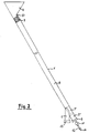
- FIG. 1 and 2 show partially schematic embodiments of conveyor devices according to the invention in cross section.
- an obliquely downwardly extending tube 1 is closed at both ends 2, 3. Near the upper end 2, a filler neck 4 opens from the top of the tube 1.
- a plug 7 which largely fills the internal cross section, is movably arranged via a thread 8 between a stop 10 just below the filler neck 4 and the lower end 3 of the tube.
- the reference symbols 7 'and 7 "indicate two further layers of the plug.
- the thread 8 can be moved by a schematically indicated winch 9.
- the tube 1 of the embodiment shown in FIG. 2 ends at the top in a filler neck 4. Shortly before the lower end 3 of the tube 1, an outlet neck 5 is provided, which can be closed by a shut-off element 13. At the lower end 3, a compressed air line 14 with a shut-off valve 12 and a pressure reducer 11 is connected to the pipe 1.
- the plug 7, which largely fills the inner cross section of the tube 1, can be moved between a stop 10 below the filler neck 4 and the lower end 3 of the tube by means of compressed air which can be introduced through the compressed air line.
- plug 7 is located at or near the upper stop 10. As material is supplied, plug 7 is lowered in the direction of the lower end 3 of the pipe 1 by controlling the compressed air flow accordingly.
- the shut-off device 13 is opened.
- the plug 7 is lowered into the lower end position 7 ", the transported material leaves the pipe 1 via the outlet connection 5.
- the plug 7 is moved again until the stop 10 at the upper pipe end.
Landscapes
- Engineering & Computer Science (AREA)
- Mechanical Engineering (AREA)
- Chutes (AREA)
- Basic Packing Technique (AREA)
- Filling Or Emptying Of Bunkers, Hoppers, And Tanks (AREA)
Applications Claiming Priority (2)
| Application Number | Priority Date | Filing Date | Title |
|---|---|---|---|
| DE19505255 | 1995-02-16 | ||
| DE1995105255 DE19505255C2 (de) | 1995-02-16 | 1995-02-16 | Vorrichtung zur Förderung kleinstückiger Güter |
Publications (2)
| Publication Number | Publication Date |
|---|---|
| EP0727366A2 true EP0727366A2 (fr) | 1996-08-21 |
| EP0727366A3 EP0727366A3 (fr) | 1998-03-18 |
Family
ID=7754163
Family Applications (1)
| Application Number | Title | Priority Date | Filing Date |
|---|---|---|---|
| EP96102157A Ceased EP0727366A3 (fr) | 1995-02-16 | 1996-02-14 | Dispositif pour transporter des petites pièces |
Country Status (2)
| Country | Link |
|---|---|
| EP (1) | EP0727366A3 (fr) |
| DE (1) | DE19505255C2 (fr) |
Cited By (2)
| Publication number | Priority date | Publication date | Assignee | Title |
|---|---|---|---|---|
| WO2003074395A1 (fr) * | 2002-03-06 | 2003-09-12 | Matcon (R & D) Limited | Dispositif de transfert de matiere fluide |
| WO2007011283A1 (fr) * | 2005-07-15 | 2007-01-25 | Astrazeneca Ab | Procede et dispositif de transport d'un materiau particulaire |
Families Citing this family (1)
| Publication number | Priority date | Publication date | Assignee | Title |
|---|---|---|---|---|
| DE10323056B4 (de) * | 2003-05-20 | 2006-07-06 | Rainer Klumpp | Fördersystem |
Family Cites Families (3)
| Publication number | Priority date | Publication date | Assignee | Title |
|---|---|---|---|---|
| DE7404393U (de) * | 1974-05-16 | Siemens Ag | Rohrpostbüchse | |
| US4573830A (en) * | 1984-06-21 | 1986-03-04 | International Business Machines Corporation | Chip decelerator |
| DE4041706C1 (en) * | 1990-12-24 | 1991-12-12 | L. B. Bohle Pharmatechnik Gmbh, 4722 Ennigerloh, De | Charging storage or transport containers with tablets - from elevated position via telescopic feed pipe |
-
1995
- 1995-02-16 DE DE1995105255 patent/DE19505255C2/de not_active Expired - Fee Related
-
1996
- 1996-02-14 EP EP96102157A patent/EP0727366A3/fr not_active Ceased
Cited By (3)
| Publication number | Priority date | Publication date | Assignee | Title |
|---|---|---|---|---|
| WO2003074395A1 (fr) * | 2002-03-06 | 2003-09-12 | Matcon (R & D) Limited | Dispositif de transfert de matiere fluide |
| US7077261B2 (en) | 2002-03-06 | 2006-07-18 | Matcon (R&D) Limited | Apparatus for transferring flowable material |
| WO2007011283A1 (fr) * | 2005-07-15 | 2007-01-25 | Astrazeneca Ab | Procede et dispositif de transport d'un materiau particulaire |
Also Published As
| Publication number | Publication date |
|---|---|
| DE19505255C2 (de) | 1996-12-05 |
| DE19505255A1 (de) | 1996-08-22 |
| EP0727366A3 (fr) | 1998-03-18 |
Similar Documents
| Publication | Publication Date | Title |
|---|---|---|
| DE3727561A1 (de) | Vorrichtung zum beladen eines silofahrzeuges oder dergleichen mit rieselfaehigem schuettgut | |
| EP0658502B1 (fr) | Dispositif de chargement d'un véhicule-silo | |
| EP0727366A2 (fr) | Dispositif pour transporter des petites pièces | |
| EP3453648A1 (fr) | Dispositif d'alimentation | |
| DE3708653C2 (de) | Verladevorrichtung für lose Verladung von staubigen Schüttgütern | |
| DE3613394A1 (de) | Verfahren und vorrichtung zum fuellen von grosssaecken | |
| EP0473941A1 (fr) | Procédé pour transporter des matériaux en poudre ou en grain sensibles à l'oxygène et dispositif pour la réalisation du procédé | |
| DE2701343A1 (de) | Einrichtung zum beladen von eisenbahnwaggons, lastwagen und behaeltern im allgemeinen mit losen materialien | |
| DE3524291C2 (de) | Kommissioniereinrichtung für Waren | |
| DE598438C (de) | Vorrichtung zum kontinuierlichen Foerdern von koernigen Massenguetern, insbesondere von Beton u. dgl., mittels Luft | |
| DE4330796A1 (de) | Vorrichtung zum Überführen eines breiten Fördergutstromes zu einem abzufördernden einspurigen Fördergutstrom | |
| DE68901692T2 (de) | Automatische vorrichtung zum entfernen von verschiedenen artikeln, insbesondere kapseln, tabletten und dragees aus in einem streifen ausgebildeten, angepassten hoheraeumen. | |
| DE2219914C3 (de) | Fütterungs- und Dosieranlage | |
| DE3810191A1 (de) | Druckluftentleereinrichtung fuer einen schuettgutbehaelter mit mindestens zwei entleeroeffnungen sowie ein verfahren zur entleerung des schuettgutbehaelters | |
| DE1102650B (de) | Pneumatischer Foerderer zum Foerdern von Massenguetern mittels Druckluft aus einem Behaelter in eine Rohrleitung | |
| DE3011954C2 (de) | Aufhängung für Obenentnahme-Einrichtungen | |
| DE1506965A1 (de) | Verfahren und Vorrichtung zum pneumatischen Foerdern und Dosieren von koernigen und pulverfoermigen Stoffen,insbesondere Granulaten | |
| DE3012047C2 (de) | Dosiereinrichtung zum Fördern von flüssigem Metall | |
| DE19541674A1 (de) | Vorrichtung zur Zuführung von Tabletten zu pharmazeutischen Zwecken oder eines anderen gleichartigen losen Produktes zwischen auf unterschiedlichen Ebenen angeordneten Arbeitseinheiten | |
| DE3408271A1 (de) | Vorrichtung zum pneumatischen, lotrechten foerdern von foerdergut, wie getreide | |
| EP1429982B1 (fr) | Dispositif de transport pneumatique | |
| DE6607956U (de) | Vorrichtung zum pneumatischen foerdern und dosieren von koernigen und pulverfoermigen stoffen, insbesondere granulaten. | |
| DE102004004207B4 (de) | Futterdosiereinrichtung | |
| EP1437282A1 (fr) | Dispositif et procédé pour le remplissage d'une sablière de frein d' un véhicule | |
| DE2403942B2 (de) | Vorrichtung zur zufuehrung von dosierten mengen verschiedener loser feststoffe zu den duesen eines bodenblasenden konverters |
Legal Events
| Date | Code | Title | Description |
|---|---|---|---|
| PUAI | Public reference made under article 153(3) epc to a published international application that has entered the european phase |
Free format text: ORIGINAL CODE: 0009012 |
|
| 17P | Request for examination filed |
Effective date: 19960220 |
|
| AK | Designated contracting states |
Kind code of ref document: A2 Designated state(s): DE ES FR GB IT |
|
| PUAL | Search report despatched |
Free format text: ORIGINAL CODE: 0009013 |
|
| AK | Designated contracting states |
Kind code of ref document: A3 Designated state(s): DE ES FR GB IT |
|
| GRAG | Despatch of communication of intention to grant |
Free format text: ORIGINAL CODE: EPIDOS AGRA |
|
| 17Q | First examination report despatched |
Effective date: 19990201 |
|
| STAA | Information on the status of an ep patent application or granted ep patent |
Free format text: STATUS: THE APPLICATION HAS BEEN REFUSED |
|
| 18R | Application refused |
Effective date: 19990920 |