EP0727520A2 - Distributeur de produit de lavage pour machine à laver domestique - Google Patents
Distributeur de produit de lavage pour machine à laver domestique Download PDFInfo
- Publication number
- EP0727520A2 EP0727520A2 EP96101927A EP96101927A EP0727520A2 EP 0727520 A2 EP0727520 A2 EP 0727520A2 EP 96101927 A EP96101927 A EP 96101927A EP 96101927 A EP96101927 A EP 96101927A EP 0727520 A2 EP0727520 A2 EP 0727520A2
- Authority
- EP
- European Patent Office
- Prior art keywords
- guide
- slide
- chamber
- wall
- bulkhead
- Prior art date
- Legal status (The legal status is an assumption and is not a legal conclusion. Google has not performed a legal analysis and makes no representation as to the accuracy of the status listed.)
- Granted
Links
Images

Classifications
-
- D—TEXTILES; PAPER
- D06—TREATMENT OF TEXTILES OR THE LIKE; LAUNDERING; FLEXIBLE MATERIALS NOT OTHERWISE PROVIDED FOR
- D06F—LAUNDERING, DRYING, IRONING, PRESSING OR FOLDING TEXTILE ARTICLES
- D06F39/00—Details of washing machines not specific to a single type of machines covered by groups D06F9/00 - D06F27/00
- D06F39/02—Devices for adding soap or other washing agents
Definitions
- the invention relates to a detergent dispenser for a household washing machine with a chamber which can be adapted by means of moving parts for the use of washing powder or liquid detergent.
- Such a detergent dispenser is known from DE 36 08 619 C2.
- a bulk boundary wall is guided as a movable part in at least two substantially vertically oriented sliding guides on the two side walls of the chamber, so that it can be pushed to the bottom of the chamber.
- this bulkhead In a raised position this bulkhead is adapted to the use of washing powder and in a lowered position to the use of liquid washing aids.
- this bulk boundary wall In order to adapt the detergent chamber equipped with it to smaller portions of washing powder or liquid washing aids, this bulk boundary wall must be repositioned from one sliding guide into another sliding guide. It is first completely removed from the detergent drawer. If the operator is called up during this process, the bulkhead wall that has been removed from the detergent drawer can be lost.
- the handling of such a bulkhead wall is cumbersome when inserted into the slide guides; the respective slide guide can be missed when it is inserted, so that the bulkhead wall occupies an unsafe position and - if this was not recognized - can be rinsed out of the detergent drawer to the rear during the next rinsing process.
- the bulkhead wall can be flushed into the washing machine's tub with the detergent. If this bulkhead wall gets caught inside the tub, e.g. the radiator can even damage the radiator, its fasteners or the temperature sensor.
- the invention has for its object to provide a detergent dispenser of the type mentioned above with a movable bulkhead wall which can neither be lost nor get into the washing machine's tub as a loose part and which is easier to handle without the risk of unsafe positioning.
- the movable part is a bulkhead wall held on a thrust guide oriented essentially transversely to its main extent, which wall is adapted to adapt to the use of washing powder a rear raised position of the drawer guide and for adaptation to the use of liquid detergents is adjustable in a front lowered position.
- the new thrust guide of the bulkhead wall Due to the new thrust guide of the bulkhead wall, if desired, it can be positioned in any number of positions of the drawer guide and even serve as a bulkhead wall for the use of liquid detergents in at least one front lowered position.
- the pouring restriction wall according to the invention no longer has to be removed from the chamber for the purpose of adaptation, but is only moved in a slide guide within the chamber and, if necessary, lowered or raised again from the lowered position. The disadvantages associated with the removal of the known bulkhead wall are therefore avoided.
- the bulk boundary wall has at least one additional latching position on the guide path between the rear raised position and the front lowered position for adapting the chamber volume to different required amounts of washing powder in the raised position.
- the bulk boundary wall is attached to a slide with lateral guide elements which are slidably guided in the opposite guide elements on the distance between the rear and the front position and are rotationally guided in the front position for lowering the bulk barrier wall.
- the bulkhead wall according to the invention can also be removed from the chamber so that both parts can be cleaned independently of one another. To do this, the detergent dispenser tray must be removed from its housing.
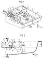
- the detergent drawer shown in Fig. 1 has three chambers open at the top, 1, 2 and 3. On its side, the drawer carries guide rails 4 and 5, by means of which the drawer is moved in guide grooves of a housing, not shown, in the pushing and pulling direction 6 can.
- the front bar 7 is used to mount a handle plate, not shown.
- the chamber 3 of the detergent drawer is equipped according to the prior art with a fixed bulkhead 8. It can only be used for powder detergents - here for prewash detergents.
- the chamber 2 is provided for liquid washing aids, preferably for fabric softeners.
- a known siphon system 9 is installed in the chamber, which has a non-visible stowage wall at the rear, which is not shown in detail here.
- the front chamber 1 is used to fill and store a dose of a main detergent, which can be in powder or liquid form.
- a main detergent which can be in powder or liquid form.
- the side chamber walls are stabilized by a bridge 11. Below that are attached to the chamber walls extending to the front guide rails 12. Together with other, but not visible in Fig. 1 slide guide strips, these strips 12 hold a frame-shaped slide 13 which carries the bulkhead wall 14 at its front end.
- the bulkhead wall 14 has a handle 15 on its front surface.
- the bulkhead wall is shown in Fig. 1 in the rear raised position of the drawer slide and is set in this position for use with a large portion of washing powder.
- This is indicated by the side wall marking, which contains an arrow 16 and a stylized representation 17 for a large portion of washing powder.
- the markings 18 are provided for the front raised position of the drawer guide for using the chamber with a small detergent dose and 19 for the front lowered position for using the chamber for a liquid detergent dose.
- the slide 20 is shown in its three positions provided in this exemplary embodiment.
- the rear raised position for adaptation to washing powder use with large doses is shown by the single-dot dashed representation.
- the lateral guide element 201 is - as will be explained further below - a pot which is open to the side and whose circular shape forms a swivel joint for the lowering in the front position.
- the frame 20 of the slide 13 is supported on the one hand on the lower slide guide bar 21; because of its overweight to the front, the frame is held upwards at the rear end by the pot 201 on the upper slide guide bar 12.
- the bulkhead wall 14 can thereby be transferred from the front raised position according to arrow 22 into the front lowered, triple-dashed position and can be held in this new position in that lateral locking grooves on the frame 20 of the slide 13 align with the lower thrust guide -Lock bar 21.
- the side strips 202 on the chamber wall between the guide strips 12 and 21 serve to lock the pot 201, which pulls on the slide 13 to the front bumps against the end faces of the strips 202. These end faces lie on a cylindrical surface which corresponds to the outer surface of the pot 201. As will be explained further below, the pot 201 can be lifted over the strips 202 so that the slide 13 can be completely removed from the chamber. This makes it easy to clean both the slide and the chamber.
- FIG. 3 clearly shows that the upper guide bar 12 and the lower guide bar 21 guide the frame in the vertical direction.
- the frame 20 is guided through the strips 202 in the horizontal direction.
- the strips 202 on the right in FIG. 3 are continued on the rear part of the chamber, so that the pouring boundary wall 14 in the lowered position is not obstructed by the sloping side of the chamber wall on the right.
- the slide 13 is shown enlarged compared to the previous representations in FIGS. 4 and 5. Its frame 20 is stabilized by means of rib-shaped reinforcements 203 on the side of the bulkhead delimitation wall 14 and carries one of the pots 201 on the outside at the rear ends of the side rails 204.
- such a pot 201 is hollow on the inside and has two parallel ribs 205 which retract obliquely backwards.
- the pot strikes with its cylinder part 206 against the end faces of the strips 202 (FIG. 2) when the slide 13 is pulled and prevents the slide from falling out of the slide guide 12, 21, but when the slide 13 is reinserted, these oblique ribs 205 slide from the inside onto the strips 202 and briefly force the ends of the frame bars 204 together until the pots 201 have been pushed past the strips and fall back into their original guide position between the guide strips 12 and 21.
- the latching bar 206 which is attached to the outside of the spars 204, slides along the entire guide path with its latching lugs 207 under the upper guide bar 12.
- the latching lugs 207 stop the movement of the slide 13 by abutment on the rear lower edge of a further bridge 211 between the chamber walls, which is part of the guide strips 12, so that this respective position is defined in a tangible manner.
- the slide 13 can be pushed into the front lowered position.
- a force must be overcome, which is given by the chamfered section 208 of the lower edge of each spar on the lower guide bar 21.
- the spars 204 in this section 208 must withdraw from the lower guide strips 21 until they fall into the locking grooves 209 which are provided obliquely in the spars 204.
- the frame 20 is rotatably guided on the end faces of the strips 202 by means of the pots 201. In the lower, lowered position, the frame is finally held in the locking grooves 209 by the guide strips 21.
- the latching groove also has a chamfer on its lower edge, via which the guide bar 21 can be lifted out of the latching groove again and guided under this spar via the outside of the spar 204.
- the frame 20 of the slide 13 has finger loops 210 on the inner sides of the ends of the frame bars 204, which are pressed together with the thumb and forefinger in the forward, raised position of the slide 13 can.
- the spars 204 bend elastically inwards and pull the pots 201 out of their guiding position between the guide strips 12 and 21. Then the slide 13 can be pulled off to the front, the pots 201 being raised above the stop on the end faces of the strips 202 and slide over these ledges.
Landscapes
- Engineering & Computer Science (AREA)
- Textile Engineering (AREA)
- Detail Structures Of Washing Machines And Dryers (AREA)
Applications Claiming Priority (2)
| Application Number | Priority Date | Filing Date | Title |
|---|---|---|---|
| DE19505734 | 1995-02-20 | ||
| DE19505734A DE19505734A1 (de) | 1995-02-20 | 1995-02-20 | Waschmittel-Einspüleinrichtung für eine Haushaltwaschmaschine |
Publications (3)
| Publication Number | Publication Date |
|---|---|
| EP0727520A2 true EP0727520A2 (fr) | 1996-08-21 |
| EP0727520A3 EP0727520A3 (fr) | 1996-12-27 |
| EP0727520B1 EP0727520B1 (fr) | 1999-09-08 |
Family
ID=7754477
Family Applications (1)
| Application Number | Title | Priority Date | Filing Date |
|---|---|---|---|
| EP96101927A Expired - Lifetime EP0727520B1 (fr) | 1995-02-20 | 1996-02-09 | Distributeur de produit de lavage pour machine à laver domestique |
Country Status (3)
| Country | Link |
|---|---|
| EP (1) | EP0727520B1 (fr) |
| DE (2) | DE19505734A1 (fr) |
| ES (1) | ES2138251T3 (fr) |
Cited By (6)
| Publication number | Priority date | Publication date | Assignee | Title |
|---|---|---|---|---|
| WO2005116322A1 (fr) * | 2004-04-14 | 2005-12-08 | Lg Electronics Inc. | Bac a detergent pour machine a laver |
| EP1764437A1 (fr) * | 2005-09-16 | 2007-03-21 | Whirlpool Corporation | Distributeur de détergent pour une machine à laver le linge |
| EP1607508A3 (fr) * | 2004-06-14 | 2007-06-27 | Samsung Electronics Co., Ltd. | Machine à laver avec distributeur de détergent correspondant |
| CN102575410A (zh) * | 2009-08-12 | 2012-07-11 | 伊莱克斯家用产品股份有限公司 | 具有清洁剂隔室的家用设备 |
| EP2889419A1 (fr) * | 2013-12-24 | 2015-07-01 | Electrolux Appliances Aktiebolag | Machine à laver le linge |
| CN106460295A (zh) * | 2014-06-23 | 2017-02-22 | Lg电子株式会社 | 洗衣机的洗涤剂供给装置 |
Families Citing this family (5)
| Publication number | Priority date | Publication date | Assignee | Title |
|---|---|---|---|---|
| KR101013374B1 (ko) * | 2003-11-10 | 2011-02-14 | 삼성전자주식회사 | 세제공급장치를 갖춘 세탁기 |
| EP2003237B1 (fr) | 2007-06-12 | 2016-05-04 | Electrolux Home Products Corporation N.V. | Distributeur de produits détergents pour un lave-linge |
| SI2460925T1 (sl) | 2010-12-01 | 2014-05-30 | Primus Ce, S.R.O. | Razdeljevalnik detergenta pri pralnem stroju |
| CN102444005B (zh) * | 2011-09-23 | 2013-09-04 | 南京乐金熊猫电器有限公司 | 防止液体类洗涤剂误投入的装置及方法 |
| DE102023206848A1 (de) * | 2023-07-19 | 2025-01-23 | BSH Hausgeräte GmbH | Einspülschale für ein Wäschebehandlungsgerät |
Family Cites Families (2)
| Publication number | Priority date | Publication date | Assignee | Title |
|---|---|---|---|---|
| DE3608619A1 (de) * | 1986-03-14 | 1987-09-17 | Bosch Siemens Hausgeraete | Waschmaschine mit einer waschmittel-einspuelschale |
| DE4325821A1 (de) * | 1993-07-31 | 1995-02-02 | Foron Waschgeraete Gmbh | Einrichtung zum Einspülen von Wasch- und/oder Pflegemitteln in Wasch- oder Geschirrspülmaschinen |
-
1995
- 1995-02-20 DE DE19505734A patent/DE19505734A1/de not_active Withdrawn
-
1996
- 1996-02-09 EP EP96101927A patent/EP0727520B1/fr not_active Expired - Lifetime
- 1996-02-09 DE DE59602978T patent/DE59602978D1/de not_active Expired - Fee Related
- 1996-02-09 ES ES96101927T patent/ES2138251T3/es not_active Expired - Lifetime
Cited By (12)
| Publication number | Priority date | Publication date | Assignee | Title |
|---|---|---|---|---|
| WO2005116322A1 (fr) * | 2004-04-14 | 2005-12-08 | Lg Electronics Inc. | Bac a detergent pour machine a laver |
| US7428831B2 (en) | 2004-04-14 | 2008-09-30 | Lg Electronics Inc. | Detergent container of washing machine |
| EP1607508A3 (fr) * | 2004-06-14 | 2007-06-27 | Samsung Electronics Co., Ltd. | Machine à laver avec distributeur de détergent correspondant |
| EP1764437A1 (fr) * | 2005-09-16 | 2007-03-21 | Whirlpool Corporation | Distributeur de détergent pour une machine à laver le linge |
| CN102575410A (zh) * | 2009-08-12 | 2012-07-11 | 伊莱克斯家用产品股份有限公司 | 具有清洁剂隔室的家用设备 |
| CN102575410B (zh) * | 2009-08-12 | 2015-06-17 | 伊莱克斯家用产品股份有限公司 | 具有清洁剂隔室的家用设备 |
| EP2889419A1 (fr) * | 2013-12-24 | 2015-07-01 | Electrolux Appliances Aktiebolag | Machine à laver le linge |
| WO2015096988A1 (fr) * | 2013-12-24 | 2015-07-02 | Electrolux Appliances Aktiebolag | Machine à laver le linge |
| CN106460295A (zh) * | 2014-06-23 | 2017-02-22 | Lg电子株式会社 | 洗衣机的洗涤剂供给装置 |
| EP3158123A4 (fr) * | 2014-06-23 | 2017-11-22 | LG Electronics Inc. | Dispositif d'alimentation en détergent pour machine à laver |
| CN106460295B (zh) * | 2014-06-23 | 2019-01-22 | Lg电子株式会社 | 洗衣机的洗涤剂供给装置 |
| US10508381B2 (en) | 2014-06-23 | 2019-12-17 | Lg Electronics Inc. | Detergent feeding device for washer |
Also Published As
| Publication number | Publication date |
|---|---|
| ES2138251T3 (es) | 2000-01-01 |
| EP0727520A3 (fr) | 1996-12-27 |
| EP0727520B1 (fr) | 1999-09-08 |
| DE59602978D1 (de) | 1999-10-14 |
| DE19505734A1 (de) | 1996-08-22 |
Similar Documents
| Publication | Publication Date | Title |
|---|---|---|
| EP0727520B1 (fr) | Distributeur de produit de lavage pour machine à laver domestique | |
| DE1810636A1 (de) | Automatische Geschirrspuelmaschine | |
| DE1237744B (de) | Geschirrtrageinrichtung fuer eine Geschirrspuelmaschine | |
| DE924232C (de) | Kleiderablage od. dgl. mit rohrfoermigem laengs geschlitztem Tragrohr zur Aufnahme von Traghaken | |
| DE2231517A1 (de) | Stanzvorrichtung zum lochen der wand von rohren | |
| DE3045103A1 (de) | Ablegeschrank | |
| DE60302213T2 (de) | Geschirrkorb für Geschirrspülmaschinen | |
| DE2044365A1 (de) | Schrank, insbesondere Büroschrank für Hängeregistratur | |
| DE3607632C2 (fr) | ||
| DE3414474A1 (de) | Kaesepresse | |
| DE3230751C2 (fr) | ||
| EP3598924B1 (fr) | Support, insert et dispositif de distribution pour des marchandises non emballées | |
| DE2941578C2 (de) | Dosiervorrichtung für Flüssigkeiten | |
| DE10117546A1 (de) | Zusammenlegbarer Trockenständer | |
| DE187435C (fr) | ||
| DE3825277C2 (fr) | ||
| DE2209532A1 (de) | Stange zum einfuehren von vorhangtraegern | |
| DE2328604C3 (de) | Liefergestell für das portionsweise Entleeren von Brühpulverpackungen | |
| EP0385190A1 (fr) | Appareil pour la distribution automatique en quantité définie d'un liquide actif, sous contrôle de la chasse d'eau, dans le réservoir de la toilette | |
| EP0213280A2 (fr) | Séchoir à linge extensible | |
| AT275202B (de) | Füllvorrichtung zum Auffüllen vertikaler Speicherkanäle einer Garnspulen-Verkaufseinrichtung | |
| DE2508036B2 (de) | Verriegelungsvorrichtung für in einem Gehäuse oder Gestell übereinander angeordnete Schubladen | |
| DE3342082A1 (de) | Abdeckhaltevorrichtung fuer oben offene transportbehaelter | |
| DE64256C (de) | Vorrichtung zum Schlitzen | |
| DE7601025U1 (de) | Dosiervorrichtung für eine Flüssigkeit |
Legal Events
| Date | Code | Title | Description |
|---|---|---|---|
| PUAI | Public reference made under article 153(3) epc to a published international application that has entered the european phase |
Free format text: ORIGINAL CODE: 0009012 |
|
| AK | Designated contracting states |
Kind code of ref document: A2 Designated state(s): DE ES FR GB IT |
|
| PUAL | Search report despatched |
Free format text: ORIGINAL CODE: 0009013 |
|
| AK | Designated contracting states |
Kind code of ref document: A3 Designated state(s): DE ES FR GB IT |
|
| 17P | Request for examination filed |
Effective date: 19970617 |
|
| RAP1 | Party data changed (applicant data changed or rights of an application transferred) |
Owner name: BSH BOSCH UND SIEMENS HAUSGERAETE GMBH |
|
| GRAG | Despatch of communication of intention to grant |
Free format text: ORIGINAL CODE: EPIDOS AGRA |
|
| GRAG | Despatch of communication of intention to grant |
Free format text: ORIGINAL CODE: EPIDOS AGRA |
|
| GRAH | Despatch of communication of intention to grant a patent |
Free format text: ORIGINAL CODE: EPIDOS IGRA |
|
| 17Q | First examination report despatched |
Effective date: 19990226 |
|
| GRAH | Despatch of communication of intention to grant a patent |
Free format text: ORIGINAL CODE: EPIDOS IGRA |
|
| GRAA | (expected) grant |
Free format text: ORIGINAL CODE: 0009210 |
|
| AK | Designated contracting states |
Kind code of ref document: B1 Designated state(s): DE ES FR GB IT |
|
| ET | Fr: translation filed | ||
| GBT | Gb: translation of ep patent filed (gb section 77(6)(a)/1977) |
Effective date: 19990910 |
|
| REF | Corresponds to: |
Ref document number: 59602978 Country of ref document: DE Date of ref document: 19991014 |
|
| ITF | It: translation for a ep patent filed | ||
| REG | Reference to a national code |
Ref country code: ES Ref legal event code: FG2A Ref document number: 2138251 Country of ref document: ES Kind code of ref document: T3 |
|
| PLBE | No opposition filed within time limit |
Free format text: ORIGINAL CODE: 0009261 |
|
| STAA | Information on the status of an ep patent application or granted ep patent |
Free format text: STATUS: NO OPPOSITION FILED WITHIN TIME LIMIT |
|
| 26N | No opposition filed | ||
| REG | Reference to a national code |
Ref country code: GB Ref legal event code: IF02 |
|
| PGFP | Annual fee paid to national office [announced via postgrant information from national office to epo] |
Ref country code: GB Payment date: 20030127 Year of fee payment: 8 |
|
| PGFP | Annual fee paid to national office [announced via postgrant information from national office to epo] |
Ref country code: ES Payment date: 20030206 Year of fee payment: 8 |
|
| PGFP | Annual fee paid to national office [announced via postgrant information from national office to epo] |
Ref country code: FR Payment date: 20030221 Year of fee payment: 8 |
|
| PG25 | Lapsed in a contracting state [announced via postgrant information from national office to epo] |
Ref country code: GB Free format text: LAPSE BECAUSE OF NON-PAYMENT OF DUE FEES Effective date: 20040209 |
|
| PG25 | Lapsed in a contracting state [announced via postgrant information from national office to epo] |
Ref country code: ES Free format text: LAPSE BECAUSE OF NON-PAYMENT OF DUE FEES Effective date: 20040210 |
|
| GBPC | Gb: european patent ceased through non-payment of renewal fee |
Effective date: 20040209 |
|
| PG25 | Lapsed in a contracting state [announced via postgrant information from national office to epo] |
Ref country code: FR Free format text: LAPSE BECAUSE OF NON-PAYMENT OF DUE FEES Effective date: 20041029 |
|
| REG | Reference to a national code |
Ref country code: FR Ref legal event code: ST |
|
| PG25 | Lapsed in a contracting state [announced via postgrant information from national office to epo] |
Ref country code: IT Free format text: LAPSE BECAUSE OF NON-PAYMENT OF DUE FEES;WARNING: LAPSES OF ITALIAN PATENTS WITH EFFECTIVE DATE BEFORE 2007 MAY HAVE OCCURRED AT ANY TIME BEFORE 2007. THE CORRECT EFFECTIVE DATE MAY BE DIFFERENT FROM THE ONE RECORDED. Effective date: 20050209 |
|
| REG | Reference to a national code |
Ref country code: ES Ref legal event code: FD2A Effective date: 20040210 |
|
| PGFP | Annual fee paid to national office [announced via postgrant information from national office to epo] |
Ref country code: DE Payment date: 20090228 Year of fee payment: 14 |
|
| PG25 | Lapsed in a contracting state [announced via postgrant information from national office to epo] |
Ref country code: DE Free format text: LAPSE BECAUSE OF NON-PAYMENT OF DUE FEES Effective date: 20100901 |