EP0727804A2 - Un disjoncteur - Google Patents
Un disjoncteur Download PDFInfo
- Publication number
- EP0727804A2 EP0727804A2 EP96301112A EP96301112A EP0727804A2 EP 0727804 A2 EP0727804 A2 EP 0727804A2 EP 96301112 A EP96301112 A EP 96301112A EP 96301112 A EP96301112 A EP 96301112A EP 0727804 A2 EP0727804 A2 EP 0727804A2
- Authority
- EP
- European Patent Office
- Prior art keywords
- core
- spring
- pole piece
- coil
- tube
- Prior art date
- Legal status (The legal status is an assumption and is not a legal conclusion. Google has not performed a legal analysis and makes no representation as to the accuracy of the status listed.)
- Granted
Links
- 238000013016 damping Methods 0.000 claims description 5
- 239000012530 fluid Substances 0.000 claims description 3
- 230000015572 biosynthetic process Effects 0.000 claims description 2
- 230000000694 effects Effects 0.000 description 5
- 230000003111 delayed effect Effects 0.000 description 2
- 230000004907 flux Effects 0.000 description 1
- 239000007788 liquid Substances 0.000 description 1
Images

Classifications
-
- H—ELECTRICITY
- H01—ELECTRIC ELEMENTS
- H01H—ELECTRIC SWITCHES; RELAYS; SELECTORS; EMERGENCY PROTECTIVE DEVICES
- H01H71/00—Details of the protective switches or relays covered by groups H01H73/00 - H01H83/00
- H01H71/10—Operating or release mechanisms
- H01H71/12—Automatic release mechanisms with or without manual release
- H01H71/24—Electromagnetic mechanisms
- H01H71/34—Electromagnetic mechanisms having two or more armatures controlled by a common winding
- H01H71/345—Electromagnetic mechanisms having two or more armatures controlled by a common winding having a delayed movable core and a movable armature
Definitions
- THIS INVENTION relates to a circuit breaker. More particularly, the invention relates to an electro-magnetic operating device for a circuit breaker and to a circuit breaker including such device. The invention is intended particularly, but not necessarily exclusively, for use in the protection of electrical motors.
- the electrical load of a motor is characterised by a starting current and a running current.
- the starting or run-up current averages about six times the full load current of the motor but the peak of the first half cycle, the so-called "inrush" current, can reach a value of almost twenty times the motor RMS rated current.
- an electro-magnetic operating device for a circuit breaker including
- the load current of the item of electrical equipment which, as indicated above will normally be an electric motor, is carried by the coil of the circuit breaker.
- the load current generates magnetic flux in the magnetic path defining means which imparts the electro-magnetic force to the displaceable element.
- the displaceable element may comprise a core or plunger.
- the core is slidably mounted in a tube or canister, one end of the tube being closed off by an end wall and an opposed end of the tube being closed off, in a hermetic manner, by the pole piece.
- the core may be displaceable in a damped manner within the tube between its first position and its second position.
- a damping fluid of a predetermined viscosity may be contained within the tube for damping sliding movement of the core.
- the urging means may comprise a coil spring, one end of the spring abutting the pole piece and an opposed end of the spring abutting against a predetermined formation of the core.
- the core may have a region of reduced cross-section to define a shoulder against which said other end of the spring abuts.
- a spring force and a spring rate of the spring may match the electro-magnetic force applied to the core when the coil carries 100% of load current to hold the core in equilibrium intermediate its first position and its second position.
- the force on the core as a function of its gap is calculated for various load currents and plotted on a linear scale.
- the gap is the spacing between the core and the pole piece.
- the spring characteristic of the spring is drawn as a line tangential to the core electro-magnetic force corresponding to an operating current of 110% of load current. It will be appreciated that, when the coil carries current, the core has a tendency to be pulled towards the pole piece, thereby reducing the gap between the core and the pole piece. This has the effect of reducing the delayed tripping time and the instantaneous tripping time.
- the invention extends to a circuit breaker which includes an electro-magnetic operating device as described above.
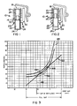
- an electro-magnetic operating device for a circuit breaker is illustrated and is designated generally by the reference numeral 10.
- the device 10 comprises a coil 12 defining a cavity 14 herein.
- a magnetic path defining means 16 is arranged at least partially around the coil 12.
- the magnetic path defining means 16 includes a pole piece 18 and a stator frame 20.
- a displaceable element in the form of a plunger or core 22 is mounted in a tube 24.
- the tube 24, in turn, is arranged within the cavity 14 defined by the coil 12. Further, the tube 24 protrudes through an opening 26 in the stator frame 20.
- One end of the tube 24 is closed off by an end wall 24.1 with an opposed end of the tube 24 being closed off, in a hermetic manner, by the pole piece 18.
- the core 22 is displaceable in a damped manner from the position shown in Figure 1 of the drawings to a position in which it abuts against the pole piece 18.
- the interior of the tube 24 contains a damping fluid in the form of a liquid of a predetermined viscosity.
- the device 10 includes an urging means in the form of a coil spring 28 for urging the core 22 to the position shown in Figure 1 of the drawings.
- One end of the coil spring 28 abuts against the pole piece 18 with an opposed end of the coil spring 28 abutting against a shoulder 30 defined in the core 22.
- the spring 28 is selected such that, when a load current of 100% is present in the coil 12, the electro-magnetic force imparted to the core 22 exceeds, by a predetermined amount, the spring force 28 imparted to the core 22 by the spring 28.
- the core 22 is displaced from its first position to a position intermediate its first position and its second position (where it is an abutment with the pole piece).
- the spring 28 is, accordingly, selected to have a balancing effect on the core 22 to hold it in equilibrium in the intermediate position shown in Figure 2 of the drawings and as represented at 40 in Figure 3 of the drawings.
- curve 42 shows the core electro-magnetic force characteristic when a load current of 100% is present in the coil 12.
- Curves 44 and 46 show the minimum trip current, being 105% of the load current, and the maximum trip current, being 115% of the load current, respectively.
- the curve 48 shows the core electro-magnetic force characteristic at 110% of load current being present in the coil 12.
- the curves 42 to 48 are plotted on a linear scale and the core spring characteristic is drawn as a line 50 tangential to the core electro-magnetic force corresponding to a nominal operating current of 110%, i.e. the line 50 is plotted tangential to the curve 48.
- the line 50 is plotted to have the maximum possible slope, which is representative of the maximum spring rate. Where the line 50 intersects the curve 42 (the 100% load current curve) the required spring rate or force is provided.
- curve 52 is representative of the time-delay and instantaneous tripping where the core 22 is in the position shown in Figure 1 of the drawings, i.e. at load currents less than 100%.
Landscapes
- Physics & Mathematics (AREA)
- Electromagnetism (AREA)
- Emergency Protection Circuit Devices (AREA)
- Electrophonic Musical Instruments (AREA)
- Breakers (AREA)
Applications Claiming Priority (2)
| Application Number | Priority Date | Filing Date | Title |
|---|---|---|---|
| ZA951389 | 1995-02-20 | ||
| ZA9501389 | 1995-02-20 |
Publications (3)
| Publication Number | Publication Date |
|---|---|
| EP0727804A2 true EP0727804A2 (fr) | 1996-08-21 |
| EP0727804A3 EP0727804A3 (fr) | 1997-12-29 |
| EP0727804B1 EP0727804B1 (fr) | 2001-05-02 |
Family
ID=25584844
Family Applications (1)
| Application Number | Title | Priority Date | Filing Date |
|---|---|---|---|
| EP96301112A Expired - Lifetime EP0727804B1 (fr) | 1995-02-20 | 1996-02-20 | Un disjoncteur |
Country Status (5)
| Country | Link |
|---|---|
| US (1) | US5677657A (fr) |
| EP (1) | EP0727804B1 (fr) |
| AT (1) | ATE200941T1 (fr) |
| DE (1) | DE69612633T2 (fr) |
| ZA (1) | ZA961068B (fr) |
Cited By (1)
| Publication number | Priority date | Publication date | Assignee | Title |
|---|---|---|---|---|
| EP1310971A3 (fr) * | 2001-10-18 | 2003-08-20 | Circuit Breaker Industries Limited | Mécanisme de disjoncteur réglable |
Families Citing this family (3)
| Publication number | Priority date | Publication date | Assignee | Title |
|---|---|---|---|---|
| US6794963B2 (en) * | 2002-04-24 | 2004-09-21 | General Electric Company | Magnetic device for a magnetic trip unit |
| JP2007234250A (ja) * | 2006-02-27 | 2007-09-13 | Fuji Electric Fa Components & Systems Co Ltd | 遮断機の引外し装置 |
| US8542084B1 (en) * | 2012-03-13 | 2013-09-24 | General Electric Company | Circuit protection device and trip unit for use with a circuit protection device |
Family Cites Families (4)
| Publication number | Priority date | Publication date | Assignee | Title |
|---|---|---|---|---|
| DE1019012B (de) * | 1956-09-10 | 1957-11-07 | Hermann Nier K G | Elektromagnetisches Rundrelais mit pneumatischer Hubverzoegerung |
| US2919325A (en) * | 1957-10-08 | 1959-12-29 | Murray Mfg Corp | Magnetic overload relay |
| US3689855A (en) * | 1970-04-27 | 1972-09-05 | Matsushita Electric Works Ltd | Circuit protector |
| US4504807A (en) * | 1984-06-01 | 1985-03-12 | Carlingswitch, Inc. | High inrush current circuit breaker |
-
1996
- 1996-02-09 ZA ZA961068A patent/ZA961068B/xx unknown
- 1996-02-13 US US08/600,680 patent/US5677657A/en not_active Expired - Fee Related
- 1996-02-20 AT AT96301112T patent/ATE200941T1/de not_active IP Right Cessation
- 1996-02-20 EP EP96301112A patent/EP0727804B1/fr not_active Expired - Lifetime
- 1996-02-20 DE DE69612633T patent/DE69612633T2/de not_active Expired - Fee Related
Cited By (1)
| Publication number | Priority date | Publication date | Assignee | Title |
|---|---|---|---|---|
| EP1310971A3 (fr) * | 2001-10-18 | 2003-08-20 | Circuit Breaker Industries Limited | Mécanisme de disjoncteur réglable |
Also Published As
| Publication number | Publication date |
|---|---|
| DE69612633D1 (de) | 2001-06-07 |
| EP0727804A3 (fr) | 1997-12-29 |
| ATE200941T1 (de) | 2001-05-15 |
| EP0727804B1 (fr) | 2001-05-02 |
| ZA961068B (en) | 1996-08-20 |
| US5677657A (en) | 1997-10-14 |
| DE69612633T2 (de) | 2001-08-09 |
Similar Documents
| Publication | Publication Date | Title |
|---|---|---|
| CA1299643C (fr) | Interrupteur de circuit numerique a parametres de declenchement pour moteur electrique | |
| US3959755A (en) | Circuit breaker with improved delay | |
| US5583732A (en) | Modular current transformer for electronic circuit interrupters | |
| CA2234699A1 (fr) | Dispositif de protection thermique avec blindage magnetique et disjoncteur incorporant celui-ci | |
| EP2088603A2 (fr) | Réacteur à dérivation | |
| Bellei et al. | Evaluating capacitor-switching devices for preventing nuisance tripping of adjustable-speed drives due to voltage magnification | |
| Stringer | The effect of DC offset on current-operated relays | |
| US5677657A (en) | Circuit breaker | |
| EP3921908B1 (fr) | Configuration de protection contre les défaillances pour un dispositif de protection de transformateur réarmable | |
| FI97428C (fi) | Kytkentäelin sähköistä kytkintä varten ja tällä kytkentäelimellä varustettu sähköinen kytkin | |
| CA2234506A1 (fr) | Ensemble de declencheur magnetique et disjoncteur incorporant celui-ci | |
| US6724597B1 (en) | Protection device for low voltage networks | |
| US5774320A (en) | Modular current transformer for electronic circuit interrupters | |
| US5343178A (en) | Electric circuit breaker | |
| US5684443A (en) | False-trip-resistant circuit breaker | |
| Cohen | Induction motors-protection and starting | |
| US2919325A (en) | Magnetic overload relay | |
| US2626377A (en) | Combination of an electric switch and air core reactor for protecting electrical equipment from excessive fault currents | |
| US5136454A (en) | Arrangement for providing ground fault protection | |
| Kilburn et al. | NEMA design E motors and controls-what's it all about? | |
| KR100516223B1 (ko) | 차단기의 원추 형상 코아를 가진 코일 장치 | |
| KR200333228Y1 (ko) | 배선용 차단기의 트립부 | |
| EP1895561B1 (fr) | Dispositif d'actionnement et appareil de commmutation électroméchanique | |
| Zinchenko et al. | Single-system differential cutoff of power transformers of rural power networks constructed from aperiodic magnetizing inrush current | |
| US4930038A (en) | Current overload tripping device with leading tripping action |
Legal Events
| Date | Code | Title | Description |
|---|---|---|---|
| PUAI | Public reference made under article 153(3) epc to a published international application that has entered the european phase |
Free format text: ORIGINAL CODE: 0009012 |
|
| AK | Designated contracting states |
Kind code of ref document: A2 Designated state(s): AT DE FR GB IT NL SE |
|
| PUAL | Search report despatched |
Free format text: ORIGINAL CODE: 0009013 |
|
| AK | Designated contracting states |
Kind code of ref document: A3 Designated state(s): AT DE FR GB IT NL SE |
|
| 17P | Request for examination filed |
Effective date: 19980318 |
|
| 17Q | First examination report despatched |
Effective date: 19990809 |
|
| GRAG | Despatch of communication of intention to grant |
Free format text: ORIGINAL CODE: EPIDOS AGRA |
|
| GRAG | Despatch of communication of intention to grant |
Free format text: ORIGINAL CODE: EPIDOS AGRA |
|
| GRAG | Despatch of communication of intention to grant |
Free format text: ORIGINAL CODE: EPIDOS AGRA |
|
| GRAH | Despatch of communication of intention to grant a patent |
Free format text: ORIGINAL CODE: EPIDOS IGRA |
|
| GRAH | Despatch of communication of intention to grant a patent |
Free format text: ORIGINAL CODE: EPIDOS IGRA |
|
| GRAA | (expected) grant |
Free format text: ORIGINAL CODE: 0009210 |
|
| AK | Designated contracting states |
Kind code of ref document: B1 Designated state(s): AT DE FR GB IT NL SE |
|
| PG25 | Lapsed in a contracting state [announced via postgrant information from national office to epo] |
Ref country code: NL Free format text: LAPSE BECAUSE OF FAILURE TO SUBMIT A TRANSLATION OF THE DESCRIPTION OR TO PAY THE FEE WITHIN THE PRESCRIBED TIME-LIMIT Effective date: 20010502 |
|
| REF | Corresponds to: |
Ref document number: 200941 Country of ref document: AT Date of ref document: 20010515 Kind code of ref document: T |
|
| REF | Corresponds to: |
Ref document number: 69612633 Country of ref document: DE Date of ref document: 20010607 |
|
| ET | Fr: translation filed | ||
| ITF | It: translation for a ep patent filed | ||
| PG25 | Lapsed in a contracting state [announced via postgrant information from national office to epo] |
Ref country code: SE Free format text: LAPSE BECAUSE OF FAILURE TO SUBMIT A TRANSLATION OF THE DESCRIPTION OR TO PAY THE FEE WITHIN THE PRESCRIBED TIME-LIMIT Effective date: 20010802 |
|
| NLV1 | Nl: lapsed or annulled due to failure to fulfill the requirements of art. 29p and 29m of the patents act | ||
| REG | Reference to a national code |
Ref country code: GB Ref legal event code: IF02 |
|
| PLBE | No opposition filed within time limit |
Free format text: ORIGINAL CODE: 0009261 |
|
| STAA | Information on the status of an ep patent application or granted ep patent |
Free format text: STATUS: NO OPPOSITION FILED WITHIN TIME LIMIT |
|
| 26N | No opposition filed | ||
| PGFP | Annual fee paid to national office [announced via postgrant information from national office to epo] |
Ref country code: AT Payment date: 20070213 Year of fee payment: 12 |
|
| PGFP | Annual fee paid to national office [announced via postgrant information from national office to epo] |
Ref country code: GB Payment date: 20070214 Year of fee payment: 12 |
|
| PGFP | Annual fee paid to national office [announced via postgrant information from national office to epo] |
Ref country code: DE Payment date: 20070215 Year of fee payment: 12 |
|
| PGFP | Annual fee paid to national office [announced via postgrant information from national office to epo] |
Ref country code: IT Payment date: 20070618 Year of fee payment: 12 |
|
| PGFP | Annual fee paid to national office [announced via postgrant information from national office to epo] |
Ref country code: FR Payment date: 20070208 Year of fee payment: 12 |
|
| GBPC | Gb: european patent ceased through non-payment of renewal fee |
Effective date: 20080220 |
|
| PG25 | Lapsed in a contracting state [announced via postgrant information from national office to epo] |
Ref country code: AT Free format text: LAPSE BECAUSE OF NON-PAYMENT OF DUE FEES Effective date: 20080220 |
|
| REG | Reference to a national code |
Ref country code: FR Ref legal event code: ST Effective date: 20081031 |
|
| PG25 | Lapsed in a contracting state [announced via postgrant information from national office to epo] |
Ref country code: DE Free format text: LAPSE BECAUSE OF NON-PAYMENT OF DUE FEES Effective date: 20080902 |
|
| PG25 | Lapsed in a contracting state [announced via postgrant information from national office to epo] |
Ref country code: FR Free format text: LAPSE BECAUSE OF NON-PAYMENT OF DUE FEES Effective date: 20080229 |
|
| PG25 | Lapsed in a contracting state [announced via postgrant information from national office to epo] |
Ref country code: GB Free format text: LAPSE BECAUSE OF NON-PAYMENT OF DUE FEES Effective date: 20080220 |
|
| PG25 | Lapsed in a contracting state [announced via postgrant information from national office to epo] |
Ref country code: IT Free format text: LAPSE BECAUSE OF NON-PAYMENT OF DUE FEES Effective date: 20080220 |