EP0727850A2 - Dispositif pour le positionnement d'un composant électrique ou électronique dans une boîte - Google Patents
Dispositif pour le positionnement d'un composant électrique ou électronique dans une boîte Download PDFInfo
- Publication number
- EP0727850A2 EP0727850A2 EP96101546A EP96101546A EP0727850A2 EP 0727850 A2 EP0727850 A2 EP 0727850A2 EP 96101546 A EP96101546 A EP 96101546A EP 96101546 A EP96101546 A EP 96101546A EP 0727850 A2 EP0727850 A2 EP 0727850A2
- Authority
- EP
- European Patent Office
- Prior art keywords
- sleeve
- housing
- component
- collar
- guide slots
- Prior art date
- Legal status (The legal status is an assumption and is not a legal conclusion. Google has not performed a legal analysis and makes no representation as to the accuracy of the status listed.)
- Granted
Links
Images
Classifications
-
- H—ELECTRICITY
- H01—ELECTRIC ELEMENTS
- H01R—ELECTRICALLY-CONDUCTIVE CONNECTIONS; STRUCTURAL ASSOCIATIONS OF A PLURALITY OF MUTUALLY-INSULATED ELECTRICAL CONNECTING ELEMENTS; COUPLING DEVICES; CURRENT COLLECTORS
- H01R13/00—Details of coupling devices of the kinds covered by groups H01R12/70 or H01R24/00 - H01R33/00
- H01R13/46—Bases; Cases
- H01R13/502—Bases; Cases composed of different pieces
- H01R13/508—Bases; Cases composed of different pieces assembled by a separate clip or spring
-
- H—ELECTRICITY
- H01—ELECTRIC ELEMENTS
- H01R—ELECTRICALLY-CONDUCTIVE CONNECTIONS; STRUCTURAL ASSOCIATIONS OF A PLURALITY OF MUTUALLY-INSULATED ELECTRICAL CONNECTING ELEMENTS; COUPLING DEVICES; CURRENT COLLECTORS
- H01R13/00—Details of coupling devices of the kinds covered by groups H01R12/70 or H01R24/00 - H01R33/00
- H01R13/73—Means for mounting coupling parts to apparatus or structures, e.g. to a wall
- H01R13/74—Means for mounting coupling parts in openings of a panel
- H01R13/741—Means for mounting coupling parts in openings of a panel using snap fastening means
- H01R13/743—Means for mounting coupling parts in openings of a panel using snap fastening means integral with the housing
Definitions
- the invention relates to a device for fixing an electrical or electronic component with a housing, for example a plug part, a coupling part, a sensor or the like in a through opening of a chassis wall or a machine element.
- DE-GM 94 10 147 is also to be mentioned here, which illustrates an electrical connection system, in particular for connecting a wear indicator sensor of a brake.
- a connector holder is provided, which can be fixed in a bore in a housing part, wherein it is held in this bore by an end-side contact shoulder on the one hand and by locking hooks on the other. No measures are provided here to secure the connector holder in place.
- This connector holder forms an interface in the connection system and serves to accommodate plug contact elements.
- the invention aims to provide a device that facilitates the assembly of such a component, its fixing in a through opening of a chassis wall or a machine element, especially in such a way that the assembly without the use of tools can be accomplished, and which is secured especially in its operationally intended location without additional design effort.
- the invention proposes those measures, the content and are the subject of the characterizing part of claim 1. Expedient embodiments of the invention are set out in the subclaims.
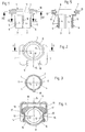
- the device has a sleeve 1 which is made in one piece from a resistant plastic material.
- This sleeve 1 has a cylindrical jacket 2. From the lower end face 3 of this sleeve 1, pairs of substantially axially parallel incisions 4 are provided at diametrically lying locations, through which 2 tabs 5 are cut free from this jacket, at the ends of which a radially projecting one , in cross section hook-shaped collar 6 is provided.
- the boundary surface of the collar 6 facing the end face 3 is chamfered like a wedge. It can be seen from FIGS.
- a radially projecting shoulder 7 is integrally formed on this sleeve 1, which merges into the sleeve 1 to form an inner shoulder 8 and an outer shoulder 9.
- the sleeve 1 has an outer and an inner circular cross section (Fig. 3).
- the receiving space delimited by the shoulder 7 and the inner shoulder is oval here (FIG. 2, FIG. 4).
- guide slots 10 are recessed in a position diametrically opposite one another.
- the legs 13 of this U-shaped wire spring 11 have mutually directed bends 14 (FIG. 4) which protrude through the openings 12 when the wire spring 11 is inserted and protrude into the oval receiving space delimited by the shoulder 7 and the inner shoulder 8.
- These bends 14 of the legs 13 of the wire spring 11 in the locked position are in relation to the direction of displacement (arrow 15) of the wire spring 11 on surfaces 16 and 17 which are inclined to this direction. It can also be seen from FIGS. 2 and 4 that when the wire spring 11 is in the locked position, the web 18 connecting the legs 13 thereof is distanced from the jacket of the sleeve 1 or from the shoulder 7 thereof.
- a longitudinal groove 19 is also formed on the sleeve 1 and forms a vertically extending positioning slot.
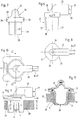
- the electrical or electronic component 20 to be received by this sleeve 1 is shown in FIGS. 6 to 8 in different views. It has a cylindrical housing 21 with a projecting, strip-like, longitudinal cam 22 and with cross-sectional dimensions which correspond in terms of their shape and size to the inner cross-section of the sleeve 1 (FIG. 3). At the top of this housing 21 is a collar 23 of oval shape, which is designed to correspond to the upper receiving space of the sleeve 1, which is delimited by the shoulder 7 and the inner shoulder 8 of this sleeve 1. At opposite points, 23 grooves 24 are formed on this collar. Cables 26 and 27 are introduced through an overhead grommet 25.
- This component 20 can be designed, for example, as a plug with an open end face 28. However, this component 20 can also be closed in a pot shape and have components in its interior that can be influenced, for example, capacitively, inductively or magnetically, if this component 20 is designed as a sensor.
- this component 20 is now to be fixed in a through opening 29 of a machine element 30 (FIGS. 9 to 11), the prepared through opening is inserted 29 inserted the sleeve 1, with its end face 3 ahead.
- the sleeve 1 is adapted to the machine element 30 insofar as the distance H of the shoulder 7 from the collar 6 of the tab 5 corresponds to the thickness S of the machine element 30.
- the tabs 5 When inserting the sleeve 1 into the through opening 29, the tabs 5 initially deflect radially inwards until the shoulder 7 abuts the machine element 30 and the collar 6 of the two tabs 5 lies outside the through opening 29, so that the tabs 5 are inherent Resilience resume their original position, the collars 6 of the tabs engage positively behind the edge of the through opening 29 (FIG. 11). For the time being, the sleeve 1 is fixed in the through opening 29.
- the wire spring 11 is retracted so that the bends 14 withdraw from the openings 12, this retraction of the wire spring 11 being facilitated by the fact that the web 18 is easy to grasp due to its distant position relative to the sleeve and due to the inclined surfaces 17 which when Withdrawing the wire spring 11, spread the legs 13 outwards.
- the component 20 is then inserted into the sleeve in the correct position, the strip-shaped cam 22 being received by the longitudinal groove 19. As a result, the component 20 is positioned radially.
- the component 20 is pushed into the sleeve 1 until the collar 23 lies in the receiving space delimited by the shoulder 7 and the inner shoulder 8.
- the grooves 24 are located on the collar 23 of the component 20 in a congruent position with the openings 12 in the guide slots 10, so that when the wire spring 11 is then pushed into its locking position, the bends 14 engage the grooves 24 in a positive manner.
- the component 20 is thus fixed in the sleeve 1 in the axial direction.
- the housing 21 of the component 20 bears directly on the back of the tabs 5, so that the tabs can no longer deflect radially inwards. In this way, the component 20 is securely fixed in the through opening 29 of the machine element 30 without the aid of a tool.
- the sleeve 1 for example, as angular.
- a plurality of incisions 4 can be provided in the jacket 2 of the sleeve 1, so that the jacket 2 of the sleeve consists of numerous tabs.
- pivoting locking elements can also be attached to the shoulder 7, or the locking element can be designed as a plug pin which can be inserted into a guide slot or into a guide bore.
- the housing 21 of the component 20 can be designed with respect to its cross sections such that the housing 21 only rests on the inside of the tabs in order to fix them in their position.
- the cross-sectional shape of the housing 21 can therefore deviate from the inner cross section of the sleeve 1.
- the housing 21 of the component 20 can also be longer than the sleeve 1, so that it protrudes from the end face 3 thereof.
- the length of the sleeve 1 and the length of the component 20 will generally be coordinated.
- the length of the tabs 5, however, results from the wall thickness of the chassis or the machine element on which the component is to be fixed.
- the wire spring 11 is retracted in the exemplary embodiment shown, so that its bends 14 pass out of the grooves 24 of the collar 23.
- the component 20 can then be pulled out of the sleeve. If the tabs 5 of the sleeve 1 are subsequently pressed against one another, the sleeve can also be pulled out of the through opening 29. No tools are required for these disassembly steps either.
Landscapes
- Details Of Connecting Devices For Male And Female Coupling (AREA)
- Connection Of Plates (AREA)
- Mounting Components In General For Electric Apparatus (AREA)
Applications Claiming Priority (2)
| Application Number | Priority Date | Filing Date | Title |
|---|---|---|---|
| DE19504821A DE19504821C2 (de) | 1995-02-14 | 1995-02-14 | Einrichtung zur Festlegung eines elektrischen oder elektronischen Bauteiles mit einem Gehäuse |
| DE19504821 | 1995-02-14 |
Publications (3)
| Publication Number | Publication Date |
|---|---|
| EP0727850A2 true EP0727850A2 (fr) | 1996-08-21 |
| EP0727850A3 EP0727850A3 (fr) | 1997-01-08 |
| EP0727850B1 EP0727850B1 (fr) | 1998-05-06 |
Family
ID=7753882
Family Applications (1)
| Application Number | Title | Priority Date | Filing Date |
|---|---|---|---|
| EP96101546A Expired - Lifetime EP0727850B1 (fr) | 1995-02-14 | 1996-02-03 | Dispositif pour le positionnement d'un composant électrique ou électronique dans une boíte |
Country Status (3)
| Country | Link |
|---|---|
| EP (1) | EP0727850B1 (fr) |
| DE (2) | DE19504821C2 (fr) |
| ES (1) | ES2117885T3 (fr) |
Cited By (3)
| Publication number | Priority date | Publication date | Assignee | Title |
|---|---|---|---|---|
| US6142799A (en) * | 1998-11-03 | 2000-11-07 | Hirschmann Austria Gmbh | Electrical plug connection |
| WO2007134564A1 (fr) | 2006-05-18 | 2007-11-29 | Epcos Ag | Capteur encliquetable |
| CN111919038A (zh) * | 2018-03-30 | 2020-11-10 | 米其林集团总公司 | 用于测量轮胎特性的盒子的附接系统 |
Families Citing this family (5)
| Publication number | Priority date | Publication date | Assignee | Title |
|---|---|---|---|---|
| JP3656689B2 (ja) * | 1996-08-30 | 2005-06-08 | 株式会社デンソー | センサ取付け用弾性部材、それを用いたセンサ取付け構造体およびそのセンサ取付け方法 |
| DE10201265B4 (de) * | 2002-01-15 | 2005-03-24 | Christian Bergner | Vorrichtung zum Halten von elektronischen Baugruppen und zum Übertragen von elektrischen Signalen bei elektronischen Baugruppen |
| DE10228689B4 (de) * | 2002-06-27 | 2016-03-17 | Conti Temic Microelectronic Gmbh | Verfahren zur Herstellung einer Baugruppe |
| DE102005003293A1 (de) * | 2005-01-24 | 2006-07-27 | Continental Teves Ag & Co. Ohg | Befestigungsvorrichtung für Sensoren oder Aktoren |
| DE102006008796B3 (de) * | 2006-02-24 | 2007-12-27 | Interactive Wear Ag | Fixiervorrichtung mit integrierter Elektronikkomponente |
Family Cites Families (6)
| Publication number | Priority date | Publication date | Assignee | Title |
|---|---|---|---|---|
| DE1823748U (de) * | 1960-03-24 | 1960-12-22 | Philips Nv | Vorrichtung zur befestigung eines einzelteiles, insbesondere eines elektrolytkondensators. |
| US3753582A (en) * | 1971-11-09 | 1973-08-21 | Anarak Inc | Coupling unit |
| GB2224891A (en) * | 1988-11-15 | 1990-05-16 | Itt Ind Ltd | Means for mounting an electrical or optical connector |
| US5025682A (en) * | 1990-06-18 | 1991-06-25 | Coltec Industries Inc. | Transmission solenoid retaining clip |
| DE4202849C1 (en) * | 1992-01-31 | 1993-06-03 | Dr.Ing.H.C. F. Porsche Ag, 7000 Stuttgart, De | Electrical plug and socket connector for automobile door panel - has pairs of locking and stop noses spaced by thickness of door panel allowing fitting at alternate depths in panel aperture |
| DE9410147U1 (de) * | 1994-06-23 | 1994-08-11 | Knott GmbH, 83125 Eggstätt | Elektrisches Anschlußsystem, insbesondere zum Anschluß eines Verschleißanzeigesensors einer Bremse |
-
1995
- 1995-02-14 DE DE19504821A patent/DE19504821C2/de not_active Expired - Fee Related
-
1996
- 1996-02-03 EP EP96101546A patent/EP0727850B1/fr not_active Expired - Lifetime
- 1996-02-03 ES ES96101546T patent/ES2117885T3/es not_active Expired - Lifetime
- 1996-02-03 DE DE59600179T patent/DE59600179D1/de not_active Expired - Lifetime
Cited By (7)
| Publication number | Priority date | Publication date | Assignee | Title |
|---|---|---|---|---|
| US6142799A (en) * | 1998-11-03 | 2000-11-07 | Hirschmann Austria Gmbh | Electrical plug connection |
| DE19850521C1 (de) * | 1998-11-03 | 2001-05-17 | Hirschmann Richard Gmbh | Elektrische Steckverbindung |
| WO2007134564A1 (fr) | 2006-05-18 | 2007-11-29 | Epcos Ag | Capteur encliquetable |
| CN101449136B (zh) * | 2006-05-18 | 2011-06-15 | 埃普科斯股份有限公司 | 可卡锁的传感器 |
| US8177179B2 (en) | 2006-05-18 | 2012-05-15 | Epcos Ag | Locking sensor |
| CN111919038A (zh) * | 2018-03-30 | 2020-11-10 | 米其林集团总公司 | 用于测量轮胎特性的盒子的附接系统 |
| CN111919038B (zh) * | 2018-03-30 | 2022-06-10 | 米其林集团总公司 | 用于测量轮胎特性的盒子的附接系统 |
Also Published As
| Publication number | Publication date |
|---|---|
| EP0727850B1 (fr) | 1998-05-06 |
| EP0727850A3 (fr) | 1997-01-08 |
| DE19504821A1 (de) | 1996-08-22 |
| DE59600179D1 (de) | 1998-06-10 |
| ES2117885T3 (es) | 1998-08-16 |
| DE19504821C2 (de) | 1996-12-05 |
Similar Documents
| Publication | Publication Date | Title |
|---|---|---|
| EP0196442B1 (fr) | Collier de serrage | |
| DE19941499B4 (de) | Verbindungsstück zum Verbinden eines Wischblatts mit einem Wischerarm | |
| EP0727850A2 (fr) | Dispositif pour le positionnement d'un composant électrique ou électronique dans une boîte | |
| EP0141021A2 (fr) | Douille pour lampe à incandescence | |
| DE68907211T2 (de) | Markierungsanordnung. | |
| DE3506127A1 (de) | Befestigungsvorrichtung fuer wenigstens zwei miteinander zu verbindende teile, vorzugsweise an kraftfahrzeugen | |
| DE9309840U1 (de) | Vorrichtung zur abgedichteten Verlegung von Rohren, Leitungen u.dgl. | |
| DE19816784A1 (de) | Bolzenhaltevorrichtung | |
| DE29804559U1 (de) | Mechanisches Verbindungselement | |
| DE3433822A1 (de) | Verbindungsvorrichtung | |
| DE19730269C2 (de) | Vorrichtung zum Befestigen eines ersten Teils mit einem zweiten Teil | |
| EP3951317B1 (fr) | Dispositif d'application d'un marquage de mesure à un boulon de mesure | |
| DE29803211U1 (de) | Mit einem kanalartigen Gehäuse versehenes Profilrohr | |
| DE69305423T2 (de) | Verkehrszeichen | |
| DE3639514C2 (de) | Einbaudose, insbesondere Unterputzdose | |
| DE6916076U (de) | Elektrischer schutzkontaktstecker | |
| EP1740911B1 (fr) | Profile plat a rainures de fixation | |
| DE7929989U1 (de) | Halter zum Festsetzen von lose eingesetzten Teilen in einem Gehäuse | |
| EP0758805A1 (fr) | Barrette de continuité de masse | |
| DE20007435U1 (de) | Befestigungsklammer zur Befestigung von Bauteilen an Hutprofilschienen | |
| DE60200598T2 (de) | Kabelklemme | |
| DE2450773C3 (de) | Anschluß zwischen Spule und der das durch eine Verteilerkappe verschlossene Verteilergehäuse durchquerenden Steuerleitung bei einem Zündverteiler mit magnetischem Steuergenerator für Brennkraftmaschinen | |
| EP0268022A2 (fr) | Boîte encastrée, notamment noyée dans l'enduit | |
| DE8317937U1 (de) | Kunststoff-Clip zur Befestigung von Bauteilen an einer tragenden dünnwandigen Unterlage | |
| WO2024245492A1 (fr) | Appareil de fixation pour unités fonctionnelles d'un module de connecteur enfichable multifonctionnel, module de connecteur enfichable multifonctionnel et système modulaire de connecteur enfichable |
Legal Events
| Date | Code | Title | Description |
|---|---|---|---|
| PUAI | Public reference made under article 153(3) epc to a published international application that has entered the european phase |
Free format text: ORIGINAL CODE: 0009012 |
|
| AK | Designated contracting states |
Kind code of ref document: A2 Designated state(s): DE ES FR GB IT |
|
| PUAL | Search report despatched |
Free format text: ORIGINAL CODE: 0009013 |
|
| AK | Designated contracting states |
Kind code of ref document: A3 Designated state(s): DE ES FR GB IT |
|
| 17P | Request for examination filed |
Effective date: 19970221 |
|
| GRAG | Despatch of communication of intention to grant |
Free format text: ORIGINAL CODE: EPIDOS AGRA |
|
| GRAG | Despatch of communication of intention to grant |
Free format text: ORIGINAL CODE: EPIDOS AGRA |
|
| GRAH | Despatch of communication of intention to grant a patent |
Free format text: ORIGINAL CODE: EPIDOS IGRA |
|
| 17Q | First examination report despatched |
Effective date: 19971015 |
|
| GRAH | Despatch of communication of intention to grant a patent |
Free format text: ORIGINAL CODE: EPIDOS IGRA |
|
| GRAA | (expected) grant |
Free format text: ORIGINAL CODE: 0009210 |
|
| AK | Designated contracting states |
Kind code of ref document: B1 Designated state(s): DE ES FR GB IT |
|
| REF | Corresponds to: |
Ref document number: 59600179 Country of ref document: DE Date of ref document: 19980610 |
|
| ITF | It: translation for a ep patent filed | ||
| REG | Reference to a national code |
Ref country code: ES Ref legal event code: FG2A Ref document number: 2117885 Country of ref document: ES Kind code of ref document: T3 |
|
| GBT | Gb: translation of ep patent filed (gb section 77(6)(a)/1977) |
Effective date: 19980810 |
|
| ET | Fr: translation filed | ||
| PLBE | No opposition filed within time limit |
Free format text: ORIGINAL CODE: 0009261 |
|
| STAA | Information on the status of an ep patent application or granted ep patent |
Free format text: STATUS: NO OPPOSITION FILED WITHIN TIME LIMIT |
|
| 26N | No opposition filed | ||
| REG | Reference to a national code |
Ref country code: GB Ref legal event code: IF02 |
|
| PGFP | Annual fee paid to national office [announced via postgrant information from national office to epo] |
Ref country code: GB Payment date: 20050131 Year of fee payment: 10 |
|
| PG25 | Lapsed in a contracting state [announced via postgrant information from national office to epo] |
Ref country code: IT Free format text: LAPSE BECAUSE OF NON-PAYMENT OF DUE FEES;WARNING: LAPSES OF ITALIAN PATENTS WITH EFFECTIVE DATE BEFORE 2007 MAY HAVE OCCURRED AT ANY TIME BEFORE 2007. THE CORRECT EFFECTIVE DATE MAY BE DIFFERENT FROM THE ONE RECORDED. Effective date: 20050203 |
|
| PGFP | Annual fee paid to national office [announced via postgrant information from national office to epo] |
Ref country code: FR Payment date: 20050210 Year of fee payment: 10 |
|
| PGFP | Annual fee paid to national office [announced via postgrant information from national office to epo] |
Ref country code: ES Payment date: 20050217 Year of fee payment: 10 |
|
| PG25 | Lapsed in a contracting state [announced via postgrant information from national office to epo] |
Ref country code: GB Free format text: LAPSE BECAUSE OF NON-PAYMENT OF DUE FEES Effective date: 20060203 |
|
| PG25 | Lapsed in a contracting state [announced via postgrant information from national office to epo] |
Ref country code: ES Free format text: LAPSE BECAUSE OF NON-PAYMENT OF DUE FEES Effective date: 20060204 |
|
| GBPC | Gb: european patent ceased through non-payment of renewal fee |
Effective date: 20060203 |
|
| REG | Reference to a national code |
Ref country code: FR Ref legal event code: ST Effective date: 20061031 |
|
| REG | Reference to a national code |
Ref country code: ES Ref legal event code: FD2A Effective date: 20060204 |
|
| PG25 | Lapsed in a contracting state [announced via postgrant information from national office to epo] |
Ref country code: FR Free format text: LAPSE BECAUSE OF NON-PAYMENT OF DUE FEES Effective date: 20060228 |
|
| PGFP | Annual fee paid to national office [announced via postgrant information from national office to epo] |
Ref country code: DE Payment date: 20110218 Year of fee payment: 16 |
|
| REG | Reference to a national code |
Ref country code: DE Ref legal event code: R119 Ref document number: 59600179 Country of ref document: DE Effective date: 20120901 |
|
| PG25 | Lapsed in a contracting state [announced via postgrant information from national office to epo] |
Ref country code: DE Free format text: LAPSE BECAUSE OF NON-PAYMENT OF DUE FEES Effective date: 20120901 |