EP0727904A2 - Méthode et arrangement de circuit pour la réduction de scintillation dans un dispositif de traitement de signal vidéo - Google Patents
Méthode et arrangement de circuit pour la réduction de scintillation dans un dispositif de traitement de signal vidéo Download PDFInfo
- Publication number
- EP0727904A2 EP0727904A2 EP96101610A EP96101610A EP0727904A2 EP 0727904 A2 EP0727904 A2 EP 0727904A2 EP 96101610 A EP96101610 A EP 96101610A EP 96101610 A EP96101610 A EP 96101610A EP 0727904 A2 EP0727904 A2 EP 0727904A2
- Authority
- EP
- European Patent Office
- Prior art keywords
- field
- pixel
- fields
- generated
- frequency signal
- Prior art date
- Legal status (The legal status is an assumption and is not a legal conclusion. Google has not performed a legal analysis and makes no representation as to the accuracy of the status listed.)
- Granted
Links
Images


Classifications
-
- H—ELECTRICITY
- H04—ELECTRIC COMMUNICATION TECHNIQUE
- H04N—PICTORIAL COMMUNICATION, e.g. TELEVISION
- H04N7/00—Television systems
- H04N7/01—Conversion of standards, e.g. involving analogue television standards or digital television standards processed at pixel level
- H04N7/0127—Conversion of standards, e.g. involving analogue television standards or digital television standards processed at pixel level by changing the field or frame frequency of the incoming video signal, e.g. frame rate converter
- H04N7/0132—Conversion of standards, e.g. involving analogue television standards or digital television standards processed at pixel level by changing the field or frame frequency of the incoming video signal, e.g. frame rate converter the field or frame frequency of the incoming video signal being multiplied by a positive integer, e.g. for flicker reduction
Definitions
- the invention relates to a method for flicker reduction for a device for processing video signals divided into lines according to the preamble of claim 1.
- the invention also relates to a circuit arrangement for carrying out the method.
- a display method based on mere field reproduction has a number of disadvantages. These include, for example, the flickering of edges, the flickering of larger homogeneous areas or the line wandering, in which the line structure of a field becomes visible particularly in the case of homogeneous objects moving slowly slowly. To avoid these disadvantages, it is known to double the playback rate of the fields.
- European patent application EP 0 554 495 describes a method for flicker reduction for a television set in which the video signal is separated into a high and a low signal component. Different signal processing is applied to the high and low signal components. The height signal component is converted into an essentially flicker-free field display sequence with a double field rate, the depth signal component is converted into a field sequence that essentially represents the correct movement. After processing, the height and depth channels are combined again and used to control a screen. This method takes into account the movement that can be determined between the fields on the input side, for conversion to the doubled field reproduction rate. Compared to non-vector-based methods, such vector-based processing provides an increased image quality during playback. With regard to the implementation, however, an increased amount of circuitry has to be taken into account for determining and temporarily storing the motion vectors.
- the determination of a motion vector field which specifies the motion present between successive received fields for image parts or even for each pixel, is carried out by means of motion estimation on the receiver side.
- the motion vector field can also be transmitted on the transmitter side, as is provided in the television signal transmission coded according to the MPEG standard.
- the movement vector fields obtained in this way are subject to errors. These errors are caused, for example, by procedural inadequacies in the determination of the motion vector or by special image contents. These errors contained in the motion vector field also influence the motion vector-based upward conversion for releasing flicker.
- the playback quality is badly affected.
- the object of the invention is to improve the above-mentioned method for motion vector-based flicker elimination in such a way that errors in the motion vector determination cause as few reproduction-side interferences as possible.
- a circuit arrangement for performing the method is specified in claim 10.
- median filters in the height channel has the effect that, if the motion vector is determined incorrectly, the extinction of the luminance for the respective pixel dominates, while if a correct motion vector is present, the value of the shifted pixel dominates.
- the pixel to be displayed is then determined by the depth channel.
- the median filtering in the depth channel has the effect that when a planar structure is moved, it is shown approximately in the middle of the shift between two fields on the input side in an intermediate image to be generated, while a moving line structure is erased rather than reproduced at an incorrect location.
- the non-linear filtering effect of the median filter results in error-stable working.
- detection areas are areas of pixels that no motion vector points to. These areas are uncovered by a moving structure from field to field following the end of the structure which is at the rear in the direction of movement. It is also expedient here to determine the pixel to be displayed by the value generated by the depth channel.
- a centrally weighted median filtering is preferably carried out in the deep channel, provided there is no detection area and a motion vector can be determined.
- a centrally weighted median filtering ensures that areas which are moved in a two-dimensional manner are also represented in the case of a faulty motion vector approximately in the respective movement phase of the field to be generated, while linear structures are deleted in this case of an error. If the motion vector is correct, however, linear structures are not deleted. If, however, there is a detection area, a simply weighted median filter with filtering that is essentially correct for movement is used.
- a motion vector is taken into account if there is a motion vector in an environment of the input pixels. It is thereby achieved that the pixel value that adapts as well as possible to the pixel environment is selected by the median filter.
- the line-combed input fields with a first grid position A and a second grid position B are fed in at a connection 101.
- the sequence is referred to below as A0, B0, A1, B1, A2, B2, ...
- two field memories 102 and 103 are provided, in which the output is read out at twice the line frequency.
- a vertical separating filter 104 determines the height and depth signal components of the fields read out at a doubled line frequency, and a processing device 105 for processing the height channel and one Device 106 for processing the deep channel supplied.
- the signals generated by the devices 105, 106 are additively superimposed, so that a flicker-free reproduction signal converted to the image reproduction frequency of 100 Hz is present at the output 107.
- a device 108 is provided for forming vector fields.
- the coordinates of displacement vectors for each point of a field are fed to it.
- the motion vectors can be transmitted on the transmitter side and together with the image data or can be calculated on the receiver side from the fields present at connection 101.
- a projected vector field is determined which specifies the motion vectors for each pixel in the movement phase of the fields to be generated in the devices 105 and 106.
- Detection detection is also carried out in device 108, such quantities of image points being determined that no end of displacement of a motion vector points to.
- the information generated by the device 108 is fed into the processing devices 105, 106.
- any known method is suitable for motion vector projection.
- the point of impact of a motion vector ie the end of the motion vector on the motion side for the intermediate image to be displayed, is interpolated. If an intermediate image is to be generated in time between two successively received fields A1, B1, then the projected vector field is determined by halving the motion vector and providing it for the pixel location to which the point of impact of the motion vector is directed. If several projected vectors point to the same pixel location of the intermediate image, the difference between the start and destination points in the output fields A1, B1 is calculated. The vector whose pixel difference between the start and Target point delivers the smallest amount. This procedure is based on the practical experience that the motion vector determined in this way comes closest with the higher probability of the actual motion.
- Such pixels in the intermediate image, to which no point of impact of a motion vector points, are the detection areas which arise at the connection to the rear end of a moving surface.
- a detection indicator is noted in the memory for the projected vector field of the device 108.
- the filtering in the device 105 for the height channel for pixels in a non-detection area is described below.
- the output sequence X1, X1Y1, Y1, Y1X2, X2, ... is to be calculated from the input field sequence A0, B0, A1, B1, A2, ...
- the fields A0, A1, ... on the input side contain the odd-numbered lines
- the fields B0, B1, ... on the input side contain the even-numbered lines.
- the output field sequence alternately has the first and the second line grid.
- the fields X1, Y1, X2, ... represent the movement phase of the fields A1, B1 and A2.
- the fields X1Y1 and Y1X2 are intermediate fields which are to be shown in time between the fields X1, Y1 and Y1, X2 and consequently one Represent movement phase that lies between the movement phases of the field A1, B1 or B1, A2.
- Pixels of field A1 are transferred directly to pixels of field X1.
- the fields X1Y1 and Y1X2 are calculated by means of a motion-compensated 3-point median filtering from the two fields on the input side that are adjacent in the motion phase.
- 5-point median filtering can be provided, which also takes into account a further field before or after.
- the field Y1 is through a motion-compensated median filtering for raster conversion is calculated from the three input fields A1, B1, A2.
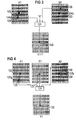
- the pixel 120 in the output field is generated by the median filter 121.
- the example is shown specifically for the field X1Y1 to be generated.
- the pixel point 122 or 123 corresponding to the pixel point 120 is assumed.
- the motion vector 124 determined for this pixel point is plotted on the pixel 122 in the backward movement direction and on the pixel 123 in the forward movement direction.
- the pixel 125 or 126 then obtained is fed into the median filter 121. If, as in the case of the pixel 126, there is a pixel lying outside the raster position, inter-line interpolation is carried out, for example averaging from the immediately adjacent pixels.
- Another input value for the median filter 21 is the luminance value 0.
- the median filter 121 sorts the input values in terms of size and the mean value is selected as the output value. This access scheme in the height channel for uncovered areas ensures that the luminance value of the pixels 125, 126 dominates if the motion vector 124 is error-free. Then it is to be expected that the pixels 125, 126 have approximately the same luminance. If the motion vector 124 for the pixel 120 has been determined incorrectly, it can be assumed that the luminance values of the pixels 125, 126 differ from one another. Then the median filter 121 is more likely to select the permanently fed-in luminance value "0", so that no image information is provided for reproduction at location 120 via the height channel. The pixel point 121 is then that of the deep channel calculated image information dominates. Overall, this median filter is dominant in terms of grid and time, since the input values are selected from pixels that are in the correct grid and are staggered in time.
- a 5-point median filter with multiple weighting of pixels can also be used.
- the image points taken from the fields A1, B1 are weighted twice.
- the immediately adjacent pixels can be used in each case with a simple weighting. The raster dominance of the filter and the generated pixel is increased in this embodiment.
- the pixel information of the pixel corresponding to pixel 120 in field B0 can be fed into the median filter, preferably the 5-point median filter.
- This value has the same raster position as the raster position of the field X1Y1 to be generated and thereby improves the raster-dominant effect of this filter.
- the image point of field B2 corresponding to pixel 120 in median filter 121 must be used in mirror image. The consideration of the image information of the third field B0 or B2 requires additional memory, so that access to the data to be processed of another field is made possible.
- the access scheme for the median filter 131 shown in FIG. 4 is used to calculate the image Y1 converted in the raster position.
- the respective pixels 132, 133, 134 corresponding to the pixels 130 to be generated are used in the fields A1, B1, A2.
- the pixel 133 is transferred to the median filter 131 after an interline interpolation, the pixels 132, 134 apply the motion vector 137 stored for the pixel 130 in the backward or forward direction.
- the luminance values of the resulting pixels 135 and 136 are used as further input values of the median filter 131.
- the motion vector that results between the pixels of the input-side fields B1, A2 is expediently selected as the motion vector 137. This movement vector is already present on the input side or can be calculated in a simple manner from the movement difference between the fields A1, B1 on the input side.
- those image areas of the intermediate images X1Y1 and Y1X2 for which a detection indicator is stored are assigned a luminance of 0, so that only the luminance value determined in the depth channel is taken into account for these pixels in a detection area.
- the field X1 is generated by directly taking over the depth signal portion of the field A1. The same applies to field X2, with which a new cycle begins.
- the field Y1 is calculated by a raster conversion from the depth signal components of only the field B1.
- a linear interline interpolation 141 for example averaging from adjacent pixels, is expediently carried out for the raster conversion.
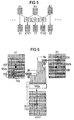
- a motion-compensated Median filtering 142 is carried out, to which the input-side fields A1, B1 or B1, A2 lying adjacent to the intermediate image X1Y1 and Y1X2 in the movement phase are supplied.
- median filtering 142a with 19 input values is carried out in the areas of the depth channel which are not exposed.
- the pixel 150 is generated by the median filtering 142a.
- the pixels 157, 158 corresponding to the pixel 150 in the field A1, B1 are used.
- the motion vector 152 stored for the pixel location 150 is applied to these pixels in the backward direction or forward direction.
- the pixels 153 and 154 result. These pixels 153, 154 are fed five times weighted into the 19-point median filter 142a.
- the surrounding pixels 155 of the pixel 153 are fed in with a simple weighting. The same applies to the pixel 154.
- the luminance value of the pixel 151 is given special weight. In this case, it is desirable that the pixel 150 align with that through the pixel 151 adapts predetermined environment.
- a corresponding access scheme is carried out for the intermediate field Y1X2.
- the median filter 142 is implemented as a 3-point median filter 142b.
- pixel 161 or 162 is selected which corresponds to the pixel 160 of the field X1Y1 to be generated. If a motion vector has been determined in the vicinity of the pixels 161, 162, preferably the immediately surrounding 8 pixels, this motion vector is applied to the pixel 161, 162 in the backward or forward direction of movement. This case is shown in Figure 7.
- the 3-point median filter 142b is fed with the pixel 163 of the field A1 and with the start and end point of the movement in the field B1, i. H. the pixels 162 and 164. If no motion vector can be determined, the pixel 162 is fed twice into the median filter 142b. This is caused by the fact that temporally successive image information is fed into the filter 142b.
- median filtering is carried out by the access schemes shown in FIGS. 6, 7 in the deep channel for undetected or uncovered image areas, which deliver a result that is determined with high probability with the correct movement phase, since in the case of the filtering according to FIG Input pixels dominate and the movement-correct result also dominates in the access diagram of FIG. 6. It is important for movement-correct reproduction in the deep channel that the two access schemes of FIGS. 6, 7 are essentially location-dominant. Due to the local dominance of the filtering according to FIG. 6, the good relapse quality of the statistical median filter method becomes effective in the case of a motion vector with errors. When filtering according to figure 7, a pixel is generated which fits well into the environment due to the takeover of a neighboring vector.
Landscapes
- Engineering & Computer Science (AREA)
- Multimedia (AREA)
- Signal Processing (AREA)
- Television Systems (AREA)
- Image Processing (AREA)
Applications Claiming Priority (2)
| Application Number | Priority Date | Filing Date | Title |
|---|---|---|---|
| DE19505758A DE19505758A1 (de) | 1995-02-20 | 1995-02-20 | Verfahren und Schaltungsanordnung zur Flimmerreduktion für ein Gerät zur Videosignalverarbeitung |
| DE19505758 | 1995-02-20 |
Publications (3)
| Publication Number | Publication Date |
|---|---|
| EP0727904A2 true EP0727904A2 (fr) | 1996-08-21 |
| EP0727904A3 EP0727904A3 (fr) | 1997-10-22 |
| EP0727904B1 EP0727904B1 (fr) | 2002-06-19 |
Family
ID=7754494
Family Applications (1)
| Application Number | Title | Priority Date | Filing Date |
|---|---|---|---|
| EP96101610A Expired - Lifetime EP0727904B1 (fr) | 1995-02-20 | 1996-02-05 | Méthode et arrangement de circuit pour la réduction de scintillation dans un dispositif de traitement de signal vidéo |
Country Status (2)
| Country | Link |
|---|---|
| EP (1) | EP0727904B1 (fr) |
| DE (2) | DE19505758A1 (fr) |
Cited By (5)
| Publication number | Priority date | Publication date | Assignee | Title |
|---|---|---|---|---|
| DE19705775C1 (de) * | 1997-02-14 | 1998-01-02 | Siemens Ag | Verfahren und Schaltungsanordnung zur Flimmerreduktion eines Bildsignals |
| DE19649651C1 (de) * | 1996-11-29 | 1998-01-22 | Siemens Ag | Verfahren und Schaltungsanordnung zum Erzeugen einer Folge von progressiven Bildern |
| US6262774B1 (en) | 1997-10-27 | 2001-07-17 | Infineon Technologies Ag | Method and circuit configuration for producing a sequence of progressive images |
| WO2002005548A1 (fr) * | 2000-07-08 | 2002-01-17 | Bts Holding International B.V. | Dispositif de reduction des scintillements parasites |
| US7315331B2 (en) | 2001-01-09 | 2008-01-01 | Micronas Gmbh | Method and device for converting video signals |
Family Cites Families (3)
| Publication number | Priority date | Publication date | Assignee | Title |
|---|---|---|---|---|
| DE3814570A1 (de) * | 1988-04-29 | 1989-11-09 | Grundig Emv | Verfahren und schaltungsanordnung zur flimmerreduktion bei einem fernsehempfaenger |
| DE59206314D1 (de) * | 1992-02-07 | 1996-06-20 | Siemens Ag | Verfahren und Schaltungsanordnung zur bewegungsvektorgestützten Flimmerreduktion bei einem Fernsehempfänger |
| DE4434728C1 (de) * | 1994-09-28 | 1995-11-02 | Siemens Ag | Verfahren und Schaltungsanordnung zur Flimmerreduktion für ein Gerät zur Videosignalverarbeitung |
-
1995
- 1995-02-20 DE DE19505758A patent/DE19505758A1/de not_active Withdrawn
-
1996
- 1996-02-05 EP EP96101610A patent/EP0727904B1/fr not_active Expired - Lifetime
- 1996-02-05 DE DE59609352T patent/DE59609352D1/de not_active Expired - Fee Related
Cited By (7)
| Publication number | Priority date | Publication date | Assignee | Title |
|---|---|---|---|---|
| DE19649651C1 (de) * | 1996-11-29 | 1998-01-22 | Siemens Ag | Verfahren und Schaltungsanordnung zum Erzeugen einer Folge von progressiven Bildern |
| DE19705775C1 (de) * | 1997-02-14 | 1998-01-02 | Siemens Ag | Verfahren und Schaltungsanordnung zur Flimmerreduktion eines Bildsignals |
| WO1998036562A1 (fr) * | 1997-02-14 | 1998-08-20 | Siemens Aktiengesellschaft | Procede et circuit pour reduire le scintillement d'un signal image |
| US6262774B1 (en) | 1997-10-27 | 2001-07-17 | Infineon Technologies Ag | Method and circuit configuration for producing a sequence of progressive images |
| WO2002005548A1 (fr) * | 2000-07-08 | 2002-01-17 | Bts Holding International B.V. | Dispositif de reduction des scintillements parasites |
| US7466364B2 (en) | 2000-07-08 | 2008-12-16 | Thomson Licensing | Device for reducing flicker defects |
| US7315331B2 (en) | 2001-01-09 | 2008-01-01 | Micronas Gmbh | Method and device for converting video signals |
Also Published As
| Publication number | Publication date |
|---|---|
| EP0727904B1 (fr) | 2002-06-19 |
| DE19505758A1 (de) | 1996-08-22 |
| EP0727904A3 (fr) | 1997-10-22 |
| DE59609352D1 (de) | 2002-07-25 |
Similar Documents
| Publication | Publication Date | Title |
|---|---|---|
| DE69027479T2 (de) | Bewegungsabhängige Videosignalverarbeitung | |
| DE69031055T2 (de) | Bewegungsabhängige Videosignalverarbeitung | |
| DE69022470T2 (de) | Bewegungsabhängige Videosignalverarbeitung. | |
| DE69123359T2 (de) | Videobildverarbeitung | |
| DE69605936T2 (de) | Bewegungskompensierte interpolation | |
| DE69223925T2 (de) | Videobildverarbeitung | |
| DE69422255T2 (de) | Verfahren und Vorrichtung zum bewegungsausgeglichenen Interpolieren von zwischenliegenden Halbbildern oder Bildern | |
| DE3685589T2 (de) | Videosignal-verarbeitung fuer bandbreitenverringerung. | |
| DE69030896T2 (de) | Bewegungsabhängige Videosignalverarbeitung | |
| EP1397915B1 (fr) | Procede et dispositif pour la conversion de signaux video | |
| DE69021431T2 (de) | Bewegungsabhängige Videosignalverarbeitung. | |
| DE69028651T2 (de) | Bewegungsabhängige Videosignalverarbeitung | |
| DE69015419T2 (de) | Umwandlung eines Videosignals auf einen photographischen Film. | |
| DE69510851T2 (de) | Verfahren und Gerät zur Reduzierung von Umwandlungsartefakten | |
| DE69028792T2 (de) | Bewegungsabhängige Videosignalverarbeitung | |
| DE69031144T2 (de) | Bewegungsabhängige Videosignalverarbeitung | |
| DE69027704T2 (de) | Bewegungsabhängige Videosignalverarbeitung | |
| DE69028239T2 (de) | Bewegungsabhängige Videosignalverarbeitung | |
| DE69031322T2 (de) | Bewegungsabhängige Videosignalverarbeitung | |
| EP1770635B1 (fr) | Méthode itérative d'interpolation d'image | |
| EP1125428B1 (fr) | Circuit permettant de transformer un debit binaire | |
| EP0414017B1 (fr) | Procédé de compensation du mouvement orienté d'objet d'information d'image pour la reproduction de sequences d'images animées codées | |
| EP0727904B1 (fr) | Méthode et arrangement de circuit pour la réduction de scintillation dans un dispositif de traitement de signal vidéo | |
| EP0596561B1 (fr) | Dispositif de doublement de la fréquence de trame d'un signal d'image | |
| EP0554495B1 (fr) | Méthode et configuration de circuit pour la réduction du scintillement basée sur le vecteur de mouvement dans un récepteur de télévision |
Legal Events
| Date | Code | Title | Description |
|---|---|---|---|
| PUAI | Public reference made under article 153(3) epc to a published international application that has entered the european phase |
Free format text: ORIGINAL CODE: 0009012 |
|
| AK | Designated contracting states |
Kind code of ref document: A2 Designated state(s): DE ES FR GB IT |
|
| PUAL | Search report despatched |
Free format text: ORIGINAL CODE: 0009013 |
|
| AK | Designated contracting states |
Kind code of ref document: A3 Designated state(s): DE ES FR GB IT |
|
| 17P | Request for examination filed |
Effective date: 19971120 |
|
| 17Q | First examination report despatched |
Effective date: 19990903 |
|
| RAP1 | Party data changed (applicant data changed or rights of an application transferred) |
Owner name: MICRONAS MUNICH GMBH |
|
| GRAG | Despatch of communication of intention to grant |
Free format text: ORIGINAL CODE: EPIDOS AGRA |
|
| GRAG | Despatch of communication of intention to grant |
Free format text: ORIGINAL CODE: EPIDOS AGRA |
|
| GRAH | Despatch of communication of intention to grant a patent |
Free format text: ORIGINAL CODE: EPIDOS IGRA |
|
| GRAH | Despatch of communication of intention to grant a patent |
Free format text: ORIGINAL CODE: EPIDOS IGRA |
|
| GRAA | (expected) grant |
Free format text: ORIGINAL CODE: 0009210 |
|
| AK | Designated contracting states |
Kind code of ref document: B1 Designated state(s): DE ES FR GB IT |
|
| REG | Reference to a national code |
Ref country code: GB Ref legal event code: FG4D Free format text: NOT ENGLISH |
|
| GBT | Gb: translation of ep patent filed (gb section 77(6)(a)/1977) |
Effective date: 20020619 |
|
| REF | Corresponds to: |
Ref document number: 59609352 Country of ref document: DE Date of ref document: 20020725 |
|
| ET | Fr: translation filed | ||
| PG25 | Lapsed in a contracting state [announced via postgrant information from national office to epo] |
Ref country code: ES Free format text: LAPSE BECAUSE OF FAILURE TO SUBMIT A TRANSLATION OF THE DESCRIPTION OR TO PAY THE FEE WITHIN THE PRESCRIBED TIME-LIMIT Effective date: 20021220 |
|
| PLBE | No opposition filed within time limit |
Free format text: ORIGINAL CODE: 0009261 |
|
| STAA | Information on the status of an ep patent application or granted ep patent |
Free format text: STATUS: NO OPPOSITION FILED WITHIN TIME LIMIT |
|
| 26N | No opposition filed |
Effective date: 20030320 |
|
| PGFP | Annual fee paid to national office [announced via postgrant information from national office to epo] |
Ref country code: GB Payment date: 20070223 Year of fee payment: 12 |
|
| PGFP | Annual fee paid to national office [announced via postgrant information from national office to epo] |
Ref country code: DE Payment date: 20070330 Year of fee payment: 12 |
|
| PGFP | Annual fee paid to national office [announced via postgrant information from national office to epo] |
Ref country code: IT Payment date: 20070521 Year of fee payment: 12 |
|
| PGFP | Annual fee paid to national office [announced via postgrant information from national office to epo] |
Ref country code: FR Payment date: 20070221 Year of fee payment: 12 |
|
| GBPC | Gb: european patent ceased through non-payment of renewal fee |
Effective date: 20080205 |
|
| REG | Reference to a national code |
Ref country code: FR Ref legal event code: ST Effective date: 20081031 |
|
| PG25 | Lapsed in a contracting state [announced via postgrant information from national office to epo] |
Ref country code: DE Free format text: LAPSE BECAUSE OF NON-PAYMENT OF DUE FEES Effective date: 20080902 |
|
| PG25 | Lapsed in a contracting state [announced via postgrant information from national office to epo] |
Ref country code: FR Free format text: LAPSE BECAUSE OF NON-PAYMENT OF DUE FEES Effective date: 20080229 |
|
| PG25 | Lapsed in a contracting state [announced via postgrant information from national office to epo] |
Ref country code: GB Free format text: LAPSE BECAUSE OF NON-PAYMENT OF DUE FEES Effective date: 20080205 |
|
| PG25 | Lapsed in a contracting state [announced via postgrant information from national office to epo] |
Ref country code: IT Free format text: LAPSE BECAUSE OF NON-PAYMENT OF DUE FEES Effective date: 20080205 |