EP0728389B1 - Procede de reception d'un signal dans un systeme de telecommunication numerique synchrone - Google Patents
Procede de reception d'un signal dans un systeme de telecommunication numerique synchrone Download PDFInfo
- Publication number
- EP0728389B1 EP0728389B1 EP95900153A EP95900153A EP0728389B1 EP 0728389 B1 EP0728389 B1 EP 0728389B1 EP 95900153 A EP95900153 A EP 95900153A EP 95900153 A EP95900153 A EP 95900153A EP 0728389 B1 EP0728389 B1 EP 0728389B1
- Authority
- EP
- European Patent Office
- Prior art keywords
- pointer
- norm
- state
- new
- lop
- Prior art date
- Legal status (The legal status is an assumption and is not a legal conclusion. Google has not performed a legal analysis and makes no representation as to the accuracy of the status listed.)
- Expired - Lifetime
Links
- 238000000034 method Methods 0.000 title claims description 15
- 230000001360 synchronised effect Effects 0.000 title claims description 12
- 230000007704 transition Effects 0.000 claims description 45
- RGNPBRKPHBKNKX-UHFFFAOYSA-N hexaflumuron Chemical compound C1=C(Cl)C(OC(F)(F)C(F)F)=C(Cl)C=C1NC(=O)NC(=O)C1=C(F)C=CC=C1F RGNPBRKPHBKNKX-UHFFFAOYSA-N 0.000 claims description 3
- 230000008859 change Effects 0.000 description 6
- 230000005540 biological transmission Effects 0.000 description 4
- 238000010586 diagram Methods 0.000 description 4
- 230000008569 process Effects 0.000 description 2
- 238000010276 construction Methods 0.000 description 1
- 230000003247 decreasing effect Effects 0.000 description 1
- 230000006872 improvement Effects 0.000 description 1
- 239000011159 matrix material Substances 0.000 description 1
- 230000007246 mechanism Effects 0.000 description 1
- 230000015654 memory Effects 0.000 description 1
- 230000010363 phase shift Effects 0.000 description 1
- 238000011084 recovery Methods 0.000 description 1
Images
Classifications
-
- H—ELECTRICITY
- H04—ELECTRIC COMMUNICATION TECHNIQUE
- H04J—MULTIPLEX COMMUNICATION
- H04J3/00—Time-division multiplex systems
- H04J3/02—Details
- H04J3/14—Monitoring arrangements
-
- H—ELECTRICITY
- H04—ELECTRIC COMMUNICATION TECHNIQUE
- H04J—MULTIPLEX COMMUNICATION
- H04J2203/00—Aspects of optical multiplex systems other than those covered by H04J14/05 and H04J14/07
- H04J2203/0001—Provisions for broadband connections in integrated services digital network using frames of the Optical Transport Network [OTN] or using synchronous transfer mode [STM], e.g. SONET, SDH
- H04J2203/0057—Operations, administration and maintenance [OAM]
- H04J2203/006—Fault tolerance and recovery
Definitions
- the invention relates to a method according to the preambles of attached claims 1 and 2 for receiving a signal used in a synchronous digital telecommunications system.
- the current digital transmission network is plesiochronous, that is, each 2-Mbit/s basic multiplex system has a dedicated clock independent of any other system. It is therefore impossible to locate a single 2-Mbit/s signal in the bit stream of a higher-order system, but the higher-level signal has to be demultiplexed through each intermediate level down to the 2 Mbit/s level to extract the 2-Mbit/s signal. For this reason, especially the construction of branch connections requiring several multiplexers and demultiplexers has been expensive.
- Another disadvantage of the plesiochronous transmission network is that equipments from two different manufacturers are not usually compatible.
- the above drawbacks have led to the introduction of the new synchronous digital hierarchy SDH specified e.g. in the CCITT recommendations G.707 to G.709 and G.781 to G.784.
- STM-N transfer frames Synchronous Transport Modules
- the bit rates are multiples of the bit rate of the lowest level.
- the SDH telecommunication utilizes a pointer, i.e. a number that indicates the phase of payload within a frame. The pointer thus points that byte in the STM frame from which the payload begins.
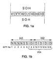
- the STM-N frame comprises a matrix with 9 rows and N x 270 columns so that there is one byte at the junction point between each row and the column.
- Rows 1-3 and rows 5-9 of the N x 9 first columns comprise a section overhead SOH, and the row 4 comprises an AU pointer.
- the rest of the frame structure is formed of a section having the length of N x 261 columns and containing the payload section of the STM-N frame.
- the row of the STM-1 frame is thus 270 bytes in length, as described above.
- the payload section comprises one or more administration units AU.
- Each byte in the AU-4 unit has its own location number.
- the above-mentioned AU pointer contains the location of the first byte of the VC-4 container in the AU-4 unit.
- the pointers allow positive or negative pointer justifications to be performed at different points in the SDH network. If a virtual container having a certain clock frequency is applied to a network node operating at a clock frequency lower than the above-mentioned clock frequency of the virtual container, the data buffer will be filled up. This requires negative justification: one byte is transferred from the received virtual container into the overhead section of the frame to be transmitted while the pointer value is decreased by one. If the rate of the received virtual container is lower than the clock rate of the node, the data buffer tends to be emptied, which calls for positive justification: a stuff byte is added to the received virtual container and the pointer value is incremented by one.
- the SDH system comprises pointers on two levels: AU pointers and TU pointers, which indicate the first byte of a corresponding virtual container VC within the AU or TU unit, respectively.
- AU pointers and TU pointers, which indicate the first byte of a corresponding virtual container VC within the AU or TU unit, respectively.
- TU pointers which indicate the first byte of a corresponding virtual container VC within the AU or TU unit, respectively.
- the CCITT specifications relating to the pointer are set forth in Reference [1], which is referred to for a more detailed description.
- the AU-4 pointer for example, consists of nine successive bytes H1, Y, Y...H3, of which bytes H1 and H2 are shown separately in Figure lb.
- the actual pointer value PTR consists of the ten last bits (bits 7 to 16) of the word formed by bytes H1 and H2.
- the values of the TU-11, TU-12 and TU-2 pointers consist of the ten last bits of the word formed by bytes V1 and V2.
- the TU-3 pointer consists of bytes H1 and H2 in the same way as the AU-4 pointer ( Figure lb).
- the AU and TU pointers have quite similar coding even in other respects; there are, however, some differences, which will be described in the following.
- the pointer value must be within a certain range in order to be acceptable.
- the acceptable decimal value of the AU-4 pointer is from 0 to 782, and the acceptable decimal value of the TU-12 pointer, for example, is from 0 to 139.
- These values are called offset values, as they (within the frame structure) indicate the offset between the pointer and the first byte of the corresponding virtual container.
- the new data flag NDF determined by the N bits allows arbitrary changes in the pointer value if they are the result of a change taking place in the payload.
- Normal operation (NDF_disabled) is indicated by the N-bit values "0110", and the new pointer value (NDF_enable) by the N-bit values "1001" (i.e. by inverting the bits of the normal state).
- NDF_disabled is indicated by the N-bit values "0110”
- NDF_enable by the N-bit values "1001” (i.e. by inverting the bits of the normal state).
- the new data flag together with the new pointer value, indicates a change in the alignment of the virtual container within the frame, if the change is caused by some other reason than positive or negative justification (the transmitter may force a new alignment on the virtual container within the frame structure).
- the new data flag indicates a new pointer value (NDF_enable), and the pointer value consists of one bits (i.e. if bits 1 to 16 are "1001SS1111111111" wherein the S-bits may be independently of one another one or zero), it signifies concatenation.
- Concatenation means that e.g. AU-4 units are concatenated into one larger unit (so-called AU-4-Xc), which may transfer payloads which require a higher capacity than the C-4 container.
- TU-2 units can be concatenated into a larger unit capable of transferring greater payloads than the capacity of the C-2 container).
- the S-bits (bits 5 and 6) indicate on which level of hierarchy (e.g. TU-12) the operation is currently taking place.
- the I- and D-bits of the 10-bit pointer word are used to indicate the positive and negative justification described above. If at least three out of five increment bits, or I-bits (bits 7, 9, 11, 13 and 15), are inverted, it signifies positive justification (if certain additional conditions are met).
- the interpretor of the receiver has three possible main states: the normal state NORM, the alarm state AIS (Alarm Indication Signal), and the loss of pointer state LOP, which will be described more closely below.
- the LOP state transition to the normal state NORM can take place if the same pointer is received three times in succession.
- TU-12 and TU-2 frames this transition thus requires a time period corresponding to at least twelve STM-1 frames, and with TU-3 frames a time period corresponding to at least three STM-1 frames.
- this thus means that the loss of pointer state lasts at least 1,500 ⁇ s, whereas the time period after which the normal state can be resumed may actually be much longer.
- the object of the present invention is to eliminate the above-described drawback and provide a method which speeds up the transition of data transmission back to normal state. This is achieved by means of a method according to the invention, which is characterized by what is described in the characterizing portions of attached claims 1 and 2.
- the idea of the invention is that instead of starting the counting of the new pointer from the beginning, as defined in the CCITT recommendations, on transition from the normal state NORM or alarm state AIS to the loss of pointer state LOP, the counter is allowed to step normally in spite of the state transition, whereby transition back to the normal state NORM will take place clearly more rapidly.
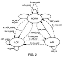
- the pointer interpretation effected in the receiver can be illustrated as a state diagram in which the interpretation machine of the receiver has the above-mentioned main states: the normal state NORM, the alarm state AIS (Alarm Indication Signal), and the loss of pointer state LOP.
- NORM normal state
- AIS Alarm Indication Signal
- LOP loss of pointer state
- NORM state event Definition active_point active pointer
- NDF_disabled new data flag
- SS-bits are correct
- the offset value is within the acceptable range and equal to the valid offset value.
- new_point new pointer
- the new data flag has the value "normal” (NDF_disabled), the SS-bits are correct, and the offset value is within the acceptable range and unequal to the valid offset value.
- NDF_enable new data flag
- the new data flag has the value "new” (NDF_enable), the SS-bits are correct, and the offset value is within the acceptable range.
- AIS_ind AIS alarm
- the 16-bit pointer word has the value "1111 1111 1111 1111”.
- inc_ind increment data
- the new data flag has the value "normal” (NDF_disabled), the SS-bits are correct, the majority of I-bits are inverted, and the majority of D-bits are not inverted, and the value "new" for the new data flag (NDF_enable), increment data (inc_ind) or decrement data (dec_ind) has not been received in the three preceding frames.
- dec_ind (decrement data)
- the new data flag has the value "normal” (MDF_disabled), the SS-bits are correct, and the majority of D-bits are inverted, and the majority of I-bits are not inverted, and the value "new" for the new data flag (NDF_enable), increment data (inc_ind) or decrement data (dec_ind) has not been received in the three preceding frames.
- NORM_inv_point invalid pointer of the NORM state
- AIS state event Definition active_point active pointer
- new_point new pointer
- the new data flag has the value "normal” (NDF_disabled), the SS-bits are correct, and the offset value is within the acceptable range.
- NDF_enable new data flag
- the new data flag has the value "new” (NDF_enable), the SS-bits are correct, and the offset value is within the acceptable range.
- AIS_ind (AIS alarm)
- the 16-bit pointer word has the value "1111 1111 1111 1111".
- NDF_enable new data flag
- the new data flag has the value "new" (NDF_enabled), the SS-bits are correct, and the offset value is within the acceptable range.
- AIS_ind AIS alarm
- the 16-bit pointer word has the value "1111 1111 1111”.
- inc_ind increment data
- dec_ind decrement data
- LOP_inv_point invalid pointer of the LOP state
- the counter of the invalid pointer is not updated at all, or (II) all pointer values that are unequal to the AIS alarm, or (III) all pointer values that are unequal to the AIS alarm and the value "new" for the new data flag.
- the above-mentioned bytes H1 and H2 (bits 1 to 16) of the pointer (or with TU-11, TU-12 and TU-2 pointers, the bytes V1 and V2) can indicate up to seven different events.
- the transition of the receiver between the different main states and to another internal state within a main state is controlled by means of counters as defined in the following table.
- the index (N or 3) at the beginning of the name of the counter indicates the maximum value of the counter.
- the counters are modulo counters, i.e. when the counter value reaches its upper limit, the counter starts over again.
- COUNTER OPERATION N x NDF_enable (NDF counter) wherein (N 8...10) Counts successive NDF_enable events and controls transition from NORM state to LOP state.
- 3 x new_point (counter of the new pointer) Counts successive new_point events and controls transition from LOP and AIS states to NORM state, and from NORM state to NORM state (change in the offset value).
- N x inv_point (counter of an invalid pointer) Counts successive inv_point events and controls transition from NORM and AIS states to LOP state.
- 3 x AIS_ind (alarm counter) Counts successive AIS_ind events and controls transition from NORM and LOP states to AIS state.
- the counter of the new pointer controls the process for finding a correct frame synchronization if the pointer value has been changed erroneously.
- the offset values of three successive new pointers must be equal, otherwise the counter of the new pointer is reset. For this reason, it is likely to require a longer time period than three STM-1 frames (or twelve STM-1 frames if the STM-1 signal contains TU-12 or TU-2 frames).
- N has a value of from 8 to 10.
- Transition from the normal state NORM to the loss of pointer state LOP may also take place when the NDF flag counter achieves its maximum value, which requires N successive NDF_enable events.
- Figure 2 the state transitions described above are indicated by broken lines.
- Figure 2 also illustrates reception of a single new data flag (together with an acceptable pointer value) in the alarm state, which leads to transition to the normal state NORM. This is the only single event which causes transition from one main state to another.
- Figure 2 illustrates other changes occurring in the normal state. Such changes are (1) reception of increment or decrement data inc_ind/dec_ind, and (2) reception of a single new data flag, both of these causing a change in a manner known per se in the offset value in the normal state, and reception of the active pointer (active_point).
- the figure also illustrates internal changes occurring in the AIS and LOP states.
- Finnish Patent Applications 923 061 and 923 062 are referred to, where the interpretation process is illustrated by means of a flow diagram.
- the present invention may utilize either the same interpretation or the same interpretation so modified that each increment or decrement data item is accepted only if the value "new" for the new data flag (NDF_enable), the increment data (inc_ind) or the decrement data (dec_ind) has not been received in the three preceding frames and if the S-bits have been received correctly.
- NDF_enable new data flag
- inc_ind increment data
- decrement data decrement data
- transition from the loss of pointer state LOP back to the normal state requires a time period corresponding to at least twelve STM-1 frames in the case of TU-12 and TU-2 frames and a time period corresponding to at least three STM-1 frames in the case of TU-3 frames.
- this transition is speeded up in a very simple way, i.e. by neglecting that resetting of the counter of the new pointer counting successive new pointers (new_point) which would be caused by transition from NORM state to LOP state.
- transition from LOP state back to NORM state can be accepted in the case of TU-12 and TU-2 frames after four STM-1 frames, and in the case of TU-3 frames after one STM-1 frame in cases shown in the following table.
- the columns on the left side of the table present the interpretation according to the present invention; columns on the right side present, for the sake of comparison, the interpretation according to the CCITT recommendations.
- Successive STM-1 frames have been numbered from 1 to 53.
- the example concerns a case where the STM-1 signal contains TU-12 frames (or TU-11 or TU-2 frames), the received pointer being known after each V2 byte.
- the values of the received pointers are 20, 39, 24, 120, 39, 39, 21, 39, 39, 39, 39, 39 and 39.
- the counter of the new pointer is not reset in the method according to the invention upon transition to the LOP state after frame 33, when the counter of the invalid pointer achieves its upper limit.
- NORM transition back to the normal state NORM takes place when the counter of the new pointer achieves the value three, this transition takes place in the method according to the invention eight STM-1 frames earlier than in the method complying with the CCITT recommendations.
- the improvement in the recovery rate to be achieved by means of the method according to the invention depends on the reading of the counter of the new pointer upon transition to the LOP state. If the counter of the new pointer steps to the value three at the same time as the upper limit of the counter of the invalid pointer is reached, no transition to the LOP state takes place but the pointer interpretation machine remains in normal state.
- the counter of the new pointer counts the number of successive identical new pointers, whereby it steps e.g. at frame 6 to the value l, as the value of the obtained pointer deviates from the preceding value, but it will not step onwards from the value l e.g. at frames 10 and 14, as the obtained pointer values deviate from the preceding values.
- transition to the LOP state results from the counter of the invalid pointer reaching its upper limit.
- the transition may equally well result from the NDF counter reaching its upper limit (cf. Figure 2).
- Both of the above examples concern a case where the LOP state is entered from the NORM state.
- the LOP state may equally well be entered from the alarm state AIS, in which case the resetting of the counter of the new pointer caused by the state transition is neglected when the transition takes place. Both transitions take place if N successive invalid pointers (cf. Figure 2) are received. In the case of the AIS state, this is the only event that causes transition to the LOP state.
- the predetermined number of new pointers after which the normal state (NORM) is entered may vary, particularly if the recommendations are changed in this respect.
Landscapes
- Engineering & Computer Science (AREA)
- Computer Networks & Wireless Communication (AREA)
- Signal Processing (AREA)
- Time-Division Multiplex Systems (AREA)
- Communication Control (AREA)
Claims (2)
- Procédé pour recevoir un signal utilisé dans un système de télécommunications numériques synchrones, comme par exemple les systèmes SDH ou SONET, le signal comportant une structure de bloc avec un nombre prédéterminé d'octets d'une longueur fixe et comprenant un pointeur indiquant la phase de charge utile à l'intérieur de la structure de bloc, dans laquelle l'interprétation du pointeur est réalisée alors qu'un récepteur comporte trois états principaux possibles, le récepteur entrant d'un état principal dans un autre sous le contrôle du comptage du nombre d'événements, les dits états principaux étant un état normal (NORM), un état de perte de pointeur (LOP) et un état d'alarme (AIS), et les dits événements comprenant la réception d'un nouveau pointeur (new_point) indiquant une nouvelle valeur de pointeur, dans laquelle le nombre de nouveaux pointeurs successifs est comptée, et, lorsqu'on se trouve dans l'état de perte de pointeur (LOP), on entre dans l'état normal (NORM) une fois que le nouveau pointeur (new_point) a été reçu un nombre prédéterminé de fois successivement, caractérisé en ce que le comptage des nouveaux pointeurs (new_point) est poursuivi lors de la transition depuis l'état normal (NORM) jusqu'à l'état de perte de pointeur (LOP) indépendamment de la dite transition d'état.
- Procédé pour recevoir un signal utilisé dans un système de télécommunications numériques synchrones, comme par exemple les systèmes SDH ou SONET, le signal comportant une structure de bloc avec un nombre prédéterminé d'octets d'une longueur fixe et comprenant un pointeur indiquant la phase de charge utile à l'intérieur de la structure de bloc, dans laquelle l'interprétation du pointeur est réalisée alors qu'un récepteur comporte trois états principaux possibles, le récepteur entrant d'un état principal dans un autre sous le contrôle du comptage du nombre d'événements, les dits états principaux étant un état normal (NORM), un état de perte de pointeur (LOP) et un état d'alarme (AIS), et les dits événements comprenant la réception d'un nouveau pointeur (new_point) indiquant une nouvelle valeur de pointeur, dans laquelle le nombre de nouveaux pointeurs successifs est comptée, et, lorsqu'on se trouve dans l'état de perte de pointeur (LOP), on entre dans l'état normal (NORM) une fois que le nouveau pointeur (new_point) a été reçu un nombre prédéterminé de fois successivement, caractérisé en ce que le comptage des nouveaux pointeurs (new_point) est poursuivi lors de la transition depuis l'état d'alarme (AIS) jusqu'à l'état de perte de pointeur (LOP) indépendamment de la dite transition d'état.
Applications Claiming Priority (3)
| Application Number | Priority Date | Filing Date | Title |
|---|---|---|---|
| FI935026 | 1993-11-12 | ||
| FI935026A FI94813C (fi) | 1993-11-12 | 1993-11-12 | Menetelmä synkronisessa digitaalisessa tietoliikennejärjestelmässä käytettävän signaalin vastaanottamiseksi |
| PCT/FI1994/000506 WO1995013673A1 (fr) | 1993-11-12 | 1994-11-10 | Procede de reception d'un signal dans un systeme de telecommunication numerique synchrone |
Publications (2)
| Publication Number | Publication Date |
|---|---|
| EP0728389A1 EP0728389A1 (fr) | 1996-08-28 |
| EP0728389B1 true EP0728389B1 (fr) | 2003-07-02 |
Family
ID=8538946
Family Applications (1)
| Application Number | Title | Priority Date | Filing Date |
|---|---|---|---|
| EP95900153A Expired - Lifetime EP0728389B1 (fr) | 1993-11-12 | 1994-11-10 | Procede de reception d'un signal dans un systeme de telecommunication numerique synchrone |
Country Status (6)
| Country | Link |
|---|---|
| US (1) | US5724342A (fr) |
| EP (1) | EP0728389B1 (fr) |
| AU (1) | AU8108594A (fr) |
| DE (1) | DE69432900T2 (fr) |
| FI (1) | FI94813C (fr) |
| WO (1) | WO1995013673A1 (fr) |
Families Citing this family (6)
| Publication number | Priority date | Publication date | Assignee | Title |
|---|---|---|---|---|
| CA2287610A1 (fr) * | 1998-11-03 | 2000-05-03 | Claudio Girardi | Methode et circuit pour ameliorer le traitement de pointeur dans des trames de transmission a hierarchie numerique synchrone (sdh) |
| US6891862B1 (en) * | 1999-04-26 | 2005-05-10 | Nortel Networks Limited | Multiplex hierarchy for high capacity transport systems |
| US6628651B1 (en) * | 2000-04-03 | 2003-09-30 | Tellabs Operations, Inc. | Communication switching techniques with improved frame format |
| ATE400934T1 (de) * | 2003-10-14 | 2008-07-15 | Alcatel Lucent | Verbesserte verwaltung von pointerprozessoren bei verketteter nutzlast in sdh oder sonet rahmen |
| US20060126706A1 (en) * | 2004-12-10 | 2006-06-15 | Kevin Brand | Auto-reboot modem |
| CN113866670B (zh) * | 2021-08-25 | 2024-04-30 | 广东电网有限责任公司广州供电局 | 接地故障警示设备、方法和控制装置 |
Family Cites Families (10)
| Publication number | Priority date | Publication date | Assignee | Title |
|---|---|---|---|---|
| LU87713A1 (de) * | 1989-08-31 | 1990-07-24 | Siemens Ag | Kreuzschaltungsverfahren(cross-connect)fuer stm-1-signale der synchron-digital-multiplexhierarchie |
| JP2723699B2 (ja) * | 1991-07-31 | 1998-03-09 | 日本電気株式会社 | Tu−3ポインター付替処理方式 |
| US5210762A (en) * | 1991-10-02 | 1993-05-11 | Alcatel Network Systems, Inc. | Sonet pointer interpretation system and method |
| ES2111553T3 (es) * | 1991-12-24 | 1998-03-16 | Alsthom Cge Alcatel | Maquina logica para procesar informacion de control de tramas de transmision de telecomunicacion. |
| FI90484C (fi) * | 1992-06-03 | 1999-08-11 | Nokia Telecommunications Oy | Menetelmä ja laite synkronisessa digitaalisessa tietoliikennejärjestelmässä käytettävän elastisen puskurimuistin täyttöasteen valvomiseksi |
| FI91698C (fi) * | 1992-07-01 | 1994-07-25 | Nokia Telecommunications Oy | Menetelmä synkronisessa digitaalisessa tietoliikennejärjestelmässä käytettävän signaalin vastaanottamiseksi |
| FI91692C (fi) * | 1992-07-24 | 1994-07-25 | Nokia Telecommunications Oy | Menetelmä synkronisessa digitaalisessa tietoliikennejärjestelmässä käytettävän signaalin vastaanottamiseksi |
| FI98170C (fi) * | 1992-12-02 | 1997-04-25 | Nokia Telecommunications Oy | Menetelmä synkronisessa digitaalisessa tietoliikennejärjestelmässä käytettävän verkkoelementin testaamiseksi |
| FI93289C (fi) * | 1993-03-16 | 1995-03-10 | Nokia Telecommunications Oy | Menetelmä ehdollisten kytkentöjen ohjaamiseksi synkronisessa digitaalisessa tietoliikennejärjestelmässä |
| US5455832A (en) * | 1993-12-17 | 1995-10-03 | Bell Communications Research, Inc. | Method and system for testing a sonet network element |
-
1993
- 1993-11-12 FI FI935026A patent/FI94813C/fi active IP Right Grant
-
1994
- 1994-11-10 AU AU81085/94A patent/AU8108594A/en not_active Abandoned
- 1994-11-10 WO PCT/FI1994/000506 patent/WO1995013673A1/fr not_active Ceased
- 1994-11-10 DE DE69432900T patent/DE69432900T2/de not_active Expired - Lifetime
- 1994-11-10 US US08/640,936 patent/US5724342A/en not_active Expired - Lifetime
- 1994-11-10 EP EP95900153A patent/EP0728389B1/fr not_active Expired - Lifetime
Also Published As
| Publication number | Publication date |
|---|---|
| DE69432900D1 (de) | 2003-08-07 |
| WO1995013673A1 (fr) | 1995-05-18 |
| EP0728389A1 (fr) | 1996-08-28 |
| AU8108594A (en) | 1995-05-29 |
| FI94813C (fi) | 1995-10-25 |
| DE69432900T2 (de) | 2004-04-15 |
| FI935026A7 (fi) | 1995-05-13 |
| FI935026A0 (fi) | 1993-11-12 |
| US5724342A (en) | 1998-03-03 |
| FI94813B (fi) | 1995-07-14 |
Similar Documents
| Publication | Publication Date | Title |
|---|---|---|
| EP0788695B1 (fr) | Methodes pour desassembler et assembler des structures de trames contenant des pointeurs | |
| IE904295A1 (en) | Method for transmitting a digital broadband signal in a¹tributary unit concatenation via a network of a synchronous¹digital multiplex hierarchy | |
| US5539750A (en) | Method for receiving a signal used in a synchronous digital telecommunication system | |
| EP0645065B1 (fr) | Methode et equipement pour surveiller la vitesse de remplissage d'une memoire tampon elastique dans un systeme de telecommunication numerique synchrone | |
| EP0689744B1 (fr) | Procede de gestion de raccordements conditionnels dans un systeme de telecommunication numerique synchrone | |
| EP0728389B1 (fr) | Procede de reception d'un signal dans un systeme de telecommunication numerique synchrone | |
| EP0648394B1 (fr) | Procede de reception d'un signal utilise dans un systeme de telecommunication numerique synchrone | |
| EP0699363B1 (fr) | Procede et dispositif permettant la prise d'une decision de justification au niveau d'un systeme de telecommunication numerique | |
| WO1994003000A1 (fr) | Procede de reception d'un signal utilise dans un systeme de telecommunications numerique synchrone | |
| EP1040708B1 (fr) | Insertion d'une pluralite de contenants virtuels d'ordre superieur a l'interieurd'une trame stm d'ordre superieur dans un systeme sdh | |
| KR100201332B1 (ko) | 동기식 다중화장치에서 vc1 자국 루프백회로 | |
| Rate et al. | 524 ADVANCED BROADBAND DIGITAL TRANSPORT FORMATS Table 17.2 SDH Bit Rates with SONET Equivalents | |
| KR19980015804A (ko) | 동기식 다중화장치의 ds1 매핑 회로 | |
| HK1002380B (en) | Method for disassembling and assembling frame structures containing pointers | |
| HK1011805B (en) | Method and equipment for monitoring the fill rate of an elastic buffer memory in a synchronous digital telecommunication system | |
| KR19980015809A (ko) | 동기식 다중화장치의 ds1e 매핑 회로 |
Legal Events
| Date | Code | Title | Description |
|---|---|---|---|
| PUAI | Public reference made under article 153(3) epc to a published international application that has entered the european phase |
Free format text: ORIGINAL CODE: 0009012 |
|
| 17P | Request for examination filed |
Effective date: 19960422 |
|
| AK | Designated contracting states |
Kind code of ref document: A1 Designated state(s): DE DK FR GB IT NL SE |
|
| RAP1 | Party data changed (applicant data changed or rights of an application transferred) |
Owner name: NOKIA TELECOMMUNICATIONS OY |
|
| RAP1 | Party data changed (applicant data changed or rights of an application transferred) |
Owner name: NOKIA NETWORKS OY |
|
| RAP1 | Party data changed (applicant data changed or rights of an application transferred) |
Owner name: NOKIA CORPORATION |
|
| GRAG | Despatch of communication of intention to grant |
Free format text: ORIGINAL CODE: EPIDOS AGRA |
|
| 17Q | First examination report despatched |
Effective date: 20020611 |
|
| GRAG | Despatch of communication of intention to grant |
Free format text: ORIGINAL CODE: EPIDOS AGRA |
|
| GRAH | Despatch of communication of intention to grant a patent |
Free format text: ORIGINAL CODE: EPIDOS IGRA |
|
| GRAH | Despatch of communication of intention to grant a patent |
Free format text: ORIGINAL CODE: EPIDOS IGRA |
|
| GRAA | (expected) grant |
Free format text: ORIGINAL CODE: 0009210 |
|
| AK | Designated contracting states |
Designated state(s): DE DK FR GB IT NL SE |
|
| PG25 | Lapsed in a contracting state [announced via postgrant information from national office to epo] |
Ref country code: NL Free format text: LAPSE BECAUSE OF FAILURE TO SUBMIT A TRANSLATION OF THE DESCRIPTION OR TO PAY THE FEE WITHIN THE PRESCRIBED TIME-LIMIT Effective date: 20030702 Ref country code: IT Free format text: LAPSE BECAUSE OF FAILURE TO SUBMIT A TRANSLATION OF THE DESCRIPTION OR TO PAY THE FEE WITHIN THE PRE;WARNING: LAPSES OF ITALIAN PATENTS WITH EFFECTIVE DATE BEFORE 2007 MAY HAVE OCCURRED AT ANY TIME BEFORE 2007. THE CORRECT EFFECTIVE DATE MAY BE DIFFERENT FROM THE ONE RECORDED.SCRIBED TIME-LIMIT Effective date: 20030702 |
|
| REG | Reference to a national code |
Ref country code: GB Ref legal event code: FG4D |
|
| REF | Corresponds to: |
Ref document number: 69432900 Country of ref document: DE Date of ref document: 20030807 Kind code of ref document: P |
|
| PG25 | Lapsed in a contracting state [announced via postgrant information from national office to epo] |
Ref country code: SE Free format text: LAPSE BECAUSE OF FAILURE TO SUBMIT A TRANSLATION OF THE DESCRIPTION OR TO PAY THE FEE WITHIN THE PRESCRIBED TIME-LIMIT Effective date: 20031002 Ref country code: DK Free format text: LAPSE BECAUSE OF FAILURE TO SUBMIT A TRANSLATION OF THE DESCRIPTION OR TO PAY THE FEE WITHIN THE PRESCRIBED TIME-LIMIT Effective date: 20031002 |
|
| NLV1 | Nl: lapsed or annulled due to failure to fulfill the requirements of art. 29p and 29m of the patents act | ||
| ET | Fr: translation filed | ||
| PLBE | No opposition filed within time limit |
Free format text: ORIGINAL CODE: 0009261 |
|
| STAA | Information on the status of an ep patent application or granted ep patent |
Free format text: STATUS: NO OPPOSITION FILED WITHIN TIME LIMIT |
|
| 26N | No opposition filed |
Effective date: 20040405 |
|
| REG | Reference to a national code |
Ref country code: GB Ref legal event code: 732E |
|
| REG | Reference to a national code |
Ref country code: FR Ref legal event code: TP |
|
| PGFP | Annual fee paid to national office [announced via postgrant information from national office to epo] |
Ref country code: FR Payment date: 20121113 Year of fee payment: 19 Ref country code: DE Payment date: 20121130 Year of fee payment: 19 |
|
| PGFP | Annual fee paid to national office [announced via postgrant information from national office to epo] |
Ref country code: GB Payment date: 20121025 Year of fee payment: 19 |
|
| GBPC | Gb: european patent ceased through non-payment of renewal fee |
Effective date: 20131110 |
|
| REG | Reference to a national code |
Ref country code: FR Ref legal event code: ST Effective date: 20140731 |
|
| REG | Reference to a national code |
Ref country code: DE Ref legal event code: R119 Ref document number: 69432900 Country of ref document: DE Effective date: 20140603 |
|
| PG25 | Lapsed in a contracting state [announced via postgrant information from national office to epo] |
Ref country code: DE Free format text: LAPSE BECAUSE OF NON-PAYMENT OF DUE FEES Effective date: 20140603 |
|
| PG25 | Lapsed in a contracting state [announced via postgrant information from national office to epo] |
Ref country code: FR Free format text: LAPSE BECAUSE OF NON-PAYMENT OF DUE FEES Effective date: 20131202 Ref country code: GB Free format text: LAPSE BECAUSE OF NON-PAYMENT OF DUE FEES Effective date: 20131110 |