EP0728442A2 - Capnometer - Google Patents
Capnometer Download PDFInfo
- Publication number
- EP0728442A2 EP0728442A2 EP96102759A EP96102759A EP0728442A2 EP 0728442 A2 EP0728442 A2 EP 0728442A2 EP 96102759 A EP96102759 A EP 96102759A EP 96102759 A EP96102759 A EP 96102759A EP 0728442 A2 EP0728442 A2 EP 0728442A2
- Authority
- EP
- European Patent Office
- Prior art keywords
- concentration
- carbon dioxide
- sound
- dioxide concentration
- signal
- Prior art date
- Legal status (The legal status is an assumption and is not a legal conclusion. Google has not performed a legal analysis and makes no representation as to the accuracy of the status listed.)
- Withdrawn
Links
Images


Classifications
-
- A—HUMAN NECESSITIES
- A61—MEDICAL OR VETERINARY SCIENCE; HYGIENE
- A61B—DIAGNOSIS; SURGERY; IDENTIFICATION
- A61B5/00—Measuring for diagnostic purposes; Identification of persons
- A61B5/08—Measuring devices for evaluating the respiratory organs
- A61B5/083—Measuring rate of metabolism by using breath test, e.g. measuring rate of oxygen consumption
- A61B5/0836—Measuring rate of CO2 production
-
- A—HUMAN NECESSITIES
- A61—MEDICAL OR VETERINARY SCIENCE; HYGIENE
- A61B—DIAGNOSIS; SURGERY; IDENTIFICATION
- A61B5/00—Measuring for diagnostic purposes; Identification of persons
- A61B5/74—Details of notification to user or communication with user or patient; User input means
- A61B5/7405—Details of notification to user or communication with user or patient; User input means using sound
- A61B5/7415—Sound rendering of measured values, e.g. by pitch or volume variation
Definitions
- the invention relates to a capnometer which, when carbon dioxide is to be measured, outputs a sound corresponding to the carbon dioxide concentration.
- a capnometer which measures the carbon dioxide concentration of expiration of a patient to be first-aided is used as means for checking that the airway of the patient is open.
- a prior art capnometer comprises a bar-graph indicator which uses light emitting devices such as LEDs, as concentration indicating means, and is configured in such a manner that the length of the bar varies depending on the carbon dioxide concentration in the expiration of the patient.
- Numerals indicating a scale of the carbon dioxide concentration are printed in the side portion of the bar-graph indicator so that the carbon dioxide concentration in the expiration can be read.
- the capnometer of the present invention is an equipment which detects a signal which varies in accordance with a carbon dioxide concentration in a respiration gas.
- the capnometer comprises: carbon dioxide concentration calculating means for detecting a concentration signal corresponding to a carbon dioxide concentration for each expiration, for comparing the concentration signal with concentrations respectively corresponding to a plurality of predetermined concentration ranges, and for outputting one of different control signals for the concentration ranges; and beeper means for outputting a sound corresponding to the carbon dioxide concentration, in accordance with the control signal.
- the beeper means outputs an intermittent sound for each respiration in response to the control signal, the intermittent sound having one of different interruption numbers which are predetermined in accordance with the concentration ranges.
- the beeper means comprises means for converting a level of the concentration signal into a frequency corresponding to the level, and the beeper means outputs a sound for each respiration in response to the control signal, the sound having one of frequencies which are predetermined in accordance with the concentration ranges.
- the beeper means comprises means for converting a level of the concentration signal into a frequency corresponding to the level, and outputs a sound for each respiration, the sound having grequencies which are corresponding to the change of the carbon dioxide concentration.
- the carbon dioxide concentration calculating means detects the maximum value for each expiration from a concentration signal corresponding to a carbon dioxide concentration for each expiration, compares the value with concentrations respectively corresponding to a plurality of predetermined concentration ranges, and outputs one of different control signals for the concentration ranges, and the beeper means outputs a sound in accordance with the control signal.
- the beeper means outputs an intermittent sound for each respiration in response to the control signal, the intermittent sound having one of different interruption numbers which are predetermined in accordance with the concentration ranges.
- the beeper means is provided with means for converting a level of the concentration signal into a frequency corresponding to the level, and the beeper means outputs a sound for each respiration in response to the control signal, the sound having one of frequencies which are predetermined in accordance with the concentration ranges.
- the beeper means is provided with means for converting a level of the concentration signal into a frequency corresponding to the level, and outputs a sound for each respiration, the sound corresponding to the change of the carbon dioxide concentration.
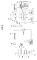
- Figs. 1 and 2 are block diagrams showing the configuration of embodiments of the invention
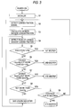
- Fig. 3 is a flowchart showing the procedure of the embodiment of Fig. 1
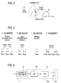
- Fig. 4 is a waveform chart of a carbon dioxide concentration and showing a peak detected for each expiration
- Fig. 5 shows four report examples in the embodiment of Fig. 1
- Fig. 6 is a schematic block diagram showing the main portions of another embodiment of Fig. 1
- Fig. 7 shows four report examples in another embodiment of Fig. 6
- Fig. 8 shows another report example in the other embodiment of Fig. 6,
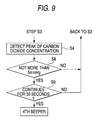
- Fig. 9 is a flowchart showing the procedure in detection of apnea in the report example of Fig. 8.
- Fig. 1, 1 designates a concentration signal detection unit comprising a light source 2 emitting infrared radiation, an airway adapter T, and an infrared sensor 3 which consists of, for example, a thermopile and opposes the light source 2 via the airway adapter T.
- a filter F for a wavelength (about 4.3 ⁇ m) which can be absorbed by carbon dioxide in an expiration gas is disposed on the light sensing area of the infrared sensor 3.
- windows W1 and W2 which are made of an optically transparent material such as a plastic sheet and subjected to an antifogging process are formed at portions which correspond to the light source 2 and the infrared sensor 3, respectively, so that infrared rays from the light source 2 reach the infrared sensor 3.
- One end (the left end in the figure) of the airway adapter T serves as an insertion end which is to be inserted into the mouse of a patient, and the other end (the right end in the figure) serves as an end which is opened in the air.
- the other end may be connected to a bag or a ventilator.
- the reference numeral 4 designates a light source driving unit which consists of, for example, a constant-current circuit and is turned on/off by a switch SW.
- the switch SW consists of a semiconductor switch such as a transistor and is turned on/off at a predetermined period by a control signal output from a controller 8 which will be described later.
- the switch SW is disposed in order to compensate a drift of the output voltage and a change in sensitivity which are caused by variation in ambient temperature or fogging of the windows W1 and W2, and turned on/off, for example, for each respiration (inspiration and expiration) or every one minute.
- the reference numeral 5 designates an amplifier which amplifies the detection voltage of the infrared sensor 3, and 6 designates an analog/digital converter which converts the output of the amplifier 5 into a digital signal.
- the reference numeral 7 designates a carbon dioxide concentration calculation unit which comprises the controller 8 consisting of a CPU, a RAM 9, and a ROM 10.
- the calculation unit compensates the drift of the output voltage and the sensitivity of the infrared sensor 3, calculates the carbon dioxide concentration, and detects the peak value of a concentration signal corresponding to the calculated carbon dioxide concentration.
- the RAM 9 temporarily stores preset data, process data, etc.
- the carbon dioxide concentration calculation unit 7 sends the control signal to a sound indicator 12 which will be described later, on the basis of a result of a comparison of the calculated carbon dioxide concentration and a plurality of carbon dioxide concentration ranges previously set in the control program of the ROM 10.
- the reference numeral 11 designates an operation unit which consists of, for example, a plurality of buttons and through which parameters such as the on/off period of the light source 2, required data, and the like are set.
- the reference numeral 12 designates the sound indicator which consists of a sound device such as a buzzer or a loudspeaker and which is caused to output a sound for each respiration by the control signal output from the carbon dioxide concentration calculation unit 7 and corresponding to the carbon dioxide concentration.
- the reference numeral 13 designates an optical display unit in which, for example, a plurality of LEDs (light emitting diodes) are linearly arranged so as to display a bar graph and numerals respectively corresponding to carbon dioxide concentrations are attached to a side portion by printing or the like.
- a known display unit may be used as the optical display unit 13 which conducts the bar-graph display.
- Fig. 2 shows the configuration of a capnometer which is another embodiment and comprises a drift compensation device.
- 20 designates a connection tube through which a respiration gas passes.
- One end of the connection tube is a connection end which is to be held in the mouth of the subject, and the other end is branched into two parts one of which is opened and the other of which is connected to a servo ventilator 21 for supplying air to the patient in inspiration.
- a pair of optically transparent windows 24a and 24b which are made of glass or the like are formed at the intermediate portion of the connection tube 20.
- a light source 22 is disposed below the window 24b, and a radiation interrupter 25 having an optical through hole and rotated by a motor M is disposed above the window 24a.
- a filter 26 which passes only light of a wavelength which can be absorbed by carbon dioxide is disposed above the optical interrupter 25.
- An optical detector 27 is disposed above the filter 26.
- the reference numeral 28 is an amplifier which amplifies the output voltage of the optical detector 27, and 29 designates a rectifier.
- the reference numeral 32 designates a divider, 33 designates a logarithmic amplifier, and 34 designates a recorder.
- the reference numeral 30 designates an FET (field effect transistor) which is turned on during each inspiration period by the output of the servo ventilator 21, and 31 designates a memory which holds the voltage corresponding to carbon dioxide concentration of "0" during an inspiration period, and outputs the voltage to the divider 32.
- light emitted from the light source 22 passes through the window 24a and a respiration gas in the connection tube 20, and then enters the optical detector 27 via the window 24a and the filter 26 in the form of light interrupted by the optical interrupter 25.
- the optical detector 27 detects the amount of light which corresponds to the carbon dioxide concentration.
- the output signal is amplified by the amplifier 28 and then rectified by the rectifier 29.
- the output of the optical detector 27 contains a change in amount of light due to contamination of the filter 26 and the windows 24a and 24b, and a drift such as variation in light intensity of the light source 22.
- the servo ventilator 21 outputs a positive voltage during an inspiration period to the FET 30 so that the FET is turned on.
- the voltage corresponding to carbon dioxide concentration of "0" is held by the memory 31 and output to the divider 32.
- the servo ventilator 21 ceases from outputting the positive voltage, with the result that the FET 30 is turned off and the output (the signal corresponding to carbon dioxide in the expiration) is supplied to the divider 32.
- the output is divided by the voltage corresponding to carbon dioxide concentration of "0" which is held by the memory 31, so that the drift component is eliminated from the output, thereby calibrating the zero point.
- the output of the divider 32 is supplied to the logarithmic amplifier 33 to obtain an output signal which is proportional to the carbon dioxide concentration.
- the obtained output signal is sent to the carbon dioxide concentration calculation unit 7. Thereafter, the signal and report processes may be conducted in the same manner as those of the embodiment of Fig. 1.
- step S1 the power source is turned on and the eequipment is initialized.
- infrared rays from the light source 2 are passed through a respiration gas passing through the airway adapter T, and the infrared sensor 3 detects light corresponding to the concentration of carbon dioxide contained in the gas and outputs the concentration signal (step S2).
- the concentration signal is sent to the carbon dioxide concentration calculation unit 7 via the amplifier 5 and the analog/digital converter 6 and the carbon dioxide concentration is calculated (step S3).
- step S4 the peak of the carbon dioxide concentration is detected for each expiration.
- peaks P1 and P2 are respectively detected for expirations from the calculated carbon dioxide concentration, by the controller 8.
- step S5 When the carbon dioxide concentration exceeds 20 mmHg (step S5), the controller 8 outputs a control signal for the 1st beeper to the sound indication unit 12 so that an intermittent sound shown in Fig. 5A is produced.
- the 1st beeper for example, an intermittent sound consisting of three continuation periods and two intervals is produced for each respiration. Each of the periods and intervals continues for 50 ms.
- step S6 When the carbon dioxide concentration exceeds 10 mmHg and is not greater than 20 mmHg (step S6), the controller 8 outputs a control signal for the 2nd beeper to the sound indicator unit 12 so that an intermittent sound shown in Fig. 5B is produced.
- the 2nd beeper for example, an intermittent sound consisting of two continuation periods and one interval is produced for each respiration. Each of the periods and intervals continues for 50 ms.
- step S7 When the carbon dioxide concentration exceeds 5 mmHg and is not greater than 10 mmHg (step S7), the controller 8 outputs a control signal for report 3 to the sound indicator unit 12 so that a sound shown in Fig. 5C is produced.
- the 3rd beeper for example, a single sound continuing for 50 ms is produced for each expiration.
- step S8 When the carbon dioxide concentration is not greater than 5 mmHg or a dangerous condition occurs (step S8), it is judged whether the duration of the condition exceeds 30 seconds or not (step S9). If the condition continues for 30 seconds or longer, it is judged that the patient is in an apnea state, and the controller 8 outputs a control signal for the 4th beeper to the sound indicator 12 so that a sound shown in Fig. 5D is produced. In the 4th beeper, two sounds each of which consists of two continuation periods of 50 ms and one interval of 50 ms are produced at an interval of 800 ms, thereby warning the emergency condition.
- step S8 If it is judged in step S8 that the carbon dioxide concentration is greater than 5 mmHg, the process returns to step S2 and the above procedure is repeated. If the duration of the condition in which the carbon dioxide concentration is 5 mmHg or less is shorter than 30 seconds, the process returns to step S2 and the above procedure is repeated.
- the carbon dioxide concentration data which is calculated in step S3 is supplied to the optical display unit 13 and, in the same manner as the prior art, the carbon dioxide concentration in respiration is always displayed in the form of a bar graph which expands or contracts in accordance with the concentration.
- the interruption number of the intermittent sound in respiration is changed in accordance with the change of the carbon dioxide concentration, thereby enabling the carbon dioxide concentration to be judged.
- Fig. 6 is a schematic diagram showing the main portions of another embodiment. The portions corresponding to those of the embodiment of Fig. 1 are designated by the same reference numerals. Also the carbon dioxide concentration calculation unit 33 and the display units 38 and 39 in the embodiment of Fig. 2 can operate in the same manner.
- the sound indicator 12 comprises a digital/analog converter 12a, a voltage controlled oscillator (VCO) 12b which converts the concentration signal into a frequency, and a sound device 12c which outputs a sound and consists of, for example, a buzzer or a small loudspeaker.
- VCO voltage controlled oscillator
- the controller 8 outputs a concentration signal corresponding to the carbon dioxide concentration.
- the concentration signal is converted into an analog signal by the digital/analog converter 12a, and the analog concentration signal is sent to the VCO 12b which in turn converts the concentration signal into a frequency and outputs it to the sound device 12c.
- the sound device 12c produces a sound of the frequency which corresponds to the concentration signal. For example, a sound of a high frequency is produced when the carbon dioxide concentration is high, and a sound of a low frequency is produced when the carbon dioxide concentration is low.
- the processes of judging the carbon dioxide concentration are the same as steps S5 to S9 in the above-described flowchart of Fig. 3 and hence their description is omitted.
- Fig. 7 shows four examples of the sound produced by the sound device 12c (Fig. 6).
- 1st beeper is conducted so that a single sound of, for example, 3 kHz is produced for 200 ms for each respiration (Fig. 7A).
- 2nd beeper is conducted so that a single sound of, for example, 1 kHz is produced for 200 ms (Fig. 7B).
- 3rd beeper is conducted so that a single sound of, for example, 750 Hz is produced for 200 ms (Fig. 7C).
- Fig. 8 shows another beeper example in a second embodiment of Fig. 6.
- one of sounds of different frequencies is continuously produced in accordance with the carbon dioxide concentration which changes in expiration.
- the carbon dioxide concentration in expiration is higher, a continuous sound of a higher frequency is produced.
- the operation is conducted in the reversed manner.
- Fig. 9 is a flowchart showing the procedure of the 4th beeper in a third embodiment of Fig. 6.
- the process proceeds from step S4 of detecting the peak value of the carbon dioxide concentration in the flowchart of Fig. 3, to step S8 in which it is judged whether the carbon dioxide concentration is not greater than 5 mmHg or not.
- the procedure is identical with that of the flowchart of Fig. 3.
- a continuous sound is produced in accordance with the change of the carbon dioxide concentration, and hence the controller 8 of the carbon dioxide concentration calculation unit 7 does not conduct the judgment process for the 1st to 3rd beeper corresponding to steps S5 to S7.
- one of sounds of different frequencies is continuously produced for each respiration in accordance with the carbon dioxide concentration, and therefore the respiration state of the patient can be easily known.
- the peak of the carbon dioxide concentration is detected for each expiration.
- the end tidal volume may be used in place of the peak value.
- ranges of the carbon dioxide concentration are previously determined, and one of sounds respectively corresponding to the ranges is produced, whereby the condition of the carbon dioxide concentration in respiration of a patient can be audible known. Therefore, the invention is effective in judgment of the carbon dioxide concentration of a patient in the nighttime or at dark place.
- a sound is produced for each respiration in accordance with the change of the carbon dioxide concentration, thereby providing an effect that existence of respiration can be easily known.
Landscapes
- Health & Medical Sciences (AREA)
- Life Sciences & Earth Sciences (AREA)
- Biomedical Technology (AREA)
- Heart & Thoracic Surgery (AREA)
- Veterinary Medicine (AREA)
- Physics & Mathematics (AREA)
- Public Health (AREA)
- Biophysics (AREA)
- Pathology (AREA)
- Engineering & Computer Science (AREA)
- General Health & Medical Sciences (AREA)
- Animal Behavior & Ethology (AREA)
- Medical Informatics (AREA)
- Molecular Biology (AREA)
- Surgery (AREA)
- Physiology (AREA)
- Emergency Medicine (AREA)
- Obesity (AREA)
- Pulmonology (AREA)
- Measurement Of The Respiration, Hearing Ability, Form, And Blood Characteristics Of Living Organisms (AREA)
- Investigating Or Analysing Biological Materials (AREA)
Applications Claiming Priority (2)
| Application Number | Priority Date | Filing Date | Title |
|---|---|---|---|
| JP34967/95 | 1995-02-23 | ||
| JP03496795A JP3273295B2 (ja) | 1995-02-23 | 1995-02-23 | 炭酸ガス濃度測定装置 |
Publications (2)
| Publication Number | Publication Date |
|---|---|
| EP0728442A2 true EP0728442A2 (de) | 1996-08-28 |
| EP0728442A3 EP0728442A3 (de) | 1997-01-08 |
Family
ID=12428923
Family Applications (1)
| Application Number | Title | Priority Date | Filing Date |
|---|---|---|---|
| EP96102759A Withdrawn EP0728442A3 (de) | 1995-02-23 | 1996-02-23 | Capnometer |
Country Status (3)
| Country | Link |
|---|---|
| US (1) | US5738106A (de) |
| EP (1) | EP0728442A3 (de) |
| JP (1) | JP3273295B2 (de) |
Cited By (1)
| Publication number | Priority date | Publication date | Assignee | Title |
|---|---|---|---|---|
| EP0733341A3 (de) * | 1995-02-24 | 1998-11-04 | Nihon Kohden Corporation | Kapnometer |
Families Citing this family (29)
| Publication number | Priority date | Publication date | Assignee | Title |
|---|---|---|---|---|
| US6039697A (en) * | 1998-03-20 | 2000-03-21 | Datex-Ohmeda, Inc. | Fiber optic based multicomponent infrared respiratory gas analyzer |
| AU5392499A (en) | 1998-08-03 | 2000-02-28 | James R. Mault | Method and apparatus for respiratory gas analysis employing measurement of expired gas mass |
| EP1115448A4 (de) * | 1998-09-23 | 2002-05-08 | Univ Johns Hopkins | Notfall-überlebenssystem |
| NZ524990A (en) * | 2000-09-28 | 2005-02-25 | Invacare Corp | Carbon dioxide-based BI-level CPAP control |
| AUPR733901A0 (en) * | 2001-08-29 | 2001-09-20 | Watson, Marcus | Method and means of physiological monitoring |
| US7052470B2 (en) * | 2002-02-11 | 2006-05-30 | Gannon Mark D | Breathing detection/confirmation device |
| WO2003098385A2 (en) * | 2002-05-13 | 2003-11-27 | Scott Laboratories, Inc. | System and method for transparent early detection, warning, and intervention during a medical procedure |
| US6863068B2 (en) * | 2002-07-25 | 2005-03-08 | Draeger Medical, Inc. | Ventilation sound detection system |
| US7152598B2 (en) * | 2003-06-23 | 2006-12-26 | Invacare Corporation | System and method for providing a breathing gas |
| US7621270B2 (en) * | 2003-06-23 | 2009-11-24 | Invacare Corp. | System and method for providing a breathing gas |
| US7967759B2 (en) * | 2006-01-19 | 2011-06-28 | Boston Scientific Scimed, Inc. | Endoscopic system with integrated patient respiratory status indicator |
| EP1996222A2 (de) * | 2006-03-23 | 2008-12-03 | Amylin Pharmaceuticals, Inc. | Endothelin und endothelin-rezeptoragonisten bei der behandlung von stoffwechselkrankheiten |
| NL1032880C2 (nl) * | 2006-11-16 | 2008-05-19 | Berkin Bv | Coriolis massa debietmeter. |
| AU2008240290A1 (en) * | 2007-04-13 | 2008-10-23 | Invacare Corporation | Apparatus and method for providing positive airway pressure |
| US8261742B2 (en) | 2007-08-23 | 2012-09-11 | Invacare Corporation | Method and apparatus for adjusting desired pressure in positive airway pressure devices |
| US8771204B2 (en) | 2008-12-30 | 2014-07-08 | Masimo Corporation | Acoustic sensor assembly |
| US8821415B2 (en) | 2009-10-15 | 2014-09-02 | Masimo Corporation | Physiological acoustic monitoring system |
| US8702627B2 (en) | 2009-10-15 | 2014-04-22 | Masimo Corporation | Acoustic respiratory monitoring sensor having multiple sensing elements |
| WO2011047216A2 (en) | 2009-10-15 | 2011-04-21 | Masimo Corporation | Physiological acoustic monitoring system |
| US8523781B2 (en) | 2009-10-15 | 2013-09-03 | Masimo Corporation | Bidirectional physiological information display |
| GB2487882B (en) | 2009-12-04 | 2017-03-29 | Masimo Corp | Calibration for multi-stage physiological monitors |
| JP5358414B2 (ja) * | 2009-12-04 | 2013-12-04 | 株式会社豊田中央研究所 | 漫然状態判定装置、方法及びプログラム |
| US9326712B1 (en) | 2010-06-02 | 2016-05-03 | Masimo Corporation | Opticoustic sensor |
| US9192351B1 (en) | 2011-07-22 | 2015-11-24 | Masimo Corporation | Acoustic respiratory monitoring sensor with probe-off detection |
| EP3603502B1 (de) | 2011-10-13 | 2023-10-04 | Masimo Corporation | Physiologisches akustisches überwachungssystem |
| US9955937B2 (en) | 2012-09-20 | 2018-05-01 | Masimo Corporation | Acoustic patient sensor coupler |
| JP2015000110A (ja) * | 2013-06-13 | 2015-01-05 | 日本光電工業株式会社 | 生体情報モニタ |
| US10828007B1 (en) | 2013-10-11 | 2020-11-10 | Masimo Corporation | Acoustic sensor with attachment portion |
| JP6511501B2 (ja) * | 2017-10-27 | 2019-05-15 | 日本光電工業株式会社 | 生体情報モニタ |
Citations (1)
| Publication number | Priority date | Publication date | Assignee | Title |
|---|---|---|---|---|
| US4576178A (en) * | 1983-03-28 | 1986-03-18 | David Johnson | Audio signal generator |
Family Cites Families (15)
| Publication number | Priority date | Publication date | Assignee | Title |
|---|---|---|---|---|
| US3565058A (en) * | 1967-10-04 | 1971-02-23 | Peter B Mansfield | Monitoring apparatus with audio output frequency responsive to ekg signal amplitude |
| DE2520197C2 (de) * | 1975-05-06 | 1983-11-17 | Siemens AG, 1000 Berlin und 8000 München | Anordnung zur Driftkompensierung eines Gasanalysators |
| JPS5353184A (en) * | 1976-10-22 | 1978-05-15 | Sanei Sokki Kk | Method of indicating living body information |
| US4269194A (en) * | 1978-02-13 | 1981-05-26 | Rayburn Robert L | Carbon dioxide measurement from expired gases in a partial rebreathing anesthesia circuit |
| US4423739A (en) * | 1981-08-24 | 1984-01-03 | Andros Analyzers Incorporated | End tidal carbon dioxide gas analyzer |
| JPS59160446A (ja) * | 1982-09-02 | 1984-09-11 | ネルコ−・インコ−ポレ−テツド | オキシメータ装置 |
| US4653498A (en) * | 1982-09-13 | 1987-03-31 | Nellcor Incorporated | Pulse oximeter monitor |
| US4907166A (en) * | 1986-10-17 | 1990-03-06 | Nellcor, Inc. | Multichannel gas analyzer and method of use |
| US5095913A (en) * | 1989-09-01 | 1992-03-17 | Critikon, Inc. | Shutterless optically stabilized capnograph |
| US5081998A (en) * | 1989-09-01 | 1992-01-21 | Critikon, Inc. | Optically stabilized infrared energy detector |
| US5363857A (en) * | 1990-05-22 | 1994-11-15 | Aerosport, Inc. | Metabolic analyzer |
| US5095900A (en) * | 1991-01-22 | 1992-03-17 | Mine Safety Appliances Company | Respiration monitor |
| FI921924A7 (fi) * | 1991-05-08 | 1992-11-09 | Nellcor Inc | Portabel koldioxidmonitor |
| US5095896A (en) * | 1991-07-10 | 1992-03-17 | Sota Omoigui | Audio-capnometry apparatus |
| ATE204147T1 (de) * | 1992-06-16 | 2001-09-15 | Natus Medical Inc | Vorrichtung und verfahren zur in-vivo messung der endexpiratorischen kohlenmonoxyd-konzentration |
-
1995
- 1995-02-23 JP JP03496795A patent/JP3273295B2/ja not_active Expired - Fee Related
-
1996
- 1996-02-23 US US08/605,928 patent/US5738106A/en not_active Expired - Lifetime
- 1996-02-23 EP EP96102759A patent/EP0728442A3/de not_active Withdrawn
Patent Citations (1)
| Publication number | Priority date | Publication date | Assignee | Title |
|---|---|---|---|---|
| US4576178A (en) * | 1983-03-28 | 1986-03-18 | David Johnson | Audio signal generator |
Cited By (1)
| Publication number | Priority date | Publication date | Assignee | Title |
|---|---|---|---|---|
| EP0733341A3 (de) * | 1995-02-24 | 1998-11-04 | Nihon Kohden Corporation | Kapnometer |
Also Published As
| Publication number | Publication date |
|---|---|
| US5738106A (en) | 1998-04-14 |
| JPH08233805A (ja) | 1996-09-13 |
| EP0728442A3 (de) | 1997-01-08 |
| JP3273295B2 (ja) | 2002-04-08 |
Similar Documents
| Publication | Publication Date | Title |
|---|---|---|
| US5738106A (en) | Capnometer | |
| US9723985B2 (en) | Vital sign telemeter | |
| US5792665A (en) | Oxygen sensing method and hand held analyzer therefore | |
| EP1374773B1 (de) | System zum Informieren über den geistigen Zustand eines Fahrers | |
| US5507288B1 (en) | Analytical system for monitoring a substance to be analyzed in patient-blood | |
| SE9604320D0 (sv) | Medical device | |
| US8911380B1 (en) | Respiration monitoring system and method | |
| GB2204686A (en) | Flat tactile sensor | |
| DE60118891D1 (de) | Fühlerlebensdauerüberwachungssystem | |
| DE69531994D1 (de) | System zur positionserfassung mittels einer an einem patientenkopf angebrachten referenzeinheit zur anwendung im medizinischen gebiet | |
| CN101677783A (zh) | 呼吸成分测量系统 | |
| US20130027208A1 (en) | Method and device for detecting fatigue | |
| ATE264654T1 (de) | Vorrichtung zur genauen zählung von stimulierten herzschlagsignalen | |
| KR20170093569A (ko) | 복합 모니터링 장치 및 방법 | |
| CN210056025U (zh) | 一种主流呼气末二氧化碳检测仪 | |
| JP3273299B2 (ja) | 炭酸ガス濃度測定装置 | |
| JP3273298B2 (ja) | 炭酸ガス濃度測定装置 | |
| CN109431508A (zh) | 一种主流呼气末二氧化碳检测仪 | |
| US5728585A (en) | Capnometer | |
| JP3273297B2 (ja) | 炭酸ガス濃度測定装置 | |
| JP2001070257A (ja) | 生体情報処理装置及び生体情報処理装置のアラーム閾値設定方法 | |
| EP0729727A2 (de) | Kapnometer | |
| JP3393354B2 (ja) | 炭酸ガス濃度測定装置 | |
| JP3488971B2 (ja) | 炭酸ガス濃度測定装置 | |
| KR100637797B1 (ko) | 무구속 호흡측정 기반 졸음 운전 검출 장치 |
Legal Events
| Date | Code | Title | Description |
|---|---|---|---|
| PUAI | Public reference made under article 153(3) epc to a published international application that has entered the european phase |
Free format text: ORIGINAL CODE: 0009012 |
|
| AK | Designated contracting states |
Kind code of ref document: A2 Designated state(s): DE FR GB NL |
|
| PUAL | Search report despatched |
Free format text: ORIGINAL CODE: 0009013 |
|
| AK | Designated contracting states |
Kind code of ref document: A3 Designated state(s): DE FR GB NL |
|
| 17P | Request for examination filed |
Effective date: 19970113 |
|
| 17Q | First examination report despatched |
Effective date: 20020131 |
|
| GRAP | Despatch of communication of intention to grant a patent |
Free format text: ORIGINAL CODE: EPIDOSNIGR1 |
|
| STAA | Information on the status of an ep patent application or granted ep patent |
Free format text: STATUS: THE APPLICATION IS DEEMED TO BE WITHDRAWN |
|
| 18D | Application deemed to be withdrawn |
Effective date: 20040623 |