EP0728529A2 - Modulare Zerstäubungsvorrichtung für CO2 - Google Patents
Modulare Zerstäubungsvorrichtung für CO2 Download PDFInfo
- Publication number
- EP0728529A2 EP0728529A2 EP96100371A EP96100371A EP0728529A2 EP 0728529 A2 EP0728529 A2 EP 0728529A2 EP 96100371 A EP96100371 A EP 96100371A EP 96100371 A EP96100371 A EP 96100371A EP 0728529 A2 EP0728529 A2 EP 0728529A2
- Authority
- EP
- European Patent Office
- Prior art keywords
- valve body
- jet spray
- needle
- orifice
- threaded coupling
- Prior art date
- Legal status (The legal status is an assumption and is not a legal conclusion. Google has not performed a legal analysis and makes no representation as to the accuracy of the status listed.)
- Withdrawn
Links
- 239000007921 spray Substances 0.000 title claims abstract description 108
- 238000004140 cleaning Methods 0.000 claims abstract description 40
- 239000002245 particle Substances 0.000 claims abstract description 19
- 239000012459 cleaning agent Substances 0.000 claims abstract description 8
- 230000008878 coupling Effects 0.000 claims description 30
- 238000010168 coupling process Methods 0.000 claims description 30
- 238000005859 coupling reaction Methods 0.000 claims description 30
- 238000007789 sealing Methods 0.000 claims description 5
- 230000006835 compression Effects 0.000 claims description 2
- 238000007906 compression Methods 0.000 claims description 2
- 238000003780 insertion Methods 0.000 claims description 2
- 230000037431 insertion Effects 0.000 claims description 2
- 239000007787 solid Substances 0.000 claims description 2
- 238000013461 design Methods 0.000 abstract description 6
- 230000015572 biosynthetic process Effects 0.000 abstract description 4
- 239000013078 crystal Substances 0.000 abstract description 3
- CURLTUGMZLYLDI-UHFFFAOYSA-N Carbon dioxide Chemical compound O=C=O CURLTUGMZLYLDI-UHFFFAOYSA-N 0.000 description 26
- 229910002092 carbon dioxide Inorganic materials 0.000 description 24
- 239000001569 carbon dioxide Substances 0.000 description 24
- 229910000679 solder Inorganic materials 0.000 description 9
- 239000000919 ceramic Substances 0.000 description 7
- 239000007789 gas Substances 0.000 description 7
- 238000000034 method Methods 0.000 description 7
- 230000004907 flux Effects 0.000 description 6
- 238000005219 brazing Methods 0.000 description 5
- 238000004519 manufacturing process Methods 0.000 description 5
- 230000008569 process Effects 0.000 description 5
- 238000012360 testing method Methods 0.000 description 4
- 239000002184 metal Substances 0.000 description 3
- 229910052751 metal Inorganic materials 0.000 description 3
- 230000003287 optical effect Effects 0.000 description 3
- XEEYBQQBJWHFJM-UHFFFAOYSA-N Iron Chemical compound [Fe] XEEYBQQBJWHFJM-UHFFFAOYSA-N 0.000 description 2
- 230000002411 adverse Effects 0.000 description 2
- 230000000712 assembly Effects 0.000 description 2
- 238000000429 assembly Methods 0.000 description 2
- 230000006872 improvement Effects 0.000 description 2
- 239000000463 material Substances 0.000 description 2
- 239000002296 pyrolytic carbon Substances 0.000 description 2
- 239000002904 solvent Substances 0.000 description 2
- 125000006850 spacer group Chemical group 0.000 description 2
- 238000005507 spraying Methods 0.000 description 2
- 229910052582 BN Inorganic materials 0.000 description 1
- PZNSFCLAULLKQX-UHFFFAOYSA-N Boron nitride Chemical compound N#B PZNSFCLAULLKQX-UHFFFAOYSA-N 0.000 description 1
- OKTJSMMVPCPJKN-UHFFFAOYSA-N Carbon Chemical compound [C] OKTJSMMVPCPJKN-UHFFFAOYSA-N 0.000 description 1
- RYGMFSIKBFXOCR-UHFFFAOYSA-N Copper Chemical compound [Cu] RYGMFSIKBFXOCR-UHFFFAOYSA-N 0.000 description 1
- 241001146209 Curio rowleyanus Species 0.000 description 1
- UFHFLCQGNIYNRP-UHFFFAOYSA-N Hydrogen Chemical compound [H][H] UFHFLCQGNIYNRP-UHFFFAOYSA-N 0.000 description 1
- 229910000792 Monel Inorganic materials 0.000 description 1
- XUIMIQQOPSSXEZ-UHFFFAOYSA-N Silicon Chemical compound [Si] XUIMIQQOPSSXEZ-UHFFFAOYSA-N 0.000 description 1
- 230000009471 action Effects 0.000 description 1
- 239000012298 atmosphere Substances 0.000 description 1
- 229910052799 carbon Inorganic materials 0.000 description 1
- 230000003749 cleanliness Effects 0.000 description 1
- 238000000576 coating method Methods 0.000 description 1
- 238000009833 condensation Methods 0.000 description 1
- 230000005494 condensation Effects 0.000 description 1
- 238000011109 contamination Methods 0.000 description 1
- 238000001816 cooling Methods 0.000 description 1
- 229910052802 copper Inorganic materials 0.000 description 1
- 239000010949 copper Substances 0.000 description 1
- 238000005520 cutting process Methods 0.000 description 1
- 230000002950 deficient Effects 0.000 description 1
- AAOVKJBEBIDNHE-UHFFFAOYSA-N diazepam Chemical compound N=1CC(=O)N(C)C2=CC=C(Cl)C=C2C=1C1=CC=CC=C1 AAOVKJBEBIDNHE-UHFFFAOYSA-N 0.000 description 1
- 230000000694 effects Effects 0.000 description 1
- 238000011156 evaluation Methods 0.000 description 1
- 229910052739 hydrogen Inorganic materials 0.000 description 1
- 239000001257 hydrogen Substances 0.000 description 1
- 229910052742 iron Inorganic materials 0.000 description 1
- 239000000314 lubricant Substances 0.000 description 1
- 238000004377 microelectronic Methods 0.000 description 1
- 230000005012 migration Effects 0.000 description 1
- 238000013508 migration Methods 0.000 description 1
- 239000002120 nanofilm Substances 0.000 description 1
- 238000010943 off-gassing Methods 0.000 description 1
- 238000004806 packaging method and process Methods 0.000 description 1
- 238000010422 painting Methods 0.000 description 1
- 238000002360 preparation method Methods 0.000 description 1
- 239000000523 sample Substances 0.000 description 1
- 239000004065 semiconductor Substances 0.000 description 1
- 229910052710 silicon Inorganic materials 0.000 description 1
- 239000010703 silicon Substances 0.000 description 1
- 239000000758 substrate Substances 0.000 description 1
- 235000012431 wafers Nutrition 0.000 description 1
Images

Classifications
-
- B—PERFORMING OPERATIONS; TRANSPORTING
- B05—SPRAYING OR ATOMISING IN GENERAL; APPLYING FLUENT MATERIALS TO SURFACES, IN GENERAL
- B05B—SPRAYING APPARATUS; ATOMISING APPARATUS; NOZZLES
- B05B1/00—Nozzles, spray heads or other outlets, with or without auxiliary devices such as valves, heating means
- B05B1/30—Nozzles, spray heads or other outlets, with or without auxiliary devices such as valves, heating means designed to control volume of flow, e.g. with adjustable passages
- B05B1/3033—Nozzles, spray heads or other outlets, with or without auxiliary devices such as valves, heating means designed to control volume of flow, e.g. with adjustable passages the control being effected by relative coaxial longitudinal movement of the controlling element and the spray head
- B05B1/304—Nozzles, spray heads or other outlets, with or without auxiliary devices such as valves, heating means designed to control volume of flow, e.g. with adjustable passages the control being effected by relative coaxial longitudinal movement of the controlling element and the spray head the controlling element being a lift valve
- B05B1/3046—Nozzles, spray heads or other outlets, with or without auxiliary devices such as valves, heating means designed to control volume of flow, e.g. with adjustable passages the control being effected by relative coaxial longitudinal movement of the controlling element and the spray head the controlling element being a lift valve the valve element, e.g. a needle, co-operating with a valve seat located downstream of the valve element and its actuating means, generally in the proximity of the outlet orifice
-
- B—PERFORMING OPERATIONS; TRANSPORTING
- B05—SPRAYING OR ATOMISING IN GENERAL; APPLYING FLUENT MATERIALS TO SURFACES, IN GENERAL
- B05B—SPRAYING APPARATUS; ATOMISING APPARATUS; NOZZLES
- B05B1/00—Nozzles, spray heads or other outlets, with or without auxiliary devices such as valves, heating means
- B05B1/005—Nozzles or other outlets specially adapted for discharging one or more gases
-
- B—PERFORMING OPERATIONS; TRANSPORTING
- B24—GRINDING; POLISHING
- B24C—ABRASIVE OR RELATED BLASTING WITH PARTICULATE MATERIAL
- B24C1/00—Methods for use of abrasive blasting for producing particular effects; Use of auxiliary equipment in connection with such methods
- B24C1/003—Methods for use of abrasive blasting for producing particular effects; Use of auxiliary equipment in connection with such methods using material which dissolves or changes phase after the treatment, e.g. ice, CO2
Definitions
- the present invention relates to jet spray devices, and more particularly, to a modular jet spray device that provides for optimized cleaning of submicron sized particles and molecular films using environmentally safe CO 2 spray.
- Freon has been widely used as a cleaning agent to remove submicron sized particles and molecular films from manufactured devices.
- Freon adversely affects the atmosphere, and consequently, Freon is being eliminated as a cleaning agent in manufacturing processes.
- Carbon dioxide (CO 2 ) spray is now used as a replacement for Freon.
- Conventional jet spray devices such as a jet spray gun manufactured by Vatran located in San Diego, California, for example, are relatively imprecise devices and cannot be readily used in areas where very precise and gentle surface cleaning are required.
- the design is also relatively complex and its manufacture is relatively complicated. Cleaning submicron sized particles and molecular films, such as is required in cleaning traveling wave tubes and silicon wafers, is not possible using the T-2 jet spray gun.
- the present invention is a modular jet spray device for use in cleaning submicron sized particles and molecular films using environmentally safe CO 2 spray.
- the modular jet spray device comprises a valve body having first and second ends and a gas input for receiving a CO 2 cleaning agent.
- a jet spray nozzle is removably secured to the first end of the valve body that comprises an input orifice and an output orifice.
- a sleeve assembly is removably secured to the second end of the valve body, and a needle assembly is removably secured to the sleeve assembly.
- the needle assembly has a needle that inserts into the input orifice of the nozzle.
- a micrometer is removably secured to the sleeve assembly distal from the valve body and is coupled to the needle assembly for adjusting the position of the needle relative to the inlet orifice of the jet spray nozzle.
- a CO 2 gas source is coupled to the gas input of the valve body.
- a filter may be coupled between the CO 2 gas source and the gas input of the valve body.
- the modular jet spray device has a one piece nozzle and orifice that eliminates gaps that cause spitting, clogging, or ice crystal formation.
- the modular jet spray device provides for a much finer adjustment of spray parameters and is assembled from much simpler designed components in modular form. No other jet spray device has the configuration options offered by this modular design.
- the modular jet spray device incorporates an innovative needle shaft seal and an integrated nozzle and orifice assembly.
- the modular design provides for a rapid matching of orifice, nozzle, and needle combinations for optimized cleaning of submicron sized particles and molecular films.
- the modular jet spray device is particularly well-suited for cleaning traveling wave tubes, and the like, which have relatively small areas that require delicate cleaning.
- the modular jet spray device may be used for cleaning solder and brazing residue from electronics packages both before and during assembly processes.
- the modular jet spray device is designed to precisely clean very small particles and molecular films from all shapes of surfaces, cylinders, threaded holes, blind holes, helical devices, bearings, cutting tools, ceramic packaging, electronic devices, and precision components.
- the easily interchangeable nozzles and needle assemblies allow the most rapid optimizing of spray parameters for optimum cleaning of any part or material.
- the positive needle shaft seal prevents contamination of the spray by particles, or lubricants, from the screw threads.
- the modular jet spray device has been used to remove solder flux, solder balls, and molecular films from ceramic electronic packages. It has been used to remove, with very high efficiency, submicron particles from optical surfaces on satellites and telescopes, traveling wave tube microwave devices, computer hard drive discs, semiconductor plastic packages, and optical components. The modular jet spray device has also been used very successfully to remove molecular film from optical surfaces, traveling wave tubes, ceramic surfaces, and metal surfaces.
- the modular jet spray device may be used as a replacement for Freon-based power spray devices.
- the modular jet spray device may also be used in cleaning precision bearings, cryocooler manufacture, large solar collectors, coating processes, high power electrical devices, microelectronics, circuit board assembly, automotive painting surface preparation, and anywhere that solvents are currently being used to remove particulates and organics.
- Fig. 1 illustrates a fully assembled modular jet spray device 10 in accordance with the principles of the present invention.
- the modular jet spray device 10 is comprised of a valve body 11, and a one piece integrated jet spray nozzle 12 and orifice 13 that is secured to the valve body 11.
- the one piece integrated nozzle 12 and orifice 13 eliminate any possible formation of gaps in the nozzle (found in conventional jet spray devices) that cause spitting, clogging, or ice crystal formation.
- a needle and sleeve assembly 14 is secured to the valve body 11 and is coupled to the nozzle 12.
- a micrometer gage 15 is coupled to the needle and sleeve assembly 14.
- An optional filter 16 may be coupled between the valve body 11 and a CO 2 gas source 18 by means of a CO 2 gas connection 17. The details of the modular jet spray device 10 will be described below with reference to Figs. 2-6.
- Fig. 2 shows a cross sectional view of the valve body 11 of the modular jet spray device 10 shown in Fig. 1.
- the valve body 11 has a generally circular cross section and has an hole having various predetermined diameters extending axially therethrough.
- the valve body 11 has a relatively large internally threaded coupling 21 adjacent one end to which the needle and sleeve assembly 14 is mated.
- An orifice 22 is provided through a wall of the valve body 11 that is coupled to a short section of tube 23 that mates with the filter 16.
- a relatively small diameter internally threaded coupling 24 is provided adjacent the center of the valve body 11 that mates with a threaded coupling 36 (Fig. 3) on the jet spray nozzle 12.
- a hole 25 is provided adjacent the other end of the valve body 11 that is larger in diameter than the threaded coupling 24 (on the order of 0.25 inches) into which the jet spray nozzle 12 slides and is secured when it is threaded into the threaded coupling 24.
- a compression seal 26 is provided at the end of the valve body 11 that seals the nozzle 12 to the valve body 11.
- Fig. 3 shows a cross sectional view of the jet spray nozzle 12 employed in the modular jet spray device 10 shown in Fig. 1.
- the jet spray nozzle 12 is an elongated tube 31 or barrel 31 having an axial hole 33 or bore 33 disposed therethrough that tapers to form an inlet orifice 32 at one end thereof.
- the bore 33 may be on the order of 0.167 inches in diameter, for example.
- the axial hole 22 forms the output orifice 35 at an end thereof opposite the inlet orifice 32.
- the jet spray nozzle 12 has a threaded coupling 36 disposed adjacent the inlet orifice 32 that mates with the threaded coupling 24 in the valve body 11.
- the cross section of the jet spray nozzle 12 is stepped along its length in the manner shown in Fig. 3 and has a shoulder 34 that mates with the seal 26 of the valve body 11 when the jet spray nozzle 12 and valve body 11 are assembled.
- Fig. 4 shows a partial cross sectional view of the assembled valve body 11 and jet spray nozzle 12 of the modular jet spray device 10 of Fig. 1.
- the jet spray nozzle 12 is shown threaded into the valve body 11 by means of the two threaded couplings 24, 36.
- the sealing of the jet spray nozzle 12 and valve body 11 is provide by the seal 26 to which the shoulder 34 of the jet spray nozzle 12 abuts when the modular jet spray device 10 is assembled.
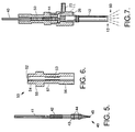
- Fig. 5 shows a cross sectional view of a needle assembly 40 used in the modular jet spray device 10 shown in Fig. 1.
- the needle assembly 40 is comprised of a relatively small cross section solid body 41 that is pointed at one end to form a needle 45.
- the body 41 has a threaded coupling 42 generally adjacent its center that is larger than the nominal diameter of the body 41.
- the threaded coupling 42 is used to mate with an internal threaded coupling 53 (Fig. 6) in the sleeve assembly 50.
- the body 41 has a sealing section 43 that comprises a relatively large diameter portion of the body 41 that has a plurality of O-rings 44 disposed in grooves formed in the sealing section 43.
- the O-rings form a needle shaft seal between the needle assembly 40 and the sleeve assembly 50 (Fig. 6).
- the O-rings 44 are designed to seal the needle assembly 40 when it is mated to the valve body 11.
- the needle assembly 40 is mated with the sleeve assembly 50, which is illustrated in Fig. 6.
- Fig. 6 shows a cross sectional view of the sleeve assembly 50 used in the modular jet spray device 10 shown in Fig. 1.
- the sleeve assembly 50 mates with and secures the needle assembly 40 and comprises a body 51 having an axial hole 52 therethrough into which the needle assembly 40 is inserted.
- the sleeve assembly 50 has an internal threaded coupling 53 disposed within the axial hole 52 that mates with the threaded coupling 42 of the needle assembly 40.
- the sleeve assembly 50 has an outer threaded coupling 54 that mates with the threaded coupling 21 of the valve body 11.
- a shoulder 55 is provided that limits insertion of the sleeve assembly 50 into the valve body 11.
- the sleeve assembly 50 also has a second outer threaded coupling 56 to which the micrometer gage 15 is secured.
- Fig. 7 shows a cross sectional internal view of a fully assembled modular jet spray device 10.
- the sleeve assembly 50 is shown threaded into the valve body 11 by means of the threaded couplings 24, 54.
- the needle 45 is shown extending into the output orifice 35 of the jet spray nozzle 12. Changing the relative position of the needle 45 in the output orifice 35 changes the amount of carbon dioxide (CO 2 ) spray 60 that emanates from the nozzle 12.
- the jet spray nozzle 10 is internally sealed by means of the seal 26 and the O-rings 44 where they mate with their corresponding surfaces and the metal to metal seals provided by the threaded couplings 21, 54, 24, 36.
- the modular jet spray device 10 provides for a much finer adjustment of spray parameters and is assembled from easily manufacturable components in modular form. No other jet spray device has the configuration options offered by this modular design.
- the design of the modular jet spray device 10 provides for rapid matching of orifice 35, nozzle 12, and needle assembly 40 combinations for optimized cleaning of submicron sized particles and molecular films.
- the modular jet spray device 10 has been built and tested using CO 2 spray as a cleaning agent and has successfully removed particulates from substrates with minimal risk. A number of tests were performed along with other non-product evaluations to investigate the performance of the modular jet spray device 10 using CO 2 spray as a cleaning agent.
- a low-temperature cofired ceramic electronics package was evaluated for CO 2 spray cleaning.
- the package had a residue of solder flux and some solder balls left from a furnace brazing process that attaches a hermetic seal ring. The residue proved quite tenacious when an attempt was made to clean the package with solvents and ultrasonic techniques.
- the modular jet spray device 10 the solder flux and solder balls were removed using an aggressive CO 2 spray in a clean dry booth (CDB) environment.
- the low-temperature cofired ceramic package was sprayed using the modular jet spray device 10 for about 30 seconds per braze joint using a model 882 nozzle (0.150 to 0.1625 inches in diameter) manufactured by the assignee of the present invention.
- the micrometer setting was 85 on the needle valve and the working distance was 1/2 inch to 3/4 inch from the braze fillet that was to be cleaned at a near normal angle. This produced a very aggressive spray plume that thermally shocked the flux and then cracked and removed it from the braze joint.
- the modular jet spray device 10 was also tested with traveling wave tubes manufactured by the assignee of the present invention in order to determine if CO 2 spray cleaning could replace Freon spray cleaning of the tubes.
- Four traveling wave tubes were cleaned with CO 2 spray using the modular jet spray device 10.
- the tubes were fabricated into completed assemblies and then evaluated during vacuum bakeout and acceptance tests. The results of these tests indicate that CO 2 spray cleaning can be used to replace Freon spray cleaning in the traveling wave tube fabrication process.
- a traveling wave tube is constructed by brazing copper clad magnetic iron washers to monel spacers in an alternating fashion.
- the resulting structure looks much like a string of beads on an abacus.
- the interior of the barrel is precision honed and cleaned with an ultrasonic probe to remove the honing debris.
- the barrel is heated up and internal components installed, producing a slight mechanical press fit upon barrel cooling.
- the internal barrel of an assembled traveling wave tube contains a helical coil and 3 boron nitride positioning rods that are coated with pyrolytic carbon. All foreign material must be removed after assembly and prior to vacuum bakeout. These tubes are evacuated and sealed at 10 -9 tort during final assembly and outgassing particles cause failure. Removal of the pyrolytic carbon or repositioning of the interior coils during the cleaning process adversely affect the performance of the traveling wave tube.
- Each traveling wave tube was sprayed externally for about 30 seconds to remove any particles and prevent any migration of particles back into the inside of the tube.
- the interior was sprayed for about 5 minutes total while rotating the tube around the CO 2 spray plume.
- the plume was oriented with about a 10 degree angle to the axis of the tube and at times a 10 degree tilt to produce a spiral cleaning action.
- a very aggressive nozzle (model 882) was used with the modular jet spray device 10 with a setting of 90 as read by the micrometer gage 15. This produced a very compact but powerful and aggressive spray that did not build up in the barrel 31 of the nozzle assembly 12 and clog it shut.
- the traveling wave tube was swapped end for end several times during cleaning and warmed up twice during cleaning. A very light film, possibly organic, frosted up on the outside of the traveling wave tube during cleaning, was easily cleaned, and did not reappear during further interior spraying.
- the modular jet spray device 10 was used to provide CO 2 spray cleaning that removed spacer balls from counter electrodes used in the traveling wave tubes. Particles are a major cause of defective traveling wave tubes, and the use of CO 2 spray cleaning with the modular jet spray device 10 is the only cleaning apparatus that allows one-step cleaning after manufacture. The results from cleaning tests showed no effect on the components or their alignment, only areas free of particulates.
Landscapes
- Engineering & Computer Science (AREA)
- Mechanical Engineering (AREA)
- Nozzles (AREA)
- Containers And Packaging Bodies Having A Special Means To Remove Contents (AREA)
Applications Claiming Priority (2)
| Application Number | Priority Date | Filing Date | Title |
|---|---|---|---|
| US08/395,124 US5611491A (en) | 1995-02-27 | 1995-02-27 | Modular CO2 jet spray device |
| US395124 | 1995-02-27 |
Publications (2)
| Publication Number | Publication Date |
|---|---|
| EP0728529A2 true EP0728529A2 (de) | 1996-08-28 |
| EP0728529A3 EP0728529A3 (de) | 1996-11-13 |
Family
ID=23561798
Family Applications (1)
| Application Number | Title | Priority Date | Filing Date |
|---|---|---|---|
| EP96100371A Withdrawn EP0728529A3 (de) | 1995-02-27 | 1996-01-11 | Modulare Zerstäubungsvorrichtung für CO2 |
Country Status (4)
| Country | Link |
|---|---|
| US (1) | US5611491A (de) |
| EP (1) | EP0728529A3 (de) |
| JP (1) | JPH08266959A (de) |
| IL (1) | IL116953A0 (de) |
Cited By (3)
| Publication number | Priority date | Publication date | Assignee | Title |
|---|---|---|---|---|
| EP2039653A3 (de) * | 2007-09-20 | 2009-05-27 | Mitsubishi Materials Corporation | Reaktor für polykristallines Silicium und Verfahren zur Herstellung von polykristallinem Silicium |
| US8038649B2 (en) * | 2007-09-18 | 2011-10-18 | Shl Group Ab | Automatic injection device with needle insertion |
| US20110259971A1 (en) * | 2007-12-20 | 2011-10-27 | Askin Steven R | Fluid injection assembly for nozzles |
Families Citing this family (21)
| Publication number | Priority date | Publication date | Assignee | Title |
|---|---|---|---|---|
| JP3158966B2 (ja) * | 1995-06-19 | 2001-04-23 | 松下電器産業株式会社 | バンプ付電子部品の製造装置および製造方法 |
| DE19621835A1 (de) * | 1996-05-31 | 1997-12-04 | Aga Ab | Expansionsdüse und Verfahren zur Erzeugung von Kohlendioxidschnee |
| US5766368A (en) * | 1997-02-14 | 1998-06-16 | Eco-Snow Systems, Inc. | Integrated circuit chip module cleaning using a carbon dioxide jet spray |
| USD403474S (en) | 1997-03-03 | 1998-12-29 | Richard R. Zito R & D Corp. | Hand held CO2 snow cleaner |
| US6442980B2 (en) * | 1997-11-26 | 2002-09-03 | Chart Inc. | Carbon dioxide dry cleaning system |
| US6216302B1 (en) * | 1997-11-26 | 2001-04-17 | Mve, Inc. | Carbon dioxide dry cleaning system |
| US5904737A (en) * | 1997-11-26 | 1999-05-18 | Mve, Inc. | Carbon dioxide dry cleaning system |
| US6296716B1 (en) * | 1999-10-01 | 2001-10-02 | Saint-Gobain Ceramics And Plastics, Inc. | Process for cleaning ceramic articles |
| US6852173B2 (en) * | 2002-04-05 | 2005-02-08 | Boc, Inc. | Liquid-assisted cryogenic cleaning |
| US20050217706A1 (en) * | 2002-04-05 | 2005-10-06 | Souvik Banerjee | Fluid assisted cryogenic cleaning |
| US7308801B1 (en) * | 2002-09-13 | 2007-12-18 | Isothermal Systems Research, Inc. | Method of operating a spray unit |
| US20090126760A1 (en) * | 2005-01-12 | 2009-05-21 | Boc, Inc. | System for cleaning a surface using crogenic aerosol and fluid reactant |
| US7389941B2 (en) * | 2005-10-13 | 2008-06-24 | Cool Clean Technologies, Inc. | Nozzle device and method for forming cryogenic composite fluid spray |
| KR100733998B1 (ko) * | 2005-12-24 | 2007-06-29 | 한국철도기술연구원 | 전기저항 시험용 분무장치 및 이에 사용되는 분무 노즐 |
| US20090107526A1 (en) * | 2007-10-31 | 2009-04-30 | Zhuge Jun | Co2 system for polymer film cleaning |
| US8833078B2 (en) | 2009-02-27 | 2014-09-16 | D2Bg Llc | Compressed gas-driven device with passive thermodynamic composition |
| US8635873B2 (en) * | 2009-02-27 | 2014-01-28 | D2Bg Llc | Compressed gas-driven device with passive thermodynamic composition |
| US8454409B2 (en) | 2009-09-10 | 2013-06-04 | Rave N.P., Inc. | CO2 nozzles |
| US9027588B2 (en) | 2011-04-28 | 2015-05-12 | Kabushiki Kaisha Toshiba | Pressure control device |
| WO2018187513A1 (en) | 2017-04-04 | 2018-10-11 | Cleanlogix Llc | Passive electrostatic co2 composite spray applicator |
| CN118613338A (zh) * | 2022-05-10 | 2024-09-06 | 杰拉尔德·亨里齐 | 孔口检查及孔口二氧化碳清洗的设备和方法 |
Family Cites Families (6)
| Publication number | Priority date | Publication date | Assignee | Title |
|---|---|---|---|---|
| US1200425A (en) * | 1913-11-01 | 1916-10-03 | John Jonathan Kermode | Burner for liquid fuel. |
| US2583659A (en) * | 1949-09-20 | 1952-01-29 | Nicholas F Martin | Vernier-type oil burner nozzle |
| US2600040A (en) * | 1950-01-13 | 1952-06-10 | John J Widmayer | Air gun for applying plaster |
| US3515354A (en) * | 1967-08-21 | 1970-06-02 | Donald R Presson | Spray nozzle |
| US4806171A (en) * | 1987-04-22 | 1989-02-21 | The Boc Group, Inc. | Apparatus and method for removing minute particles from a substrate |
| US5409418A (en) * | 1992-09-28 | 1995-04-25 | Hughes Aircraft Company | Electrostatic discharge control during jet spray |
-
1995
- 1995-02-27 US US08/395,124 patent/US5611491A/en not_active Expired - Lifetime
-
1996
- 1996-01-11 EP EP96100371A patent/EP0728529A3/de not_active Withdrawn
- 1996-01-29 IL IL11695396A patent/IL116953A0/xx unknown
- 1996-02-27 JP JP8039912A patent/JPH08266959A/ja active Pending
Cited By (8)
| Publication number | Priority date | Publication date | Assignee | Title |
|---|---|---|---|---|
| US8038649B2 (en) * | 2007-09-18 | 2011-10-18 | Shl Group Ab | Automatic injection device with needle insertion |
| EP2039653A3 (de) * | 2007-09-20 | 2009-05-27 | Mitsubishi Materials Corporation | Reaktor für polykristallines Silicium und Verfahren zur Herstellung von polykristallinem Silicium |
| US8231724B2 (en) | 2007-09-20 | 2012-07-31 | Mitsubishi Materials Corporation | Reactor for polycrystalline silicon and polycrystalline silicon production method |
| RU2470098C2 (ru) * | 2007-09-20 | 2012-12-20 | Мицубиси Матириалз Корпорейшн | Реактор для поликристаллического кремния и способ получения поликристаллического кремния |
| CN101392408B (zh) * | 2007-09-20 | 2014-03-05 | 三菱麻铁里亚尔株式会社 | 多晶硅反应炉和多晶硅的制备方法 |
| US8790429B2 (en) | 2007-09-20 | 2014-07-29 | Mitsubishi Materials Corporation | Reactor for polycrystalline silicon and polycrystalline silicon production method |
| US20110259971A1 (en) * | 2007-12-20 | 2011-10-27 | Askin Steven R | Fluid injection assembly for nozzles |
| US8568018B2 (en) * | 2007-12-20 | 2013-10-29 | Rave N.P., Inc. | Fluid injection assembly for nozzles |
Also Published As
| Publication number | Publication date |
|---|---|
| EP0728529A3 (de) | 1996-11-13 |
| IL116953A0 (en) | 1996-05-14 |
| US5611491A (en) | 1997-03-18 |
| JPH08266959A (ja) | 1996-10-15 |
Similar Documents
| Publication | Publication Date | Title |
|---|---|---|
| US5611491A (en) | Modular CO2 jet spray device | |
| US8771427B2 (en) | Method of manufacturing integrated circuit devices | |
| US12454117B2 (en) | Kinetically limited nano-scale diffusion bond structures and methods | |
| US20040005134A1 (en) | Apparatus for cleaning optical fiber connectors and fiber optic parts | |
| WO2011070154A1 (en) | A waterjet assembly comprising a structural waterjet nozzle | |
| US4989070A (en) | Modular heat sink structure | |
| TWI905120B (zh) | 小滴產生器噴嘴及其製造方法 | |
| US5563391A (en) | Orbital head laser welder | |
| US20030141784A1 (en) | Megasonic probe energy director | |
| JP3223183B2 (ja) | 半導体ディスクのための保持装置の製造方法及び該方法によって製造される保持装置 | |
| CN112233961A (zh) | 基板处理装置 | |
| JPH05175139A (ja) | セラミックスヒーター | |
| US5197653A (en) | Method of sealing two articles together with an indium preform seal | |
| RU2819011C1 (ru) | Способ пайки пиролитического нитрида бора с металлами | |
| JP2003036999A (ja) | 超電導高周波加速空胴の製造方法 | |
| CN116540370B (zh) | 光纤探针及光纤探针的制作方法 | |
| Kim et al. | Development of a 1 MHz Megasonic for a Bare Wafer Cleaning | |
| WO2025166060A1 (en) | Method and apparatus for cleaning a wafer edge and bevel | |
| Hunnell | Design, construction and initial testing of experimental test package for convective spray cooling in terrestrial gravity conditions | |
| CN120794382A (zh) | 一种无磁真空法兰连接件及制作方法 | |
| CALLIS et al. | PERFORMANCE OF THE DIII-D SYSTEM | |
| WO2024022745A1 (en) | Droplet generator nozzle | |
| Paterson et al. | Ceramic to metal brazed rectangular insulator for neutral beam accelerators | |
| Yerganian | Ceramic Element Bonding For Piezoelectric Motors | |
| JP2005241912A (ja) | 光ファイバ固定具の端面研磨加工装置 |
Legal Events
| Date | Code | Title | Description |
|---|---|---|---|
| PUAI | Public reference made under article 153(3) epc to a published international application that has entered the european phase |
Free format text: ORIGINAL CODE: 0009012 |
|
| AK | Designated contracting states |
Kind code of ref document: A2 Designated state(s): DE FR GB |
|
| PUAL | Search report despatched |
Free format text: ORIGINAL CODE: 0009013 |
|
| AK | Designated contracting states |
Kind code of ref document: A3 Designated state(s): DE FR GB |
|
| 17P | Request for examination filed |
Effective date: 19970513 |
|
| RAP1 | Party data changed (applicant data changed or rights of an application transferred) |
Owner name: HE HOLDINGS, INC. |
|
| 17Q | First examination report despatched |
Effective date: 19980514 |
|
| STAA | Information on the status of an ep patent application or granted ep patent |
Free format text: STATUS: THE APPLICATION IS DEEMED TO BE WITHDRAWN |
|
| 18D | Application deemed to be withdrawn |
Effective date: 19981125 |