EP0728631A2 - Dispositif comprenant manocontact de basse pression, capsule détonante et générateur de gaz à propergol liquide - Google Patents
Dispositif comprenant manocontact de basse pression, capsule détonante et générateur de gaz à propergol liquide Download PDFInfo
- Publication number
- EP0728631A2 EP0728631A2 EP96301157A EP96301157A EP0728631A2 EP 0728631 A2 EP0728631 A2 EP 0728631A2 EP 96301157 A EP96301157 A EP 96301157A EP 96301157 A EP96301157 A EP 96301157A EP 0728631 A2 EP0728631 A2 EP 0728631A2
- Authority
- EP
- European Patent Office
- Prior art keywords
- squib
- pressure
- hermetically sealed
- chamber
- sealed chamber
- Prior art date
- Legal status (The legal status is an assumption and is not a legal conclusion. Google has not performed a legal analysis and makes no representation as to the accuracy of the status listed.)
- Withdrawn
Links
Images



Classifications
-
- B—PERFORMING OPERATIONS; TRANSPORTING
- B60—VEHICLES IN GENERAL
- B60R—VEHICLES, VEHICLE FITTINGS, OR VEHICLE PARTS, NOT OTHERWISE PROVIDED FOR
- B60R21/00—Arrangements or fittings on vehicles for protecting or preventing injuries to occupants or pedestrians in case of accidents or other traffic risks
- B60R21/02—Occupant safety arrangements or fittings, e.g. crash pads
- B60R21/16—Inflatable occupant restraints or confinements designed to inflate upon impact or impending impact, e.g. air bags
- B60R21/26—Inflatable occupant restraints or confinements designed to inflate upon impact or impending impact, e.g. air bags characterised by the inflation fluid source or means to control inflation fluid flow
- B60R21/268—Inflatable occupant restraints or confinements designed to inflate upon impact or impending impact, e.g. air bags characterised by the inflation fluid source or means to control inflation fluid flow using instantaneous release of stored pressurised gas
- B60R21/272—Inflatable occupant restraints or confinements designed to inflate upon impact or impending impact, e.g. air bags characterised by the inflation fluid source or means to control inflation fluid flow using instantaneous release of stored pressurised gas with means for increasing the pressure of the gas just before or during liberation, e.g. hybrid inflators
-
- B—PERFORMING OPERATIONS; TRANSPORTING
- B60—VEHICLES IN GENERAL
- B60R—VEHICLES, VEHICLE FITTINGS, OR VEHICLE PARTS, NOT OTHERWISE PROVIDED FOR
- B60R21/00—Arrangements or fittings on vehicles for protecting or preventing injuries to occupants or pedestrians in case of accidents or other traffic risks
- B60R21/02—Occupant safety arrangements or fittings, e.g. crash pads
- B60R21/16—Inflatable occupant restraints or confinements designed to inflate upon impact or impending impact, e.g. air bags
- B60R21/26—Inflatable occupant restraints or confinements designed to inflate upon impact or impending impact, e.g. air bags characterised by the inflation fluid source or means to control inflation fluid flow
- B60R2021/26029—Ignitors
- B60R2021/26052—Ignitors using fluid materials
-
- B—PERFORMING OPERATIONS; TRANSPORTING
- B60—VEHICLES IN GENERAL
- B60R—VEHICLES, VEHICLE FITTINGS, OR VEHICLE PARTS, NOT OTHERWISE PROVIDED FOR
- B60R21/00—Arrangements or fittings on vehicles for protecting or preventing injuries to occupants or pedestrians in case of accidents or other traffic risks
- B60R21/02—Occupant safety arrangements or fittings, e.g. crash pads
- B60R21/16—Inflatable occupant restraints or confinements designed to inflate upon impact or impending impact, e.g. air bags
- B60R21/26—Inflatable occupant restraints or confinements designed to inflate upon impact or impending impact, e.g. air bags characterised by the inflation fluid source or means to control inflation fluid flow
- B60R21/268—Inflatable occupant restraints or confinements designed to inflate upon impact or impending impact, e.g. air bags characterised by the inflation fluid source or means to control inflation fluid flow using instantaneous release of stored pressurised gas
- B60R21/272—Inflatable occupant restraints or confinements designed to inflate upon impact or impending impact, e.g. air bags characterised by the inflation fluid source or means to control inflation fluid flow using instantaneous release of stored pressurised gas with means for increasing the pressure of the gas just before or during liberation, e.g. hybrid inflators
- B60R2021/2725—Inflatable occupant restraints or confinements designed to inflate upon impact or impending impact, e.g. air bags characterised by the inflation fluid source or means to control inflation fluid flow using instantaneous release of stored pressurised gas with means for increasing the pressure of the gas just before or during liberation, e.g. hybrid inflators using a fluid fuel gas generator
-
- B—PERFORMING OPERATIONS; TRANSPORTING
- B60—VEHICLES IN GENERAL
- B60R—VEHICLES, VEHICLE FITTINGS, OR VEHICLE PARTS, NOT OTHERWISE PROVIDED FOR
- B60R21/00—Arrangements or fittings on vehicles for protecting or preventing injuries to occupants or pedestrians in case of accidents or other traffic risks
- B60R21/02—Occupant safety arrangements or fittings, e.g. crash pads
- B60R21/16—Inflatable occupant restraints or confinements designed to inflate upon impact or impending impact, e.g. air bags
- B60R21/26—Inflatable occupant restraints or confinements designed to inflate upon impact or impending impact, e.g. air bags characterised by the inflation fluid source or means to control inflation fluid flow
- B60R21/264—Inflatable occupant restraints or confinements designed to inflate upon impact or impending impact, e.g. air bags characterised by the inflation fluid source or means to control inflation fluid flow using instantaneous generation of gas, e.g. pyrotechnic
Definitions
- This invention relates to combining the functions of an initiator, gas generator/heater and a "low pressure switch” (LPS) into a single device for convenience, termed herein an "initiator/monitor” device and having especial utility in the inflator of a vehicular stored gas inflatable air bag safety restraint system.
- a stored gas system includes a gas generator for the generation of gas and a vessel in which compressed or pressurized gas is stored to supply additional gas under pressure to inflate an inflatable air bag to protect the occupants of a vehicle upon the impact thereof with a harm producing object.
- An inflatable air bag has a folded condition for storage in a steering wheel, dashboard or other appropriate location within a vehicle in close proximity to normal occupant position.
- expansion of the inflatable bag may be effected or augmented by an inflator comprising a fluid supply in the form of a pressure vessel defining a chamber which contains a stored compressed or pressurized supply of gas.
- a pressurized stored gas supply in a pressure vessel is released upon the actuation of a gas generator, more particularly, a pyrotechnic heater, which heats and increases the pressure of the stored gas.
- a gas generator more particularly, a pyrotechnic heater
- This causes the rupture of a portion of the pressure vessel which communicates with suitable gas flow directing means leading to and allowing the gas to escape into the interior of an inflatable bag.
- the bag inflates in front of the occupant and acts as a protective cushion.
- Another object of the invention is to provide in a single device a combination LPS/initiator/gas generator for a compressed gas air bag inflator.
- the switch acts as a low pressure switch when the pressure inside the switch is set such that it forces two diaphragms together, completing an electrical circuit including the pressure monitoring resistor when there is sufficient pressure in the hybrid inflator for proper air bag inflation.
- a pressure drop in the inflator causes the diaphragms to be forced apart opening the electrical circuit through the pressure monitoring resistor.
- the bridgewire resistor inside the low pressure switch body preferably has a resistance value higher than or comparable to that of the pressure monitoring resistor and never loses continuity until it has performed as expected or operated properly, that is, functioned.
- the resistance measured by the diagnostic unit would change to 50 ohms (the resistance of the bridgewire circuit alone) and the diagnostic unit would detect that the low pressure switch had lost continuity. If the bridgewire resistor somehow became disconnected, the resistance would change to 100 ohms (the resistance of the pressure monitoring resistor alone) and the diagnostic unit would detect this also. Under normal operating conditions, both circuits would be closed and 33 ohms would be measured at all times. In the event of a vehicular collision, the diagnostic unit would apply a large current through the low pressure switch pins, causing the bridgewire resistor to heat to a predetermined level to ignite the solid material or explosive gas(es) in the initiator/ monitoring device.
- the pressure monitoring resistor could have a fuse incorporated therewith to break continuity immediately upon application of the large current so as not to interfere with the operation of the bridgewire resistor ignition.
- the gas inside the low pressure switch body expands and ruptures at least one pressure disc in the wall of the low pressure switch body, allowing the hot gas to mix with the stored gas(es) in the inflator and to ignite or expand it/them. This, in turn, builds up enough pressure to cause a diaphragm restraining the stored inflator gas to rupture, allowing that gas to vent or escape into the air bag and to inflate it.
- a liquid-fueled device incorporates a squib (pyrometer) and gas generator functions into the low pressure switch.
- a squib pyrometer
- gas generator functions into the low pressure switch.
- This embodiment is similar to that described above, but incorporates a liquid rather than a gaseous fuel, and a pyrotechnic initiator rather than a hot wire or spark-discharge system.
- the function of this embodiment of the invention as it relates to a typical hybrid inflation system, consists of two parts. First, it is designed to sense when the stored inert gas in the inflator falls below a predetermined value deemed to be unacceptable. Second, upon ignition of the squib (or pyrotechnic) initiator, the flammable mixture stored within the device ignites and causes the external wall of the device to rupture violently.
- the external wall of the liquid-fueled device is in direct contact with the inert gas storage chamber of the hybrid inflator, the hot, high pressure gases produced by combustion of the stored mixture immediately mix with the stored inert gas. In this manner, the pressure of the inert gas is raised such that a thin rupture disc used to contain the mixture ruptures, allowing the gas mixture to escape or vent into an air bag to inflate it.
- the initiator/low pressure device is physically sized such that sufficient energy is transferred to the stored inert gas to cause the pressure thereof to rise enough to cause the rupture disc to fail.
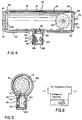
- the initiator/monitor device 24 includes a chamber 34 which is pressurized to a predetermined reference or control level.
- the chamber 34 which is hermetically sealed, is defined by two mirror symmetrical electrically conductive flexible diaphragms 36 and 38.
- Each of the diaphragms 36 and 38 may have a raised surface 40 and 42, respectively, as shown, in the central region thereof.
- a resistor 44 which may have a value of 100 ohms and serves a low pressure switch monitoring function.
- Resistor 44 is adapted to make and break contact with the diaphragm raised surfaces 40 and/or 42 as the diaphragms 36 and 38 move toward and away from each other from a predetermined spaced relation.
- the diaphragms 36 and 38 which, typically, may be made out of stainless steel or other suitable material including inconel and carbon steel, are physically positioned in parallel relation to each other.
- Each of the diaphragms 36 and 38 termed first and second diaphragms, respectively hereinafter, is attached in a symmetrical manner, as by brazing, in sealing relation to a respectively associated electrically conductive protective ring or washer 46 and 48.
- the protective rings 46 and 48 are mounted in spaced relation to each other on the opposite sides of an electrically non-conductive spacer ring or washer 50, being hermetically sealed thereto by suitable sealing means indicated at 52 and 54, respectively.
- the diaphragms 36 and 38 may be attached directly to the electrically non-conductive spacer ring 50 and backed up with the protective rings 46 and 48 or another suitable backing method.
- each of the protective rings 46 and 48 has a first side 56 and 58, respectively, and a second side 60 and 62, respectively.
- the first diaphragm 36 is attached in sealing relationship to the first side 56 of the first protective ring 46, symmetrically with respect to an aperture 64 in the ring 46.
- the second diaphragm 38 is attached in sealing relationship to the second side 62 of the second protective ring 48, symmetrically with respect to an aperture 66 in the ring 48.
- the first side 56 of the first protective ring 46 is disposed in sealing relationship with a first side 68 of the spacer ring 50.
- the second side 62 of the second protective ring 48 is disposed in sealing relationship with the second side 70 of the spacer ring 50.
- each of the pins 72 and 73 may be welded to a respectively associated one of the protective rings 46 and 48.
- the reference or control pressure level to which the chamber 34 is selected to be pressurized typically is lower by about 200-300 psi than that of the stored gas in the pressure vessel 12 which is to be monitored by the initiator/monitor device 24.
- Diffuser 28 comprises a generally cylindrical sleeve 94 that is joined at one end to the sleeve 16, at a depressed portion 96 of the surface 30 thereof in which the orifice 32 is provided, by a circumferential weld 98.
- the other end of sleeve 94 is joined to and sealed by a gas impervious closure plate 100.
- a thin metal diaphragm 102 referred to hereinafter as a third diaphragm, provides a seal for orifice 32 in the wall of sleeve 16 which defines storage chamber 14.
- a plurality of orifices 104 for dispensing inflating gas uniformly from chamber 14 into an air bag assembly (not shown).
- a diagnostic unit (not shown) supplies a large current through the pins 72 and 73, causing the bridgewire resistor 74 to ignite the gas in the chamber 34 of the initiator/monitor device 24.
- the gas in chamber 34 explodes and ruptures pressure discs 110 in the wall members 46 and 48 of the initiator/monitor device 24, allowing the hot gas to mix with the stored gas in chamber 14 of the pressure vessel 12. This heats the stored gas in vessel 12 causing a rapid pressure rise in the chamber 14.
- the diaphragm 102 ruptures allowing the heated stored gas to vent through the orifice 32 and the diffuser orifices 104 into the inflatable bag assembly.
- the diffuser diaphragm 102 and the storage chamber 14 are one or more constricting orifices 32 which throttle the flow of gas from the storage chamber 14, providing the proper fill rate to the air bag.
- the coarse screen or perforated metal sheet 106 prevents fragments of the initiator/monitor 24 and diaphragm 102 from entering the air bag assembly.
- Impingement filter 108 on the fill port and plug 18 provides further filtering by condensing thereon liquid phase particles entrained in the impinging gases.
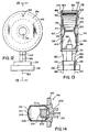
- the hybrid squib 198 serves several purposes in the fluid-filled inflator. First, it keeps the liquid fuel out of contact with the electrically energized pins 184 and 186. Second, it provides a means for long-term storage of the liquid fuel used to drive the inflation process. The physical size of the liquid fuel output can 206 is chosen by the amount of energy needed to drive the inflation process through combustion of the liquid fuel. Third, it provides both an ignition source and a means of delivering atomized fuel into the combustion chamber 144 of the device 122.
Landscapes
- Physics & Mathematics (AREA)
- Fluid Mechanics (AREA)
- Engineering & Computer Science (AREA)
- Mechanical Engineering (AREA)
- Air Bags (AREA)
Applications Claiming Priority (2)
| Application Number | Priority Date | Filing Date | Title |
|---|---|---|---|
| US392633 | 1995-02-21 | ||
| US08/392,633 US5496062A (en) | 1994-02-16 | 1995-02-21 | Liquid-fueled device to combine the functions of a low pressure switch (LPS), squib, and gas generator |
Publications (2)
| Publication Number | Publication Date |
|---|---|
| EP0728631A2 true EP0728631A2 (fr) | 1996-08-28 |
| EP0728631A3 EP0728631A3 (fr) | 1996-11-06 |
Family
ID=23551395
Family Applications (1)
| Application Number | Title | Priority Date | Filing Date |
|---|---|---|---|
| EP96301157A Withdrawn EP0728631A3 (fr) | 1995-02-21 | 1996-02-21 | Dispositif comprenant manocontact de basse pression, capsule détonante et générateur de gaz à propergol liquide |
Country Status (3)
| Country | Link |
|---|---|
| US (1) | US5496062A (fr) |
| EP (1) | EP0728631A3 (fr) |
| JP (1) | JP3028182U (fr) |
Cited By (1)
| Publication number | Priority date | Publication date | Assignee | Title |
|---|---|---|---|---|
| CN102438867A (zh) * | 2009-03-16 | 2012-05-02 | 艾尔希汽车公司 | 固体推进剂/液体型混合气体发生器 |
Families Citing this family (26)
| Publication number | Priority date | Publication date | Assignee | Title |
|---|---|---|---|---|
| US5601310A (en) * | 1995-09-19 | 1997-02-11 | Atlantic Research Corporation | Hybrid inflator and method of use |
| US6273462B1 (en) * | 1995-09-22 | 2001-08-14 | Trw Vehicle Safety Systems Inc. | Air bag inflator |
| US5659295A (en) * | 1995-12-11 | 1997-08-19 | Bendix-Atlantic Inflator Company | Sliding piston pressure sensing device |
| US5713597A (en) * | 1996-04-22 | 1998-02-03 | Trw Inc. | Method and apparatus for storing fluid under pressure |
| US5683108A (en) * | 1996-05-01 | 1997-11-04 | Trw Vehicle Safety Systems Inc. | Air bag inflator |
| US5792959A (en) * | 1996-05-06 | 1998-08-11 | Autoliv Asp, Inc. | Pressure detection method and device |
| US5787563A (en) * | 1996-05-07 | 1998-08-04 | Mst Automotive Of America Inc. | Method for assembling a compressed air bag inflator |
| US5738372A (en) * | 1996-05-15 | 1998-04-14 | Morton International, Inc. | Device for pressure relief during bonfire and tell-tale of compressed gas |
| US5736668A (en) * | 1996-05-28 | 1998-04-07 | Trw Inc. | Inflator for an inflatable vehicle occupant protection device |
| US5988069A (en) * | 1996-11-12 | 1999-11-23 | Universal Propulsion Company, Inc. | Electric initiator having a sealing material forming a ceramic to metal seal |
| US6098548A (en) * | 1997-03-05 | 2000-08-08 | Autoliv Asp, Inc. | Non-pyrotechnic initiator |
| AU9774198A (en) * | 1997-09-08 | 1999-03-29 | Paul G. Apen | Distributed charge inflator system |
| US5964479A (en) * | 1997-12-02 | 1999-10-12 | Autoliv Asp, Inc. | Acetylene-based airbag inflator |
| US5979936A (en) * | 1997-12-23 | 1999-11-09 | Autoliv Asp, Inc. | Airbag inflator |
| US6286864B1 (en) * | 1998-11-13 | 2001-09-11 | Autoliv Asp, Inc. | Ultra low cost inflator device and method of manufacturing such |
| US7188567B1 (en) | 1999-11-12 | 2007-03-13 | Zodiac Automotive Us Inc. | Gas generation system |
| WO2002051674A1 (fr) * | 2000-12-27 | 2002-07-04 | Daicel Chemical Industries, Ltd. | Gonfleur |
| JP4864251B2 (ja) | 2001-02-26 | 2012-02-01 | 株式会社ダイセル | インフレータ |
| JP2003162901A (ja) * | 2001-11-27 | 2003-06-06 | Fujitsu Display Technologies Corp | バックライトおよび液晶表示装置 |
| US7137341B2 (en) * | 2002-05-17 | 2006-11-21 | Zodiac Automotive Us Inc. | Distributed charge inflator system |
| US7162958B2 (en) * | 2002-05-17 | 2007-01-16 | Zodiac Automotive Us Inc. | Distributed charge inflator system |
| US6907827B2 (en) * | 2002-11-14 | 2005-06-21 | Special Devices, Inc. | Pyrotechnic initiator having output can with encapsulation material retention feature |
| US7520531B2 (en) * | 2006-02-28 | 2009-04-21 | Autoliv Asp, Inc. | Inflator device pressure relief |
| US20120234839A1 (en) * | 2011-03-18 | 2012-09-20 | Autoliv Asp, Inc. | Compressed gas inflator with composite overwrap |
| DE102014018007B4 (de) * | 2014-12-05 | 2025-10-30 | Zf Airbag Germany Gmbh | Hybridgasgenerator für ein Fahrzeugsicherheitssystem mit einer Öffnungsvorrichtung für einen Druckgasbehälter |
| US10124759B2 (en) | 2016-09-20 | 2018-11-13 | Autoliv Asp, Inc. | Aspirating airbag assemblies |
Family Cites Families (16)
| Publication number | Priority date | Publication date | Assignee | Title |
|---|---|---|---|---|
| US3232481A (en) * | 1963-05-23 | 1966-02-01 | Specialties Dev Corp | Apparatus for generating gaseous mixtures |
| US3606377A (en) * | 1968-11-04 | 1971-09-20 | Eaton Yale & Towne | Vehicle crash restraint system |
| US3655217A (en) * | 1969-09-18 | 1972-04-11 | Olin Corp | Safety device for vehicles |
| US3723684A (en) * | 1971-04-09 | 1973-03-27 | Itt | Pressure responsive switch with parallel contact blades bent apart by axial force applied by diaphragm |
| US3756621A (en) * | 1971-11-03 | 1973-09-04 | Allied Chem | Argon compressed gas supply |
| US3845260A (en) * | 1972-08-07 | 1974-10-29 | Allied Chem | Pressure sensing switch with movable contact diaphragm |
| DE2330194C3 (de) * | 1973-06-14 | 1978-07-06 | Bayern-Chemie Gesellschaft Fuer Flugchemische Antriebe Mbh, 8261 Aschau | Gaszuführeinheit einer Aufprallschutzvorrichtung für Kraftfahrzeuginsassen |
| US5290060A (en) * | 1992-12-14 | 1994-03-01 | Morton International, Inc. | Hybrid gas generator for air bag inflatable restraint systems |
| US5033772A (en) * | 1990-01-29 | 1991-07-23 | Allied-Signal Inc. | Hybrid inflator |
| US5016914A (en) * | 1990-02-14 | 1991-05-21 | Trw Vehicle Safety Systems Inc. | Vehicle occupant restraint system |
| US5060973A (en) * | 1990-07-23 | 1991-10-29 | General Electric Company | Liquid propellant inflator for vehicle occupant restraint apparatus |
| DE9116441U1 (de) * | 1991-03-26 | 1992-11-12 | Unimed Egon Struck Entwicklungs GmbH, 6750 Kaiserslautern | Druckschalter für Airbags und allgemeine Anwendungen mit integrierter Elektronik |
| US5225643A (en) * | 1992-03-17 | 1993-07-06 | Morton International, Inc. | Differential pressure switch for stored gas pressure vessel |
| US5296659A (en) * | 1993-01-19 | 1994-03-22 | Viz Manufacturing Company, Inc. | Differential pressure monitoring device |
| DE4301631A1 (de) * | 1993-01-22 | 1994-07-28 | Audi Ag | Gasdruckbehälter zum Aufblasen eines dem Insassenschutz in einem Kraftfahrzeug dienenden Gassackes |
| US5429387A (en) * | 1994-02-16 | 1995-07-04 | Morton International, Inc. | Low pressure switch/initiator/gas generator |
-
1995
- 1995-02-21 US US08/392,633 patent/US5496062A/en not_active Expired - Fee Related
-
1996
- 1996-02-20 JP JP1996000775U patent/JP3028182U/ja not_active Expired - Lifetime
- 1996-02-21 EP EP96301157A patent/EP0728631A3/fr not_active Withdrawn
Cited By (2)
| Publication number | Priority date | Publication date | Assignee | Title |
|---|---|---|---|---|
| CN102438867A (zh) * | 2009-03-16 | 2012-05-02 | 艾尔希汽车公司 | 固体推进剂/液体型混合气体发生器 |
| CN102438867B (zh) * | 2009-03-16 | 2016-01-20 | 艾尔希汽车公司 | 固体推进剂/液体型混合气体发生器 |
Also Published As
| Publication number | Publication date |
|---|---|
| US5496062A (en) | 1996-03-05 |
| EP0728631A3 (fr) | 1996-11-06 |
| JP3028182U (ja) | 1996-08-30 |
Similar Documents
| Publication | Publication Date | Title |
|---|---|---|
| US5496062A (en) | Liquid-fueled device to combine the functions of a low pressure switch (LPS), squib, and gas generator | |
| US6019389A (en) | Air bag inflator | |
| US5344186A (en) | Inflator assembly | |
| US5364127A (en) | Inflator assembly | |
| US5429387A (en) | Low pressure switch/initiator/gas generator | |
| US5078422A (en) | Gas inflator apparatus | |
| US5558367A (en) | Dual stage augmented inflator for an air bag | |
| US5356176A (en) | Vehicle occupant restraint apparatus | |
| US5487559A (en) | Air bag inflator with pressure sensor | |
| US6206414B1 (en) | Air bag inflator including plural burst disks | |
| CN101883700B (zh) | 气体发生器和用于影响气体发生器中气流的方法 | |
| US5821446A (en) | Inflator for an inflatable vehicle occupant protection device | |
| US5570904A (en) | Air bag inflator with movable container | |
| US5738372A (en) | Device for pressure relief during bonfire and tell-tale of compressed gas | |
| US5590906A (en) | Vehicle occupant restraint inflator | |
| US6273462B1 (en) | Air bag inflator | |
| US5226667A (en) | Percussion igniter assembly | |
| US5460406A (en) | Inflator assembly | |
| WO1998008715A1 (fr) | Appareil hybride pour gonfler des coussins pneumatiques de securite | |
| JP3307390B2 (ja) | 電熱によって膨張する拘束システム | |
| US5213362A (en) | Stab igniter assembly | |
| US5736668A (en) | Inflator for an inflatable vehicle occupant protection device | |
| US3837671A (en) | Inflating means for inflatable vehicle restraint systems | |
| US5429386A (en) | Auto ignition device for an air bag inflator | |
| US6572143B2 (en) | Air bag gas inflator |
Legal Events
| Date | Code | Title | Description |
|---|---|---|---|
| PUAI | Public reference made under article 153(3) epc to a published international application that has entered the european phase |
Free format text: ORIGINAL CODE: 0009012 |
|
| AK | Designated contracting states |
Kind code of ref document: A2 Designated state(s): DE FR GB IT |
|
| PUAL | Search report despatched |
Free format text: ORIGINAL CODE: 0009013 |
|
| AK | Designated contracting states |
Kind code of ref document: A3 Designated state(s): DE FR GB IT |
|
| STAA | Information on the status of an ep patent application or granted ep patent |
Free format text: STATUS: THE APPLICATION IS DEEMED TO BE WITHDRAWN |
|
| 18D | Application deemed to be withdrawn |
Effective date: 19970507 |