EP0728694A2 - Machine de chargement, en particulier pour dispositif de séchage de feuilles - Google Patents
Machine de chargement, en particulier pour dispositif de séchage de feuilles Download PDFInfo
- Publication number
- EP0728694A2 EP0728694A2 EP95119524A EP95119524A EP0728694A2 EP 0728694 A2 EP0728694 A2 EP 0728694A2 EP 95119524 A EP95119524 A EP 95119524A EP 95119524 A EP95119524 A EP 95119524A EP 0728694 A2 EP0728694 A2 EP 0728694A2
- Authority
- EP
- European Patent Office
- Prior art keywords
- sheets
- loading machine
- chains
- roller
- chain
- Prior art date
- Legal status (The legal status is an assumption and is not a legal conclusion. Google has not performed a legal analysis and makes no representation as to the accuracy of the status listed.)
- Withdrawn
Links
Images

Classifications
-
- F—MECHANICAL ENGINEERING; LIGHTING; HEATING; WEAPONS; BLASTING
- F26—DRYING
- F26B—DRYING SOLID MATERIALS OR OBJECTS BY REMOVING LIQUID THEREFROM
- F26B15/00—Machines or apparatus for drying objects with progressive movement; Machines or apparatus with progressive movement for drying batches of material in compact form
- F26B15/02—Machines or apparatus for drying objects with progressive movement; Machines or apparatus with progressive movement for drying batches of material in compact form with movement in the whole or part of a circle
- F26B15/08—Machines or apparatus for drying objects with progressive movement; Machines or apparatus with progressive movement for drying batches of material in compact form with movement in the whole or part of a circle in a vertical plane
- F26B15/085—Machines or apparatus for drying objects with progressive movement; Machines or apparatus with progressive movement for drying batches of material in compact form with movement in the whole or part of a circle in a vertical plane with endless clamp or tray conveyor, e.g. wicket conveyor
-
- B—PERFORMING OPERATIONS; TRANSPORTING
- B41—PRINTING; LINING MACHINES; TYPEWRITERS; STAMPS
- B41F—PRINTING MACHINES OR PRESSES
- B41F23/00—Devices for treating the surfaces of sheets, webs, or other articles in connection with printing
- B41F23/04—Devices for treating the surfaces of sheets, webs, or other articles in connection with printing by heat drying, by cooling, by applying powders
- B41F23/044—Drying sheets, e.g. between two printing stations
- B41F23/0443—Drying sheets, e.g. between two printing stations after printing
- B41F23/0446—Wicket conveyors
-
- B—PERFORMING OPERATIONS; TRANSPORTING
- B65—CONVEYING; PACKING; STORING; HANDLING THIN OR FILAMENTARY MATERIAL
- B65H—HANDLING THIN OR FILAMENTARY MATERIAL, e.g. SHEETS, WEBS, CABLES
- B65H29/00—Delivering or advancing articles from machines; Advancing articles to or into piles
Definitions
- the invention relates to a loading machine, in particular for drying systems for coated sheets or metal sheets, with chain circulating conveyors with two spaced roller chains, the links of which are each connected by brackets bridging the roller chain spacing, which are inclined upward from the chains and which in the infeed area of end deflection gears form wedge-shaped opening chambers for the essentially horizontal insertion of the sheets or metal sheets.
- Such loading machines by means of which the coated sheets or sheets arriving one after the other on horizontal conveyors can be inserted individually into the chambers between two brackets, so that they can be dried in a drying or baking plant without damaging the coated surface, have hitherto been basically so removed that behind the deflection gears, the roller chains rise obliquely on a straight path and then pass over further deflection rollers into the horizontal path within the drying system.
- brackets fanned out in a wedge-shaped manner in the deflecting area thereby get directly at the exit of the roller chains from the deflection gears into the intended inclined position relative to the roller chains, in which all brackets run parallel to one another, with the result that the brackets move from their open inclined position in a very short transition section be pivoted to each other in this parallel position.
- This causes the stirrups to vibrate and often the sheets or sheets lying on such a stirrup are flung out and strike the preceding stirrup, which can repeatedly damage the coated surface.
- the invention is therefore based on the object of designing such a loading machine in such a way that damage to the surfaces of the coated sheets or sheets can be reliably avoided even at high conveying speeds.
- roller chains are guided on an upwardly convex, in particular parabolic, path following the deflection gears.
- roller chains horizontally guided in the drying system in a manner known per se by means of spaced outer rollers running on U-rails between the inlet and the horizontal section by means of rollers in each chain link on steel cheeks provided with curved upper edges are led.
- This individual guidance of each chain link on its own roll enables the desired parabolic run-in curve to be achieved much more precisely than if only the usual normal guidance were provided by means of the outer rollers spaced apart by several chain links.
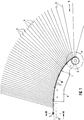
- the loading machine shown in Fig. 1 shows the inlet section of a chain conveyor with two spaced conveyor chains, of which only the conveyor chain 1 can be seen, while the other in the drawing direction parallel to the plane of Fig. 1 is to be thought of at a distance behind.
- the conveyor chains 1 are connected to each other by two mutually opposite individual chain links 2 connecting brackets 3, which form chambers 4 between each other for receiving a single coated sheet or a coated metal sheet, which is transported in a drying system adjoining the loading machine on the left in FIG. 1 should be there so that soft or moist coating can still be cured before the sheets or metal sheets with finished surface coating are removed from the other end of the drying system and the chain conveyor with the hangers hanging down is conveyed back to the right in the area of the loading machine shown in FIG.
- coated sheets or metal sheets which are not shown in the drawings, are preferably inserted by a horizontal conveyor in the direction of arrow 5 in FIG. 1 into the brackets 3, which are fanned out in a wedge shape in the inlet area of end-side deflection gears 6, and then stand up and otherwise with the edge on the circulation chains transported lying on the inclined brackets.
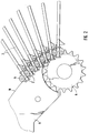
- roller chains While in the horizontal section within the drying system, i.e. in the area of section III-III and further to the left in FIG. 1, the roller chains are guided on U-shaped rails 8 by means of outer rollers 7 spaced apart by several individual chain links 2, the roller chains run in Area of the loading machine directly from the outlet from the deflection gear 6 with the help of rollers 9 assigned to each individual chain link 2 on the convexly curved upper edge 10 of steel cheeks 11, the course of the upper edge 10 preferably being parabolically curved.
- stirrups 43 do not suddenly come into their parallel position after the insertion of the sheets or metal sheets when they leave the deflection rollers, which they have at the outlet of the loading machine as well as during further transport through the drying system, but they gradually become closed by closing the wedge angle between them End position pivoted so that the sudden folding with the risk of bumping the sheets or metal sheets against the leading bracket is reliably prevented.
- Fig. 4 it can be seen how the final inclination of the bracket in the horizontal sections of the roller chains at angles of about 75 ° to the horizontal is predetermined by insertion recesses 12 and 13 of each individual chain link 2. The resulting position of the bracket is indicated by the dash-dotted line 14.
Landscapes
- Engineering & Computer Science (AREA)
- Mechanical Engineering (AREA)
- General Engineering & Computer Science (AREA)
- Drying Of Solid Materials (AREA)
Applications Claiming Priority (2)
| Application Number | Priority Date | Filing Date | Title |
|---|---|---|---|
| DE19506105A DE19506105C1 (de) | 1995-02-22 | 1995-02-22 | Belademaschine für eine Bogentrocknungsanlage |
| DE19506105 | 1995-02-22 |
Publications (2)
| Publication Number | Publication Date |
|---|---|
| EP0728694A2 true EP0728694A2 (fr) | 1996-08-28 |
| EP0728694A3 EP0728694A3 (fr) | 1997-07-09 |
Family
ID=7754722
Family Applications (1)
| Application Number | Title | Priority Date | Filing Date |
|---|---|---|---|
| EP95119524A Withdrawn EP0728694A3 (fr) | 1995-02-22 | 1995-12-12 | Machine de chargement, en particulier pour dispositif de séchage de feuilles |
Country Status (3)
| Country | Link |
|---|---|
| US (1) | US5653330A (fr) |
| EP (1) | EP0728694A3 (fr) |
| DE (1) | DE19506105C1 (fr) |
Families Citing this family (7)
| Publication number | Priority date | Publication date | Assignee | Title |
|---|---|---|---|---|
| US6884016B2 (en) * | 2002-11-04 | 2005-04-26 | Kimberly-Clark Worldwide, Inc. | Positioning system for an automatic accumulation system |
| US6918485B2 (en) | 2002-11-04 | 2005-07-19 | Kimberly-Clark Worldwide, Inc. | Orientation detection and control system |
| US6877294B2 (en) * | 2002-11-04 | 2005-04-12 | Kimberly-Clark Worldwide, Inc. | Automatic repacking and accumulation system |
| US6823981B2 (en) * | 2002-11-04 | 2004-11-30 | Kimberly-Clark Worldwide, Inc. | Conveyor system for an automatic accumulation system |
| US7108155B2 (en) * | 2002-11-04 | 2006-09-19 | Kimberly-Clark Worldwide, Inc. | Metering drum for an automatic accumulation system |
| US7159375B2 (en) * | 2003-10-08 | 2007-01-09 | Kimberly-Clark Worldwide, Inc. | Multi-product accumulating and packing system |
| JP2012048095A (ja) | 2010-08-30 | 2012-03-08 | Seiko Epson Corp | 仕分装置 |
Family Cites Families (11)
| Publication number | Priority date | Publication date | Assignee | Title |
|---|---|---|---|---|
| DE557770C (de) * | 1931-05-01 | 1932-08-27 | Benno Schilde Maschb Akt Ges | Trockenapparat fuer flaechiges Gut, insbesondere Pappen |
| US2186566A (en) * | 1937-12-09 | 1940-01-09 | Caspers Tin Plate Company | Conveyer structure for ovens |
| US2281938A (en) * | 1940-03-04 | 1942-05-05 | Chain Belt Co | Rigid-back chain |
| CH276425A (de) * | 1949-10-12 | 1951-07-15 | Fischer Ag Georg | Einrichtung zum Behandeln von Metallteilen. |
| US2668366A (en) * | 1949-11-12 | 1954-02-09 | Young Brothers Company | Heat processing apparatus |
| US3192648A (en) * | 1961-09-22 | 1965-07-06 | Moffitt Co Roy M | Sheet dryer of conveyor-wicket type with suction wickets |
| US3276569A (en) * | 1964-08-17 | 1966-10-04 | Moffitt Co Roy M | Sheet handling mechanism |
| US3370690A (en) * | 1965-10-21 | 1968-02-27 | Moffitt Co Roy M | Sheet handler-stripper |
| GB8827276D0 (en) * | 1988-11-22 | 1988-12-29 | Glaxo Group Ltd | Apparatus |
| JPH0472210A (ja) * | 1990-07-11 | 1992-03-06 | Sanei Seisakusho:Kk | コンベア |
| DE4133841A1 (de) * | 1991-10-12 | 1993-04-15 | Mueller Thomas Gmbh | Trocknungsvorrichtung |
-
1995
- 1995-02-22 DE DE19506105A patent/DE19506105C1/de not_active Expired - Lifetime
- 1995-12-12 EP EP95119524A patent/EP0728694A3/fr not_active Withdrawn
-
1996
- 1996-02-16 US US08/602,647 patent/US5653330A/en not_active Expired - Fee Related
Also Published As
| Publication number | Publication date |
|---|---|
| DE19506105C1 (de) | 1996-03-28 |
| EP0728694A3 (fr) | 1997-07-09 |
| US5653330A (en) | 1997-08-05 |
Similar Documents
| Publication | Publication Date | Title |
|---|---|---|
| DE1815317B2 (de) | Foerderanordnung fuer den transport von filterstaeben, zigaretten oder anderen stabfoermigen artikeln der tabakverarbeitenden industrie | |
| AT396908B (de) | Vorrichtung zum verarbeiten von druckprodukten | |
| DE69611740T2 (de) | Vorrichtung zum Sortieren von Produkten | |
| EP0771754B1 (fr) | Dispositif pour assembler des produits plats | |
| WO2000053984A1 (fr) | Procede de sechage de plaques de bois de placage et dispositif de sechage associe | |
| EP1559663A1 (fr) | Procédé et convoyeur destiné au transport d'objets munis d'un col | |
| DE2858724C2 (fr) | ||
| CH677100A5 (fr) | ||
| EP0728694A2 (fr) | Machine de chargement, en particulier pour dispositif de séchage de feuilles | |
| DE3119016C2 (fr) | ||
| DE1951598C3 (de) | Auswelchspur für eine Arbeitsvorrichtung enthaltende Fertigungsstraßen | |
| DE60202002T2 (de) | Verfahren und vorrichtung zum einwickeln von druckerzeugnissen | |
| EP1072546B1 (fr) | Convoyeur pour assembler et traiter des produits imprimés | |
| EP4323292A1 (fr) | Station de chargement pour un convoyeur aérien comprenant des poches de transport pour des marchandises à convoyer | |
| DE1931208C3 (de) | Vorrichtung zum Fördern und Ablegen von Bögen aus Papier und anderem blattförmigen Material in Stapeln | |
| EP0990535B1 (fr) | Méhode pour fabriquer des produits d'imprimerie par insertion d'au moins un produit constituant dans un produit principal et dispositif pour mettre en oeuvre la méthode | |
| DE3908347C2 (fr) | ||
| EP0805025B1 (fr) | Dispositif convoyeur des produits imprimés entre des groupes imprimants | |
| DE102023113439A1 (de) | Sackaufstecksystem und Verfahren zum Betreiben | |
| EP0252461A1 (fr) | Dispositif de modification d'un flux de bouteilles à plusieurs rangs en un flux de bouteilles à un seul rang | |
| DE2853114C2 (de) | Vorrichtung zum Überführen von Packungen von einer Produktionsmaschine zu einer Weiterverarbeitungsmaschine | |
| DE69504985T2 (de) | Trocknungsvorrichtung mit verbesserter führung für geschältes holzfunier | |
| EP1254855B1 (fr) | Dispositif pour désassembler une pile d'objets plats et flexibles | |
| EP1584591B1 (fr) | Dispositif de pliage avec partie supérieure ouvrable | |
| DE4409152C2 (de) | Schwenkübergabe an Bandförderern |
Legal Events
| Date | Code | Title | Description |
|---|---|---|---|
| PUAI | Public reference made under article 153(3) epc to a published international application that has entered the european phase |
Free format text: ORIGINAL CODE: 0009012 |
|
| AK | Designated contracting states |
Kind code of ref document: A2 Designated state(s): ES FR GB IT |
|
| PUAL | Search report despatched |
Free format text: ORIGINAL CODE: 0009013 |
|
| RHK1 | Main classification (correction) |
Ipc: F26B 15/08 |
|
| AK | Designated contracting states |
Kind code of ref document: A3 Designated state(s): ES FR GB IT |
|
| STAA | Information on the status of an ep patent application or granted ep patent |
Free format text: STATUS: THE APPLICATION IS DEEMED TO BE WITHDRAWN |
|
| 18D | Application deemed to be withdrawn |
Effective date: 19980110 |