EP0729005A1 - Dispositif de mesure avec 6 degrés de liberté - Google Patents
Dispositif de mesure avec 6 degrés de liberté Download PDFInfo
- Publication number
- EP0729005A1 EP0729005A1 EP95102540A EP95102540A EP0729005A1 EP 0729005 A1 EP0729005 A1 EP 0729005A1 EP 95102540 A EP95102540 A EP 95102540A EP 95102540 A EP95102540 A EP 95102540A EP 0729005 A1 EP0729005 A1 EP 0729005A1
- Authority
- EP
- European Patent Office
- Prior art keywords
- measuring
- measuring device
- carrier
- rotation
- slide
- Prior art date
- Legal status (The legal status is an assumption and is not a legal conclusion. Google has not performed a legal analysis and makes no representation as to the accuracy of the status listed.)
- Granted
Links
- 238000010168 coupling process Methods 0.000 claims description 10
- 230000008878 coupling Effects 0.000 claims description 8
- 238000005859 coupling reaction Methods 0.000 claims description 8
- 238000000034 method Methods 0.000 claims description 5
- 238000006073 displacement reaction Methods 0.000 claims description 4
- 238000004519 manufacturing process Methods 0.000 claims description 3
- 239000000463 material Substances 0.000 claims description 2
- 238000005259 measurement Methods 0.000 abstract description 29
- 238000012360 testing method Methods 0.000 description 23
- 238000011156 evaluation Methods 0.000 description 7
- 239000000523 sample Substances 0.000 description 4
- 230000003068 static effect Effects 0.000 description 3
- 230000001419 dependent effect Effects 0.000 description 2
- 238000010586 diagram Methods 0.000 description 2
- 238000010972 statistical evaluation Methods 0.000 description 2
- 238000010998 test method Methods 0.000 description 2
- 238000004364 calculation method Methods 0.000 description 1
- 238000005520 cutting process Methods 0.000 description 1
- 230000002950 deficient Effects 0.000 description 1
- 230000000694 effects Effects 0.000 description 1
- 238000003754 machining Methods 0.000 description 1
- 239000011159 matrix material Substances 0.000 description 1
- 230000003252 repetitive effect Effects 0.000 description 1
- 230000000717 retained effect Effects 0.000 description 1
Images


Classifications
-
- G—PHYSICS
- G01—MEASURING; TESTING
- G01B—MEASURING LENGTH, THICKNESS OR SIMILAR LINEAR DIMENSIONS; MEASURING ANGLES; MEASURING AREAS; MEASURING IRREGULARITIES OF SURFACES OR CONTOURS
- G01B5/00—Measuring arrangements characterised by the use of mechanical techniques
- G01B5/0002—Arrangements for supporting, fixing or guiding the measuring instrument or the object to be measured
-
- G—PHYSICS
- G01—MEASURING; TESTING
- G01B—MEASURING LENGTH, THICKNESS OR SIMILAR LINEAR DIMENSIONS; MEASURING ANGLES; MEASURING AREAS; MEASURING IRREGULARITIES OF SURFACES OR CONTOURS
- G01B21/00—Measuring arrangements or details thereof, where the measuring technique is not covered by the other groups of this subclass, unspecified or not relevant
- G01B21/02—Measuring arrangements or details thereof, where the measuring technique is not covered by the other groups of this subclass, unspecified or not relevant for measuring length, width, or thickness
- G01B21/04—Measuring arrangements or details thereof, where the measuring technique is not covered by the other groups of this subclass, unspecified or not relevant for measuring length, width, or thickness by measuring coordinates of points
- G01B21/042—Calibration or calibration artifacts
Definitions
- the invention relates to a measuring device for checking the geometric and dynamic accuracy of two machine parts moving relative to one another.
- Machine tools are subject to errors that cause dimensional, shape and position errors on the workpiece.
- the circular shape test is about measuring these circular shape deviations and evaluating the result in order to draw conclusions about the quality of the NC machine.
- US Pat. No. 4,435,905 describes a device for carrying out the circular shape test, which consists of a rod, at the ends of which balls are attached, which are each supported in an abutment.
- the two abutments are attached to the NC machine in such a way that their positions correspond to the positions of tools and workpieces.
- the rod consists of two parts, which are connected to one another in a longitudinally displaceable manner, so that the rod length is variable. The displacement of the two parts to each other is recorded by an integrated length measuring system. If a rod end is moved on a circular path around the other end, the measured values correspond to the circular shape deviations.
- the measuring device consists of an inertially fixed base body, on which an arm is rotatably mounted, which in its end region has a radial guide for a probe element detachably connected to a machine part to be tested.
- a length measuring device which cooperates with it and is arranged radially to the axis of rotation of the arm, is attached to the arm.
- a further length measuring device is provided at the end region of the arm parallel to the axis of rotation of the arm for measuring the axial displacement of the contact element.
- the length measuring device arranged radially to the axis of rotation of the arm is a probe with a very small measuring range, so that only the deviations from a predetermined circular path movement can be measured.
- the object of the invention is to provide a measuring device with which the geometric and dynamic accuracy of machines can be detected with little effort, and which is versatile.
- the measuring device is designed in a particularly advantageous manner.
- the measuring device is universal for measurements of circular movements, but also of linear movements is suitable within the entire travel path of the machine parts moving relative to one another. All movements involve simultaneous measurement of linear and rotary movements, so that the measuring device is also suitable for testing robot movements to record all axis movements.
- the universal applicability of the measuring device it is relatively simple and robust, since it consists of standard measuring systems.
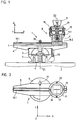
- a measuring device 1 is shown in section attached to a carriage 2 of a machine tool.
- the measuring device 1 consists of a base body 3, which is used for attachment to the carriage 2 and is the carrier of an angle measuring device 4.
- the base body 3 has a precise and play-free air bearing 5 for the rotatable mounting of a component 6 about a predetermined axis of rotation D1.
- the rotation of the component 6 relative to the base body 3 is measured by means of the angle measuring device 4, preferably an incremental rotary pulse generator.
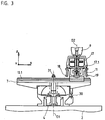
- a length measuring device 10 is provided parallel to the linear guide 7.
- This length measuring device 10 consists of a material measure 10.1 which is arranged in the form of an incremental scale along the linear guide 7 and has a length which corresponds at least approximately to the possible travel path of the machine parts 2, 9 which are moved relative to one another.
- the scale 10.1 is attached directly to a surface of the linear guide 7.
- the incremental division of the scale 10.1 is scanned by a scanning unit 10.2 known per se to form position-dependent electrical signals.
- the scanning unit 10.2 is fixedly attached to a measuring slide 11 of the measuring element 8.
- this mounting consists of a total of one linear guide 13 and three rotary bearings 14, 15, 16 about three axes of rotation D2, D3, D4.
- a carrier 17 is provided which can be moved relative to the measuring slide 11 via the above-mentioned bearings 13 to 16.
- the linear guide 13 is formed from two bolts 13.1 and 13.2 fastened to the measuring slide 11, with which two corresponding bushes 13.3 and 13.4 interact, which thus cause a longitudinal movement between the measuring slide 11 and the carrier 17 along the axis of rotation D2 in the Z direction enable.
- This longitudinal movement in the Z direction is measured by at least one further length measuring device 18 to 21.
- this length measurement is carried out by means of several probes 18 to 21 which are fastened in the carrier 17 and whose probe bolts 18.1 to 21.1 rest on a surface 11.1 of the measuring slide 11 provided at right angles to the axis of rotation D1.
- the measurement of the angle of rotation about the axis of rotation D2 is measured by an angle measuring device 22, the scanning unit of which is connected to the carrier 17, that is to say the spindle 9, and the graduated disk of which is connected to the measuring slide 11.
- a further rotary movement of the carrier 17 relative to the measuring slide 11 is possible about the axis of rotation D3 via the rotary bearing 15.
- Another rotary bearing 16 enables the rotary movement of the carrier 17 relative to the measuring slide 11 about the axis of rotation D4.
- the rotary movements about the axes of rotation D3 and D4 are measured by the four spatially arranged buttons 18 to 21 by evaluating the length difference of two symmetrically opposite buttons 18, 20 and 19, 21.
- these rotary movements can also be measured directly by means of angle measuring devices attached to the individual rotary axes D3 and D4.
- the gimbal shown is particularly advantageous. This mounting ensures that the three mutually perpendicular axes of rotation D2, D3 and D4 intersect at a common pivot point.
- the bearing could also consist of a ball, which is rotatably mounted in a ball socket.
- a flat surface 17.1 can also be on the carrier 17 and the buttons 18 to 21 on the measuring slide 11.
- the scanning head of this length measuring device would be attached to the measuring slide 11 and the scale to the carrier 17.
- the scanning head can also be attached to the carrier 17, but this would have the effect that electrical lines from the measuring slide 11 and from the carrier 17 have to be led to an evaluation unit.
- the bolts 13.1 and 13.2 of the measuring carriage 11 form with the bushes 13.3 and 13.4, which are fastened to the carrier 17, a releasable coupling between the measuring carriage 11 and the carrier 17.
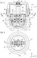
- This releasable coupling enables automated coupling, which is shown in FIG. If a machine tool is to be checked, the carrier 17 is automatically removed from a tool magazine, for example, and fastened to the spindle 9. So that a predetermined positional relationship during this movement between the universal joint 14, 15, 16, and the carrier 17 is retained until the bushings 13.3. and 13.4 are positioned in the associated bolts 13.1 and 13.2, the sockets 13.3, 13.4 are fixed by means of two controllable electromagnets 23, 24.
- the fixation takes place by the electromagnets 23, 24 extending two fixing elements 25, 26 in the direction of the bushes 13.3, 13.4 and interacting with them until the operating position shown in FIG. 4 is reached.
- the electromagnets 23, 24 are switched off, as a result of which the fixing elements 25, 26 are withdrawn by spring force and thus the operative connection with the sockets 13.3, 13.4 is released and free movement between the carrier 17 and the measuring slide 11 is made possible.
- the base body 3 with the linear guide 7 and the length measuring device 10 is also positioned in a numerically controlled manner by a pallet changer on the slide 2 of the machine tool.
- these two parts are clamped by means of a fixing element 30.
- Another fixing element 31 is provided for clamping between the component 6 and the measuring slide 11. Both fixing elements 30, 31 are controlled, for example, via an electromagnet like the fixing elements 25, 26 according to FIG. 4.
- sensors for example contactlessly operating sensors, are arranged in order to report the end positions reached after the successful coupling process to an evaluation device 27 and only to let the measuring program run automatically when the coupling is successful.
- the evaluation device 27 is shown in addition to the section of the measuring device according to the invention according to Figure 1, the evaluation device 27 is shown.
- the position measurement values P18 to P21 of the four buttons 18 to 21 are fed to a counter unit 27.1 of the evaluation device 27 and the tilt angles about the two axes of rotation D3 and D4 are determined therefrom.
- the position measurement values P4, P22 of the two angle measuring devices 4 and 22 are fed to a further counter unit 27.2 and the rotary movements about the two axes of rotation D1 and D2 are determined therefrom.
- a further counter unit 27.3 is provided for evaluating the position measurement values P10 of the length measuring device 10.
- the static and dynamic positional deviations are determined from all measurement results using evaluation software 27.4.
- the evaluation unit 27 also controls the fixing elements 30, 31 by means of separate lines P30, P31.
- a check of the geometric accuracy of a CNC machine can be carried out repeatedly not only during the initial start-up but also by the user himself after defined periods of time in order to realize controlled manufacturing processes with increasingly narrow tolerance limits.
- the simultaneous measurement of lengths and angles enables the clear establishment of an error matrix for software compensation of static and dynamic deviation parameters.
- the measurements can be carried out with little expenditure of time and personnel. Repetitive measurements are carried out with a small amount of measuring equipment using fixed measurement programs.
- the measuring device 1 has six degrees of freedom, four rotary (about the axes of rotation D1, D2, D3, D4) and two translational (X and Z directions) joints allow the recording of individual deviations independently of one another.
- a 2D evaluation can be carried out in polar coordinates.
- the yaw angle can be determined during a linear movement along the guide 7.
- the yaw angle results from the difference value of the position measurement values P4 and P22 of the angle measuring devices 4 and 22.
- the behavior of additional axes can be detected with the angle measuring device 22, which is particularly advantageous in the case of robots or also in the case of controlled rotatable spindles of machine tools.
- the length measuring device 10 eliminates any restriction due to small stylus strokes, so that a rapid variation of the circle diameter during the circular shape test and also other trajectory curves such as rectangles and polygons can be examined.
- the angle measuring devices 4, 22 a real angle measurement is possible and no calculation of the angular position from the feed rate and time.
- the length measuring devices 10, 18 to 21 and the angle measuring devices 4, 22 are preferably photoelectric incremental systems, but they can also work according to other physical principles such as capacitive or magnetic. Interferometers are also suitable as length measuring devices 10, 18 to 21.
- the evaluation software 27.4 and the counter units 27.1, 27.2, 27.3 can be installed on a measuring PC or a CNC control.
- the evaluation software 27.4 can also contain the possible measurement sequences for testing a CNC control.
- a test program for an automated quick acceptance of a CNC-controlled machine tool for the XY plane can contain the following measuring runs.
- FIG 8 some of the possible dynamic test methods for CNC machines are listed and the measurement diagrams are shown.
- the measurement diagrams can be displayed on the CNC control screen for control purposes and, if necessary, printed out using a printer.
Landscapes
- Physics & Mathematics (AREA)
- General Physics & Mathematics (AREA)
- A Measuring Device Byusing Mechanical Method (AREA)
- Machine Tool Sensing Apparatuses (AREA)
- Length Measuring Devices With Unspecified Measuring Means (AREA)
- Length Measuring Devices By Optical Means (AREA)
Priority Applications (5)
| Application Number | Priority Date | Filing Date | Title |
|---|---|---|---|
| DE59503072T DE59503072D1 (de) | 1995-02-23 | 1995-02-23 | Messvorrichtung zur Kontrolle der geometrischen und dynamischen Genauigkeit von NC-Werkzeugmaschinen und Industrierobotern |
| EP95102540A EP0729005B1 (fr) | 1995-02-23 | 1995-02-23 | Dispositif de mesure pour la vérification de la précision géométrique et dynamique des machines-outil NC et des robots industriels |
| AT95102540T ATE169395T1 (de) | 1995-02-23 | 1995-02-23 | Messvorrichtung zur kontrolle der geometrischen und dynamischen genauigkeit von nc- werkzeugmaschinen und industrierobotern |
| JP8032338A JP2831610B2 (ja) | 1995-02-23 | 1996-02-20 | 測定装置 |
| US08/606,446 US5767380A (en) | 1995-02-23 | 1996-02-23 | Measuring arrangement and method for checking the geometric and dynamic accuracy of two machine elements displaceable with respect to one another |
Applications Claiming Priority (1)
| Application Number | Priority Date | Filing Date | Title |
|---|---|---|---|
| EP95102540A EP0729005B1 (fr) | 1995-02-23 | 1995-02-23 | Dispositif de mesure pour la vérification de la précision géométrique et dynamique des machines-outil NC et des robots industriels |
Publications (2)
| Publication Number | Publication Date |
|---|---|
| EP0729005A1 true EP0729005A1 (fr) | 1996-08-28 |
| EP0729005B1 EP0729005B1 (fr) | 1998-08-05 |
Family
ID=8219005
Family Applications (1)
| Application Number | Title | Priority Date | Filing Date |
|---|---|---|---|
| EP95102540A Expired - Lifetime EP0729005B1 (fr) | 1995-02-23 | 1995-02-23 | Dispositif de mesure pour la vérification de la précision géométrique et dynamique des machines-outil NC et des robots industriels |
Country Status (5)
| Country | Link |
|---|---|
| US (1) | US5767380A (fr) |
| EP (1) | EP0729005B1 (fr) |
| JP (1) | JP2831610B2 (fr) |
| AT (1) | ATE169395T1 (fr) |
| DE (1) | DE59503072D1 (fr) |
Cited By (4)
| Publication number | Priority date | Publication date | Assignee | Title |
|---|---|---|---|---|
| EP0951967A1 (fr) * | 1998-04-25 | 1999-10-27 | Institut Für Fertigungstechnik Der Tu Graz | Dispositif pour déterminer la précision de la position sur une voie des éléments mobiles de machine |
| CN103398685A (zh) * | 2013-07-11 | 2013-11-20 | 裕克施乐塑料制品(太仓)有限公司 | 一种用于圆柱形窄槽宽度的测量工具 |
| CN103453823A (zh) * | 2013-09-10 | 2013-12-18 | 大连理工大学 | 一种管道几何尺寸的测量机 |
| CN105643366A (zh) * | 2016-04-12 | 2016-06-08 | 莱芜钢铁集团有限公司 | 机床的水平导轨的水平度矫正用辅助组件及方法 |
Families Citing this family (10)
| Publication number | Priority date | Publication date | Assignee | Title |
|---|---|---|---|---|
| SE514469C2 (sv) * | 1999-12-29 | 2001-02-26 | Scania Cv Ab | Förfarande och anordning vid maskinprovning |
| JP2001221531A (ja) * | 2000-02-04 | 2001-08-17 | Mitsubishi Heavy Ind Ltd | 空気調和装置 |
| DE10018214A1 (de) * | 2000-04-12 | 2001-10-25 | Dreier Technology Ag Chur | Verfahren und Vorrichtung zum Vermessen von Fertigungsmaschinen |
| US7040033B2 (en) * | 2001-10-05 | 2006-05-09 | Trustees Of Stevens Institute Of Technology | Six degrees of freedom precision measuring system |
| GB0417536D0 (en) * | 2004-08-06 | 2004-09-08 | Renishaw Plc | The use of surface measurement probes |
| EP1852674B1 (fr) * | 2006-05-05 | 2015-09-09 | Dr. Johannes Heidenhain GmbH | Dispositif de mesure destiné à la détermination du déplacement relatif entre deux composants |
| SE530573C2 (sv) * | 2006-11-16 | 2008-07-08 | Hexagon Metrology Ab | Förfarande och anordning för kompensering av geometriska fel i bearbetningsmaskiner |
| CN102393174B (zh) * | 2011-08-25 | 2013-11-13 | 桐乡市易锋机械厂 | 活塞中心距的测量方法 |
| EP3062180B1 (fr) * | 2015-02-25 | 2018-07-11 | Siemens Aktiengesellschaft | Procédé de vérification de l'exactitude de positionnement d'une partie de machine réglable au moyen d'un entraînement et d'une commande par rapport à au moins un axe |
| CN105773303A (zh) * | 2016-04-12 | 2016-07-20 | 莱芜钢铁集团有限公司 | 机床直线升降精度矫正用辅助组件及方法 |
Citations (8)
| Publication number | Priority date | Publication date | Assignee | Title |
|---|---|---|---|---|
| EP0155084A1 (fr) * | 1984-02-16 | 1985-09-18 | Kabushiki Kaisha Toshiba | Dispositif pour la mésure de la conception d'un objet tridimensionnel |
| GB2203837A (en) * | 1987-04-06 | 1988-10-26 | Mitutoyo Corp | Apparatus and method for spatial coordinate measurement |
| JPH02139112A (ja) * | 1988-11-16 | 1990-05-29 | Toyoda Mach Works Ltd | 曲面加工機 |
| US5028180A (en) * | 1989-09-01 | 1991-07-02 | Sheldon Paul C | Six-axis machine tool |
| FR2658442A1 (fr) * | 1990-02-22 | 1991-08-23 | Jobs Spa | Traceur a commande numerique tridimensionnel multifonction. |
| US5111590A (en) * | 1989-05-23 | 1992-05-12 | Park Joon Ho | Measuring method of machine tool accuracy using a computer aided kinematic transducer link and its apparatus |
| EP0545658A2 (fr) * | 1991-12-02 | 1993-06-09 | General Electric Company | Système automatique de maintenance pour des machines numériques commandées par ordinateur |
| EP0597299A2 (fr) * | 1992-11-12 | 1994-05-18 | Carl Zeiss | Dispositif de mesure de coordonnées |
Family Cites Families (7)
| Publication number | Priority date | Publication date | Assignee | Title |
|---|---|---|---|---|
| US4435905A (en) * | 1982-03-15 | 1984-03-13 | The United States Of America As Represented By The United States Department Of Energy | Telescoping magnetic ball bar test gage |
| DE3930223A1 (de) * | 1989-09-11 | 1991-03-14 | Wild Leitz Messtechnik | Pruefkoerper fuer koordinatenmessgeraete aus stabsegmenten |
| US5400638A (en) * | 1992-01-14 | 1995-03-28 | Korea Institute Of Science And Technology | Calibration system for compensation of arm length variation of an industrial robot due to peripheral temperature change |
| JP2809295B2 (ja) * | 1992-03-26 | 1998-10-08 | 株式会社東京精密 | 座標測定機及びその測定方法 |
| AT398246B (de) * | 1993-06-11 | 1994-10-25 | Frank Adolf Dipl Ing Dr | Vorrichtung zur kontrolle der geometrischen und dynamischen genauigkeit eines nc-gesteuerten arbeitskopfes |
| US5341574A (en) * | 1993-06-29 | 1994-08-30 | The United States Of America As Represented By The Department Of Energy | Coordinate measuring machine test standard apparatus and method |
| US5533271A (en) * | 1994-08-23 | 1996-07-09 | Callaghan, Jr.; Robert P. | Long range sliding ball bar test gage |
-
1995
- 1995-02-23 EP EP95102540A patent/EP0729005B1/fr not_active Expired - Lifetime
- 1995-02-23 AT AT95102540T patent/ATE169395T1/de not_active IP Right Cessation
- 1995-02-23 DE DE59503072T patent/DE59503072D1/de not_active Expired - Fee Related
-
1996
- 1996-02-20 JP JP8032338A patent/JP2831610B2/ja not_active Expired - Fee Related
- 1996-02-23 US US08/606,446 patent/US5767380A/en not_active Expired - Fee Related
Patent Citations (8)
| Publication number | Priority date | Publication date | Assignee | Title |
|---|---|---|---|---|
| EP0155084A1 (fr) * | 1984-02-16 | 1985-09-18 | Kabushiki Kaisha Toshiba | Dispositif pour la mésure de la conception d'un objet tridimensionnel |
| GB2203837A (en) * | 1987-04-06 | 1988-10-26 | Mitutoyo Corp | Apparatus and method for spatial coordinate measurement |
| JPH02139112A (ja) * | 1988-11-16 | 1990-05-29 | Toyoda Mach Works Ltd | 曲面加工機 |
| US5111590A (en) * | 1989-05-23 | 1992-05-12 | Park Joon Ho | Measuring method of machine tool accuracy using a computer aided kinematic transducer link and its apparatus |
| US5028180A (en) * | 1989-09-01 | 1991-07-02 | Sheldon Paul C | Six-axis machine tool |
| FR2658442A1 (fr) * | 1990-02-22 | 1991-08-23 | Jobs Spa | Traceur a commande numerique tridimensionnel multifonction. |
| EP0545658A2 (fr) * | 1991-12-02 | 1993-06-09 | General Electric Company | Système automatique de maintenance pour des machines numériques commandées par ordinateur |
| EP0597299A2 (fr) * | 1992-11-12 | 1994-05-18 | Carl Zeiss | Dispositif de mesure de coordonnées |
Non-Patent Citations (2)
| Title |
|---|
| PATENT ABSTRACTS OF JAPAN vol. 14, no. 378 (M - 1011) 15 August 1990 (1990-08-15) * |
| W. GÖTZE ET AL.: "integration der cnc-messtechnik in fertigungslinien.", MICROTECHNIC, no. 1, ZURICH, CH, pages 16 - 19, XP000334948 * |
Cited By (7)
| Publication number | Priority date | Publication date | Assignee | Title |
|---|---|---|---|---|
| EP0951967A1 (fr) * | 1998-04-25 | 1999-10-27 | Institut Für Fertigungstechnik Der Tu Graz | Dispositif pour déterminer la précision de la position sur une voie des éléments mobiles de machine |
| US6433875B1 (en) | 1998-04-25 | 2002-08-13 | Institut für Fertigungstechnik Technische Universität Graz O. Univ. -Prof. Dipl. -Ing. Dr. Techn Adolf Frank | Measuring device for measuring the accuracy of the position and track of a moving machine element |
| CN103398685A (zh) * | 2013-07-11 | 2013-11-20 | 裕克施乐塑料制品(太仓)有限公司 | 一种用于圆柱形窄槽宽度的测量工具 |
| CN103398685B (zh) * | 2013-07-11 | 2015-10-28 | 裕克施乐塑料制品(太仓)有限公司 | 一种用于圆柱形窄槽宽度的测量工具 |
| CN103453823A (zh) * | 2013-09-10 | 2013-12-18 | 大连理工大学 | 一种管道几何尺寸的测量机 |
| CN103453823B (zh) * | 2013-09-10 | 2016-06-22 | 大连理工大学 | 一种管道几何尺寸的测量机 |
| CN105643366A (zh) * | 2016-04-12 | 2016-06-08 | 莱芜钢铁集团有限公司 | 机床的水平导轨的水平度矫正用辅助组件及方法 |
Also Published As
| Publication number | Publication date |
|---|---|
| JP2831610B2 (ja) | 1998-12-02 |
| DE59503072D1 (de) | 1998-09-10 |
| ATE169395T1 (de) | 1998-08-15 |
| JPH091443A (ja) | 1997-01-07 |
| US5767380A (en) | 1998-06-16 |
| EP0729005B1 (fr) | 1998-08-05 |
Similar Documents
| Publication | Publication Date | Title |
|---|---|---|
| DE3784047T2 (de) | Kalibrierungsverfahren für ein Koordinatenmessgerät und ähnliche Geräte. | |
| DE3714862C2 (fr) | ||
| EP1696289B1 (fr) | Procédé pour dimensionner une machine-outil | |
| EP2760633B1 (fr) | Machine-outil et procédé pour mesurer une pièce | |
| DE4110209C2 (de) | Vorrichtung zur Justierung einer CNC-gesteuerten Schleifmaschine | |
| DE3740070A1 (de) | Dreh-schwenk-einrichtung fuer tastkoepfe von koordinatenmessgeraeten | |
| EP0729005B1 (fr) | Dispositif de mesure pour la vérification de la précision géométrique et dynamique des machines-outil NC et des robots industriels | |
| DE112014006850B4 (de) | Tastkopf für ein Koordinatenmessgerät | |
| EP2916996A1 (fr) | Machine-outil et procédé de mesurage d'une pièce | |
| DE102008024444B4 (de) | Verfahren und Vorrichtung zum Kalibrieren eines Koordinatenmessgerätes | |
| EP2972078A1 (fr) | Procédé de correction d'une déviation angulaire lors de l'utilisation d'un appareil de mesure de coordonnées | |
| DE102015205567A1 (de) | Kalibrierung einer an einem beweglichen Teil eines Koordinatenmessgeräts angebrachten Drehvorrichtung | |
| DE4212455C2 (de) | Verfahren zur Messung von Formelementen auf einem Koordinatenmeßgerät | |
| EP1019669B1 (fr) | Dispositif de detection de la position de deux corps | |
| EP2835702B1 (fr) | Procédé de mesure d'au moins un axe rotatif d'une machine-outil | |
| DE102017103938A1 (de) | Vorrichtung zum Messen der Rauheit einer Werkstückoberfläche | |
| DE69616925T2 (de) | Manuelle 3D-Koordinatenmessmaschine | |
| DE3234241A1 (de) | Verfahren zum betreiben einer werkzeugmaschine | |
| DE19921325A1 (de) | Kalibriervorrichtung für einen parallelkinematischen Manipulator | |
| DE3781674T2 (de) | Positionsbestimmungsverfahren innerhalb des messraumes eines koordinatenmessgeraetes und dergleichen und system dafuer. | |
| EP3314203A1 (fr) | Élément adapteur pour le montage d'un dispositif rotatif dans la chambre de mesure d'un appareil de mesure de coordonnées | |
| DE60032635T2 (de) | Verfahren und vorrichtung zum testen von werkzeugmaschinen | |
| EP4323160B1 (fr) | Étalonnage automatisé d'une machine d'usinage | |
| WO1994007187A1 (fr) | Procede permettant de verifier la precision d'une machine a commande numerique | |
| DE102019134940A1 (de) | Referenzanordnung für ein Koordinatenmessgerät, Koordinatenmessgerät und Verfahren zum Kalibrieren eines Koordinatenmessgeräts |
Legal Events
| Date | Code | Title | Description |
|---|---|---|---|
| PUAI | Public reference made under article 153(3) epc to a published international application that has entered the european phase |
Free format text: ORIGINAL CODE: 0009012 |
|
| 17P | Request for examination filed |
Effective date: 19950317 |
|
| AK | Designated contracting states |
Kind code of ref document: A1 Designated state(s): AT CH DE FR GB IT LI SE |
|
| 17Q | First examination report despatched |
Effective date: 19970903 |
|
| GRAG | Despatch of communication of intention to grant |
Free format text: ORIGINAL CODE: EPIDOS AGRA |
|
| GRAG | Despatch of communication of intention to grant |
Free format text: ORIGINAL CODE: EPIDOS AGRA |
|
| GRAG | Despatch of communication of intention to grant |
Free format text: ORIGINAL CODE: EPIDOS AGRA |
|
| GRAH | Despatch of communication of intention to grant a patent |
Free format text: ORIGINAL CODE: EPIDOS IGRA |
|
| GRAG | Despatch of communication of intention to grant |
Free format text: ORIGINAL CODE: EPIDOS AGRA |
|
| GRAH | Despatch of communication of intention to grant a patent |
Free format text: ORIGINAL CODE: EPIDOS IGRA |
|
| RAP3 | Party data changed (applicant data changed or rights of an application transferred) |
Owner name: INSTITUT FUER FERTIGUNGSTECHNIK DER TU GRAZ |
|
| GRAH | Despatch of communication of intention to grant a patent |
Free format text: ORIGINAL CODE: EPIDOS IGRA |
|
| ITF | It: translation for a ep patent filed | ||
| GRAA | (expected) grant |
Free format text: ORIGINAL CODE: 0009210 |
|
| RBV | Designated contracting states (corrected) |
Designated state(s): AT CH DE FR GB IT LI SE |
|
| AK | Designated contracting states |
Kind code of ref document: B1 Designated state(s): AT CH DE FR GB IT LI SE |
|
| REF | Corresponds to: |
Ref document number: 169395 Country of ref document: AT Date of ref document: 19980815 Kind code of ref document: T |
|
| REG | Reference to a national code |
Ref country code: CH Ref legal event code: NV Representative=s name: TROESCH SCHEIDEGGER WERNER AG Ref country code: CH Ref legal event code: EP |
|
| REF | Corresponds to: |
Ref document number: 59503072 Country of ref document: DE Date of ref document: 19980910 |
|
| ET | Fr: translation filed | ||
| GBT | Gb: translation of ep patent filed (gb section 77(6)(a)/1977) |
Effective date: 19981022 |
|
| PLBE | No opposition filed within time limit |
Free format text: ORIGINAL CODE: 0009261 |
|
| STAA | Information on the status of an ep patent application or granted ep patent |
Free format text: STATUS: NO OPPOSITION FILED WITHIN TIME LIMIT |
|
| 26N | No opposition filed | ||
| REG | Reference to a national code |
Ref country code: GB Ref legal event code: IF02 |
|
| PGFP | Annual fee paid to national office [announced via postgrant information from national office to epo] |
Ref country code: SE Payment date: 20050210 Year of fee payment: 11 Ref country code: FR Payment date: 20050210 Year of fee payment: 11 Ref country code: CH Payment date: 20050210 Year of fee payment: 11 |
|
| PGFP | Annual fee paid to national office [announced via postgrant information from national office to epo] |
Ref country code: AT Payment date: 20050211 Year of fee payment: 11 |
|
| PGFP | Annual fee paid to national office [announced via postgrant information from national office to epo] |
Ref country code: GB Payment date: 20050214 Year of fee payment: 11 |
|
| PG25 | Lapsed in a contracting state [announced via postgrant information from national office to epo] |
Ref country code: GB Free format text: LAPSE BECAUSE OF NON-PAYMENT OF DUE FEES Effective date: 20060223 Ref country code: AT Free format text: LAPSE BECAUSE OF NON-PAYMENT OF DUE FEES Effective date: 20060223 |
|
| PG25 | Lapsed in a contracting state [announced via postgrant information from national office to epo] |
Ref country code: SE Free format text: LAPSE BECAUSE OF NON-PAYMENT OF DUE FEES Effective date: 20060224 |
|
| PG25 | Lapsed in a contracting state [announced via postgrant information from national office to epo] |
Ref country code: LI Free format text: LAPSE BECAUSE OF NON-PAYMENT OF DUE FEES Effective date: 20060228 Ref country code: CH Free format text: LAPSE BECAUSE OF NON-PAYMENT OF DUE FEES Effective date: 20060228 |
|
| PGFP | Annual fee paid to national office [announced via postgrant information from national office to epo] |
Ref country code: IT Payment date: 20060228 Year of fee payment: 12 |
|
| REG | Reference to a national code |
Ref country code: CH Ref legal event code: PL |
|
| EUG | Se: european patent has lapsed | ||
| GBPC | Gb: european patent ceased through non-payment of renewal fee |
Effective date: 20060223 |
|
| REG | Reference to a national code |
Ref country code: FR Ref legal event code: ST Effective date: 20061031 |
|
| PG25 | Lapsed in a contracting state [announced via postgrant information from national office to epo] |
Ref country code: FR Free format text: LAPSE BECAUSE OF NON-PAYMENT OF DUE FEES Effective date: 20060228 |
|
| PGFP | Annual fee paid to national office [announced via postgrant information from national office to epo] |
Ref country code: DE Payment date: 20090219 Year of fee payment: 15 |
|
| PG25 | Lapsed in a contracting state [announced via postgrant information from national office to epo] |
Ref country code: IT Free format text: LAPSE BECAUSE OF NON-PAYMENT OF DUE FEES Effective date: 20070223 |
|
| PG25 | Lapsed in a contracting state [announced via postgrant information from national office to epo] |
Ref country code: DE Free format text: LAPSE BECAUSE OF NON-PAYMENT OF DUE FEES Effective date: 20100901 |