EP0729046A1 - Dispositif d'alignement pour des conducteurs optiques - Google Patents
Dispositif d'alignement pour des conducteurs optiques Download PDFInfo
- Publication number
- EP0729046A1 EP0729046A1 EP96200255A EP96200255A EP0729046A1 EP 0729046 A1 EP0729046 A1 EP 0729046A1 EP 96200255 A EP96200255 A EP 96200255A EP 96200255 A EP96200255 A EP 96200255A EP 0729046 A1 EP0729046 A1 EP 0729046A1
- Authority
- EP
- European Patent Office
- Prior art keywords
- alignment
- positioning element
- conductors
- channels
- alignment piece
- Prior art date
- Legal status (The legal status is an assumption and is not a legal conclusion. Google has not performed a legal analysis and makes no representation as to the accuracy of the status listed.)
- Granted
Links
- 239000004020 conductor Substances 0.000 title claims abstract description 39
- 230000003287 optical effect Effects 0.000 title claims abstract description 18
- 238000000034 method Methods 0.000 description 2
- 238000004519 manufacturing process Methods 0.000 description 1
- 239000000463 material Substances 0.000 description 1
- 238000005498 polishing Methods 0.000 description 1
Images

Classifications
-
- G—PHYSICS
- G02—OPTICS
- G02B—OPTICAL ELEMENTS, SYSTEMS OR APPARATUS
- G02B6/00—Light guides; Structural details of arrangements comprising light guides and other optical elements, e.g. couplings
- G02B6/24—Coupling light guides
- G02B6/36—Mechanical coupling means
- G02B6/38—Mechanical coupling means having fibre to fibre mating means
- G02B6/3807—Dismountable connectors, i.e. comprising plugs
- G02B6/3833—Details of mounting fibres in ferrules; Assembly methods; Manufacture
- G02B6/3855—Details of mounting fibres in ferrules; Assembly methods; Manufacture characterised by the method of anchoring or fixing the fibre within the ferrule
-
- G—PHYSICS
- G02—OPTICS
- G02B—OPTICAL ELEMENTS, SYSTEMS OR APPARATUS
- G02B6/00—Light guides; Structural details of arrangements comprising light guides and other optical elements, e.g. couplings
- G02B6/24—Coupling light guides
- G02B6/36—Mechanical coupling means
- G02B6/38—Mechanical coupling means having fibre to fibre mating means
- G02B6/3807—Dismountable connectors, i.e. comprising plugs
- G02B6/3833—Details of mounting fibres in ferrules; Assembly methods; Manufacture
- G02B6/3834—Means for centering or aligning the light guide within the ferrule
- G02B6/3838—Means for centering or aligning the light guide within the ferrule using grooves for light guides
- G02B6/3839—Means for centering or aligning the light guide within the ferrule using grooves for light guides for a plurality of light guides
-
- G—PHYSICS
- G02—OPTICS
- G02B—OPTICAL ELEMENTS, SYSTEMS OR APPARATUS
- G02B6/00—Light guides; Structural details of arrangements comprising light guides and other optical elements, e.g. couplings
- G02B6/24—Coupling light guides
- G02B6/36—Mechanical coupling means
- G02B6/3616—Holders, macro size fixtures for mechanically holding or positioning fibres, e.g. on an optical bench
-
- G—PHYSICS
- G02—OPTICS
- G02B—OPTICAL ELEMENTS, SYSTEMS OR APPARATUS
- G02B6/00—Light guides; Structural details of arrangements comprising light guides and other optical elements, e.g. couplings
- G02B6/24—Coupling light guides
- G02B6/36—Mechanical coupling means
- G02B6/3628—Mechanical coupling means for mounting fibres to supporting carriers
- G02B6/3648—Supporting carriers of a microbench type, i.e. with micromachined additional mechanical structures
- G02B6/3652—Supporting carriers of a microbench type, i.e. with micromachined additional mechanical structures the additional structures being prepositioning mounting areas, allowing only movement in one dimension, e.g. grooves, trenches or vias in the microbench surface, i.e. self aligning supporting carriers
-
- G—PHYSICS
- G02—OPTICS
- G02B—OPTICAL ELEMENTS, SYSTEMS OR APPARATUS
- G02B6/00—Light guides; Structural details of arrangements comprising light guides and other optical elements, e.g. couplings
- G02B6/24—Coupling light guides
- G02B6/36—Mechanical coupling means
- G02B6/38—Mechanical coupling means having fibre to fibre mating means
- G02B6/3807—Dismountable connectors, i.e. comprising plugs
- G02B6/3898—Tools, e.g. handheld; Tuning wrenches; Jigs used with connectors, e.g. for extracting, removing or inserting in a panel, for engaging or coupling connectors, for assembling or disassembling components within the connector, for applying clips to hold two connectors together or for crimping
Definitions
- the invention aims to provide an alignment piece of the above-mentioned type wherein the angle of inclination of the optical conductors in the alignment piece is determined with increased accuracy.
- the alignment piece of the invention is characterized by a second positioning element and a second positioning means formed in the alignment piece at the side of the first positioning element opposite of the ends of the alignment channels and holding the second positioning element at a predetermined location with respect to the ends of the alignment channels, wherein the second positioning element has a supporting zone clamping the conductors in the alignment piece, wherein the supporting zones of both positioning elements and the ends of the alignment channels determine the angle of inclination of the conductors in the alignment piece.
- the second positioning element and the second positioning means determine the distance from the point where the conductors are clamped in the alignment piece to the ends of the alignment channels and the height difference between these two locations. Thereby the angle of inclination of the conductors leaving the ends of the alignment channels, can be determined with very high accuracy.
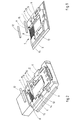
- Fig. 3 shows a perspective view of the alignment piece of Fig. 2, wherein the optical conductors are located in the alignment piece and both positioning elements are shown separated from the alignment piece.
- a second positioning means is formed in the support plate 3, 4 for the second positioning element 12, said second positioning means including two slots 15. These slots are located at the parts 8 of the alignment channels 7 in the support plate 3, 4.
- a supporting zone of the second positioning element 12 presses the optical conductors 10 in the alignment channel parts 8 of the support plate 3, 4.
- this second positioning element 12 together with the slots 15 determines the distance between the point in which the positioning element 12 engages the conductors 10, and the ends 9 of the alignment channels 7 as well as the height difference between this engaging point and these ends 9.
- Both positioning elements 11, 12 and the ends 9 of the alignment channels 7 together determine the angle of inclination of the optical conductors 10 in the alignment piece 1, 2. In this manner the angle of inclination is determined with very high accuracy.
Landscapes
- Physics & Mathematics (AREA)
- General Physics & Mathematics (AREA)
- Optics & Photonics (AREA)
- Mechanical Coupling Of Light Guides (AREA)
- Optical Couplings Of Light Guides (AREA)
Applications Claiming Priority (2)
| Application Number | Priority Date | Filing Date | Title |
|---|---|---|---|
| NL9500329A NL9500329A (nl) | 1995-02-21 | 1995-02-21 | Positioneringsstuk voor optische geleiders. |
| NL9500329 | 1995-02-21 |
Publications (2)
| Publication Number | Publication Date |
|---|---|
| EP0729046A1 true EP0729046A1 (fr) | 1996-08-28 |
| EP0729046B1 EP0729046B1 (fr) | 2003-05-02 |
Family
ID=19865616
Family Applications (1)
| Application Number | Title | Priority Date | Filing Date |
|---|---|---|---|
| EP96200255A Expired - Lifetime EP0729046B1 (fr) | 1995-02-21 | 1996-02-06 | Dispositif d'alignement pour des conducteurs optiques |
Country Status (4)
| Country | Link |
|---|---|
| US (1) | US5655045A (fr) |
| EP (1) | EP0729046B1 (fr) |
| DE (1) | DE69627740T2 (fr) |
| NL (1) | NL9500329A (fr) |
Cited By (1)
| Publication number | Priority date | Publication date | Assignee | Title |
|---|---|---|---|---|
| WO2002056078A1 (fr) * | 2001-01-11 | 2002-07-18 | Schott Glas | Procede et dispositif de positionnement de guides d'ondes optiques |
Families Citing this family (13)
| Publication number | Priority date | Publication date | Assignee | Title |
|---|---|---|---|---|
| US6198580B1 (en) | 1998-08-17 | 2001-03-06 | Newport Corporation | Gimballed optical mount |
| US6516130B1 (en) | 1998-12-30 | 2003-02-04 | Newport Corporation | Clip that aligns a fiber optic cable with a laser diode within a fiber optic module |
| FR2790115B1 (fr) | 1999-02-23 | 2001-05-04 | Micro Controle | Procede et dispositif pour deplacer un mobile sur une base montee elastiquement par rapport au sol |
| US6996506B2 (en) | 1999-02-23 | 2006-02-07 | Newport Corporation | Process and device for displacing a moveable unit on a base |
| US6511035B1 (en) | 1999-08-03 | 2003-01-28 | Newport Corporation | Active vibration isolation systems with nonlinear compensation to account for actuator saturation |
| US6655840B2 (en) | 2001-02-13 | 2003-12-02 | Newport Corporation | Stiff cross roller bearing configuration |
| US6601524B2 (en) | 2001-03-28 | 2003-08-05 | Newport Corporation | Translation table with a spring biased dovetail bearing |
| US6791058B2 (en) | 2001-04-25 | 2004-09-14 | Newport Corporation | Automatic laser weld machine for assembling photonic components |
| US6568666B2 (en) | 2001-06-13 | 2003-05-27 | Newport Corporation | Method for providing high vertical damping to pneumatic isolators during large amplitude disturbances of isolated payload |
| US6619611B2 (en) | 2001-07-02 | 2003-09-16 | Newport Corporation | Pneumatic vibration isolator utilizing an elastomeric element for isolation and attenuation of horizontal vibration |
| US6966535B2 (en) | 2002-05-07 | 2005-11-22 | Newport Corporation | Snubber for pneumatically isolated platforms |
| US7320455B2 (en) | 2003-10-24 | 2008-01-22 | Newport Corporation | Instrumented platform for vibration-sensitive equipment |
| US8231098B2 (en) | 2004-12-07 | 2012-07-31 | Newport Corporation | Methods and devices for active vibration damping of an optical structure |
Citations (6)
| Publication number | Priority date | Publication date | Assignee | Title |
|---|---|---|---|---|
| US4045121A (en) * | 1976-01-22 | 1977-08-30 | The Deutsch Company Electronic Components Division | Optical fiber connector |
| FR2660442A1 (fr) * | 1990-04-02 | 1991-10-04 | Cabloptic Sa | Procede et dispositif pour aligner des fibres optiques. |
| EP0497011A1 (fr) * | 1991-01-29 | 1992-08-05 | BELL TELEPHONE MANUFACTURING COMPANY Naamloze Vennootschap | Assemblage de circuit imprimé |
| EP0530875A1 (fr) * | 1991-08-09 | 1993-03-10 | BELL TELEPHONE MANUFACTURING COMPANY Naamloze Vennootschap | Structure de couplage optique, substrat pour celle ci et méthode de réalisation d'une telle structure |
| EP0571037A1 (fr) * | 1992-05-20 | 1993-11-24 | Framatome Connectors International | Assemblage de connecteur |
| EP0602726A1 (fr) * | 1992-12-16 | 1994-06-22 | Framatome Connectors International | Assemblage de connecteur |
Family Cites Families (10)
| Publication number | Priority date | Publication date | Assignee | Title |
|---|---|---|---|---|
| CA1283569C (fr) * | 1986-03-14 | 1991-04-30 | Toshiaki Kakii | Raccord et dispositif pour epissure de fibres optiques |
| NL9100424A (nl) * | 1991-03-08 | 1992-10-01 | Nederland Ptt | Werkwijze voor het positioneren en fixeren van optische vezels in een optische vezelrij en een koppelinrichting voorzien van een dergelijke vezelrij. |
| US5185846A (en) * | 1991-05-24 | 1993-02-09 | At&T Bell Laboratories | Optical fiber alignment apparatus including guiding and securing plates |
| US5155787A (en) * | 1991-09-06 | 1992-10-13 | Minnesota Mining And Manufacturing Company | Multiple optical fiber splice element having ramped porch |
| FR2698452B1 (fr) * | 1992-11-25 | 1995-01-13 | Mars Actel | Dispositif de positionnement et de retenue en nappe de fibres optiques. |
| NL9202172A (nl) * | 1992-12-16 | 1994-07-18 | Framatome Connectors Belgium | Connectorsamenstel. |
| US5400426A (en) * | 1993-08-19 | 1995-03-21 | Siecor Corporation | Fiber optic mechanical splice having grooves for dissipating index matching material impurities |
| FR2719912B1 (fr) * | 1994-05-10 | 1996-06-21 | Radiall Sa | Dispositif de connexion de fibres optiques à des guides d'ondes formés dans un substrat. |
| US5440657A (en) * | 1994-05-26 | 1995-08-08 | The Whitaker Corporation | Re-enterable splicer for ribbon fiber |
| US5519798A (en) * | 1994-08-15 | 1996-05-21 | At&T Corp. | Optical fiber connector including V-groove/pin alignment means |
-
1995
- 1995-02-21 NL NL9500329A patent/NL9500329A/nl not_active Application Discontinuation
-
1996
- 1996-02-06 EP EP96200255A patent/EP0729046B1/fr not_active Expired - Lifetime
- 1996-02-06 DE DE69627740T patent/DE69627740T2/de not_active Expired - Fee Related
- 1996-02-14 US US08/601,256 patent/US5655045A/en not_active Expired - Fee Related
Patent Citations (6)
| Publication number | Priority date | Publication date | Assignee | Title |
|---|---|---|---|---|
| US4045121A (en) * | 1976-01-22 | 1977-08-30 | The Deutsch Company Electronic Components Division | Optical fiber connector |
| FR2660442A1 (fr) * | 1990-04-02 | 1991-10-04 | Cabloptic Sa | Procede et dispositif pour aligner des fibres optiques. |
| EP0497011A1 (fr) * | 1991-01-29 | 1992-08-05 | BELL TELEPHONE MANUFACTURING COMPANY Naamloze Vennootschap | Assemblage de circuit imprimé |
| EP0530875A1 (fr) * | 1991-08-09 | 1993-03-10 | BELL TELEPHONE MANUFACTURING COMPANY Naamloze Vennootschap | Structure de couplage optique, substrat pour celle ci et méthode de réalisation d'une telle structure |
| EP0571037A1 (fr) * | 1992-05-20 | 1993-11-24 | Framatome Connectors International | Assemblage de connecteur |
| EP0602726A1 (fr) * | 1992-12-16 | 1994-06-22 | Framatome Connectors International | Assemblage de connecteur |
Cited By (1)
| Publication number | Priority date | Publication date | Assignee | Title |
|---|---|---|---|---|
| WO2002056078A1 (fr) * | 2001-01-11 | 2002-07-18 | Schott Glas | Procede et dispositif de positionnement de guides d'ondes optiques |
Also Published As
| Publication number | Publication date |
|---|---|
| NL9500329A (nl) | 1996-10-01 |
| DE69627740D1 (de) | 2003-06-05 |
| DE69627740T2 (de) | 2004-01-29 |
| US5655045A (en) | 1997-08-05 |
| EP0729046B1 (fr) | 2003-05-02 |
Similar Documents
| Publication | Publication Date | Title |
|---|---|---|
| US5655045A (en) | Alignment piece for optical conductors | |
| EP0571037B1 (fr) | Assemblage de connecteur | |
| US4279468A (en) | Optical fiber connectors | |
| US4077695A (en) | Termination means for ribbon cables | |
| US4464002A (en) | Electrical connector | |
| JPS6267471A (ja) | 印刷回路板等の電子的試験装置 | |
| DE3782624D1 (de) | Verbindungselement fuer lichtwellenleiter. | |
| TW333617B (en) | Fiber optic connector element | |
| US4161347A (en) | Connector for an optical fibre link | |
| DE3578230D1 (de) | Verbinder fuer die kupplung zwischen optischen fasern. | |
| US4533129A (en) | Electrical connector locator plate | |
| EP0099684A1 (fr) | Ensemble de gabarit de localisation | |
| US5009605A (en) | Flat electrical connector assembly with precisely aligned soldering traces | |
| SE453032B (sv) | Kombination av kontaktdon | |
| AU4861090A (en) | Low insertion force connector and electrical contact therefor | |
| EP0701152A1 (fr) | Dispositif d'alignement pour un connecteur de conducteurs optique | |
| US6425693B2 (en) | Optical fiber connector | |
| EP0701153B1 (fr) | Dispositif d'alignement pour un connecteur des conducteurs optique | |
| JP4079567B2 (ja) | 配線固定具 | |
| EP0701154B1 (fr) | Pièce d'alignment pour un connecteur des guides optiques | |
| JPH0360089B2 (fr) | ||
| DE59000028D1 (de) | Rohrverbindung zwischen zwei stumpf miteinander zu verbindenden rohrenden. | |
| EP0330009A3 (fr) | Connecteur pour câbles plats à constante diélectrique basse | |
| EP0766839A1 (fr) | Ensemble connecteur | |
| IT8919712A0 (it) | Connettore elettrico con elementi di serraggio a settori curvi. |
Legal Events
| Date | Code | Title | Description |
|---|---|---|---|
| PUAI | Public reference made under article 153(3) epc to a published international application that has entered the european phase |
Free format text: ORIGINAL CODE: 0009012 |
|
| AK | Designated contracting states |
Kind code of ref document: A1 Designated state(s): BE DE FR NL SE |
|
| 17P | Request for examination filed |
Effective date: 19960918 |
|
| 17Q | First examination report despatched |
Effective date: 20010904 |
|
| GRAH | Despatch of communication of intention to grant a patent |
Free format text: ORIGINAL CODE: EPIDOS IGRA |
|
| GRAH | Despatch of communication of intention to grant a patent |
Free format text: ORIGINAL CODE: EPIDOS IGRA |
|
| GRAA | (expected) grant |
Free format text: ORIGINAL CODE: 0009210 |
|
| AK | Designated contracting states |
Designated state(s): BE DE FR NL SE |
|
| PG25 | Lapsed in a contracting state [announced via postgrant information from national office to epo] |
Ref country code: NL Free format text: LAPSE BECAUSE OF FAILURE TO SUBMIT A TRANSLATION OF THE DESCRIPTION OR TO PAY THE FEE WITHIN THE PRESCRIBED TIME-LIMIT Effective date: 20030502 |
|
| REF | Corresponds to: |
Ref document number: 69627740 Country of ref document: DE Date of ref document: 20030605 Kind code of ref document: P |
|
| PG25 | Lapsed in a contracting state [announced via postgrant information from national office to epo] |
Ref country code: SE Free format text: LAPSE BECAUSE OF FAILURE TO SUBMIT A TRANSLATION OF THE DESCRIPTION OR TO PAY THE FEE WITHIN THE PRESCRIBED TIME-LIMIT Effective date: 20030802 |
|
| NLV1 | Nl: lapsed or annulled due to failure to fulfill the requirements of art. 29p and 29m of the patents act | ||
| ET | Fr: translation filed | ||
| PG25 | Lapsed in a contracting state [announced via postgrant information from national office to epo] |
Ref country code: BE Free format text: LAPSE BECAUSE OF NON-PAYMENT OF DUE FEES Effective date: 20040228 |
|
| PLBE | No opposition filed within time limit |
Free format text: ORIGINAL CODE: 0009261 |
|
| STAA | Information on the status of an ep patent application or granted ep patent |
Free format text: STATUS: NO OPPOSITION FILED WITHIN TIME LIMIT |
|
| 26N | No opposition filed |
Effective date: 20040203 |
|
| BERE | Be: lapsed |
Owner name: *FRAMATOME CONNECTORS INTERNATIONAL Effective date: 20040228 |
|
| PGFP | Annual fee paid to national office [announced via postgrant information from national office to epo] |
Ref country code: FR Payment date: 20050131 Year of fee payment: 10 |
|
| PGFP | Annual fee paid to national office [announced via postgrant information from national office to epo] |
Ref country code: DE Payment date: 20050428 Year of fee payment: 10 |
|
| PG25 | Lapsed in a contracting state [announced via postgrant information from national office to epo] |
Ref country code: DE Free format text: LAPSE BECAUSE OF NON-PAYMENT OF DUE FEES Effective date: 20060901 |
|
| REG | Reference to a national code |
Ref country code: FR Ref legal event code: ST Effective date: 20061031 |
|
| PG25 | Lapsed in a contracting state [announced via postgrant information from national office to epo] |
Ref country code: FR Free format text: LAPSE BECAUSE OF NON-PAYMENT OF DUE FEES Effective date: 20060228 |