EP0729105B1 - Rechner mit Prüffunktion - Google Patents
Rechner mit Prüffunktion Download PDFInfo
- Publication number
- EP0729105B1 EP0729105B1 EP96102463A EP96102463A EP0729105B1 EP 0729105 B1 EP0729105 B1 EP 0729105B1 EP 96102463 A EP96102463 A EP 96102463A EP 96102463 A EP96102463 A EP 96102463A EP 0729105 B1 EP0729105 B1 EP 0729105B1
- Authority
- EP
- European Patent Office
- Prior art keywords
- data
- input
- key
- calculation
- check
- Prior art date
- Legal status (The legal status is an assumption and is not a legal conclusion. Google has not performed a legal analysis and makes no representation as to the accuracy of the status listed.)
- Expired - Lifetime
Links
Images


Classifications
-
- G—PHYSICS
- G06—COMPUTING OR CALCULATING; COUNTING
- G06F—ELECTRIC DIGITAL DATA PROCESSING
- G06F15/00—Digital computers in general; Data processing equipment in general
- G06F15/02—Digital computers in general; Data processing equipment in general manually operated with input through keyboard and computation using a built-in program, e.g. pocket calculators
- G06F15/025—Digital computers in general; Data processing equipment in general manually operated with input through keyboard and computation using a built-in program, e.g. pocket calculators adapted to a specific application
- G06F15/0283—Digital computers in general; Data processing equipment in general manually operated with input through keyboard and computation using a built-in program, e.g. pocket calculators adapted to a specific application for data storage and retrieval
Definitions
- the present invention relates to computers, and more particularly to a computer which has the functions of performing a calculating operation on an input series of calculation expression data, storing same and comparing the stored data with a series of calculation expression data input next to thereby perform a check operation.
- a computer has been considered which has the function of checking the result of a calculation under control thereof.
- This computer sequentially stores a series of calculation expression data input first, and makes a calculation on the data to obtain the result of the calculation. Execution of the check operation is then designated.
- a second series of calculation expression data which is believed to be the same as the first input series of calculation expression data is newly input and compared sequentially with the stored first series of calculation expression data. As a result, if the first series of calculation expression data is not coincident with the second series of calculation data, this fact is reported to the outside.
- the computer of this type stores all the first input series of calculation expression data as it is, inclusive of even data unrelated to the actual calculation.
- the check operation is performed, exactly the same input operation as that first performed is required to be performed on even first input data unrelated to the calculation, if any.
- DE 37 25 284 A1 describes such a computer that is tailored to summing up a series of input data.
- This computer comprises input means and an additional storage means, containing at least two different registers for sequentially storing a first input data series and the corresponding intermediate sums while respecting the order of input.
- a second data input series that is supposed to be identical to the first data input series will then be entered. While entering this second data input series, each data input value or intermediate sum can be compared by a comparison means to the already stored corresponding first input value or intermediate sum, which is supposed to be identical.
- the present invention provides a computer comprising:
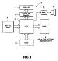
- FIG. 1 is block diagram indicative of the basic structure of the computer of this embodiment.
- the computer 1 of FIG. 1 is composed of a central processing unit (CPU) 2 which controls the whole computer 1 in accordance with program commands, a read only memory (ROM) 3 which contains microprograms processed by the CPU 2, a random access memory (RAM) 4 which stores data, a key-in unit 5 which is used to key in data and to select a mode to be described later, a display driver 6 and a display 7 which display numerical data and various message data output from the CPU 2, an amplifier 8 and a speaker 9 which respectively amplify a reporting sound signal from the CPU 2 and output a corresponding sound.
- CPU central processing unit
- ROM read only memory
- RAM random access memory
- key-in unit 5 which is used to key in data and to select a mode to be described later
- a display driver 6 and a display 7 which display numerical data and various message data output from the CPU 2
- an amplifier 8 and a speaker 9 which respectively amplify a reporting sound signal from the CPU 2 and output a corresponding sound.
- the RAM 4 includes a display register area 10 (which acts also as an input numeral register area) which stores data displayed on the display 7, a calculation register area 11 which temporarily stores numerical values processed by the CPU 2, a memory register area 12 which temporarily stores the result of the calculation, and a flag register area 13 which stores various condition flags F, H, M indicative of corresponding conditions in the execution of a program.
- a display register area 10 which acts also as an input numeral register area
- a calculation register area 11 which temporarily stores numerical values processed by the CPU 2
- a memory register area 12 which temporarily stores the result of the calculation
- a flag register area 13 which stores various condition flags F, H, M indicative of corresponding conditions in the execution of a program.
- RAM 4 includes a journal memory area 14 which temporarily stores the input data from the key-in unit 5, and a pointer area 15 which stores an address pointer P n indicative of a respective one of the registers in the journal memory area 14.
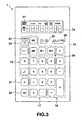
- the key-in unit 5 includes a numeral inputting key group 17, calculation command key groups 18, 19, a memory key group 20, a clear "C” key 21, an all-clear “AC” key 22, a place down “ ⁇ ” key 23, and a check key 24, provided on the control panel 16 of the computer 1.
- the numeral inputting key group 17 includes numeral keys "0"-"9" used to input corresponding numerical values "0"-"9" and a decimal point ".” key to input a decimal point.
- the calculation command key group 19 includes a positive/negative "+/-” key used to change the (positive/negative) sign of a displayed numerical value, a percent “%” key used to make a percent calculation, a root calculation " ⁇ " key used to make a square root calculation.
- the memory key group 20 includes a memory plus "M+” key used to add a displayed numerical value (or input the displayed numerical value with a plus sign) to the numerical value stored in the memory register, a memory minus “M-” key used to subtract a displayed numerical value from the numerical value stored in the memory register (or input the displayed numerical value with a minus sign to the numerical value stored in the memory register), a memory recall "MR” key used to call back a numerical value stored in the memory register, and a memory recall/clear "MC” key used to recall and simultaneously erase a numerical value stored in the memory register.
- M+ memory plus "M+” key used to add a displayed numerical value (or input the displayed numerical value with a plus sign) to the numerical value stored in the memory register
- a memory minus “M-” key used to subtract a displayed numerical value from the numerical value stored in the memory register (or input the displayed numerical value with a minus sign to the numerical value stored in the memory register)
- a memory recall "MR” key used to call back
- the "C” key 21 is used to correct a wrongly keyed-in numerical value.
- the "AC" key 22 is used to erase (initialize) all data input and calculated so far.
- the " ⁇ " key 23 is used to erase the displayed least significant place of a displayed numerical value. Each time this key is depressed, the number of places of the numerical value concerned is reduced by one. This key is also used to alternately display in the check mode the results of calculations performed this time and last time.
- the check key 24 is a command key used to alternately select a standard or regular calculation mode and a check mode.
- the round switch 25 designates how a fraction should be processed and can designate any one of a free mode "F" in which the result of the calculation is obtained to as many decimal places as desired, a cut mode "C” in which a place directly below a decimal place designated by the decimal point designation switch 26 is discarded, and a round "5/4" mode in which the result of the calculation is rounded off to designated decimal places by counting fractions of 0.5 and over as a unit and cutting away the rest.
- the decimal point designating switch 26 is effective when the round switch 25 is in the cut "C” mode or the round "5/4" mode to designate any one of a "0" place mode which implies performing no calculation down to any decimal places; a "1" mode which implies performing calculation down to one decimal place; a "2" mode which implies performing calculation down to two decimal places; and a "4" mode which implies performing calculation down to four decimal places.
- the decimal point designating switch 39 is also capable of designating a fixed decimal point "ADD 2" mode in which a decimal point is put automatically in a numerical value so that the numerical value has two decimal places even when the ".” key is not depressed.
- the display 7 is composed of a well-known liquid crystal display.
- the display 7 is driven by the driver 6 to display numerical data such as input numerical value and the answer concerned, various message data, etc., thereon.
- the display window 7a is provided above the input keys on the control panel 16 to display a numerical value of up to eight figures.
- M is lighted on the left side of the numerical value display area; during a constant numeral-based calculation which, for example, includes “c * y" where “c” is any constant numeral, “*” is any one of arithmetic operator symbols such as “+”, “-", “x” and “ ⁇ ”, and “y” is any variable, "K” is lighted; and when an input error such as division of any particular number by 0 occurs, "E” is lighted.
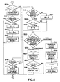
- step S2 it is determined whether the input data is based on the depression of the numeral inputting keys (step S2). If so, its numerical value is stored in the display register 10 and simultaneously displayed in the display window 7a, and the flag M becomes 1, which indicates that the numeral inputting keys have been depressed (step S3).
- step S3 When the input operations by the numeral inputting keys are performed, a corresponding numeric value of up to 8 places is displayed in the display window 7a.
- step S6 Each time a similar storage operation is repeated, the address pointer P n changes to the next address designation P n+1 (step S6). Thus, the calculations for the input calculation data and their results are displayed sequentially, and the answer is finally displayed in the displayed window 7a (step S7). Thereafter, the flag M becomes 0 (step S8).
- step S4 When the flag M is 0 at step S4, the pointer P n points out the directly previous address designation P n-1 (step S9). Then it is determined whether the calculation command data stored in the register designated by P n and the input calculation command data are the same (step S10).
- step S10 the calculation command data stored in the register designated by P n is replaced with the input calculation command data, that is, the calculation command data produced by the later depressed calculation command key (step S11).
- the input calculation command data that is, the calculation command data produced by the later depressed calculation command key.
- the depression of the "-" key is determined to be valid and data on this key is stored in the journal register 14.
- the depression of the " ⁇ ” key is determined to ba valid and data on this key is stored in the journal register 14.
- step S10 When it is determined at step S10 that the calculation command data stored in the registers designated by P n and input calculation command data are the same, it is then determined at step S12 whether the current state is a data lock one where numeral data and following calculation command sign data are locked. If so, the data lock state is released (step S13). If not at step S12, a data lock state occurs (step S14).
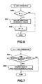
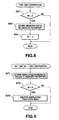
- step S40 When the "C” key 21 is depressed in the course of the key-in operation in the regular calculation mode, the "C” key operation routine (FIG. 7) is performed.
- step S41 the displayed numerical values are deleted (step S41) and the flag M becomes 0 (step S42).
- step S51 When the "+/-" key is then depressed, the "+/" key operation routine (FIG. 7) is performed.
- step S51 When it is then determined at step S51 that a numerical value has been displayed, the sign "+” or "-" of the numerical value displayed in the display window 7a is changed (step S52).
- step S61 When the "MR” key is depressed, the "MR” key operation routine (FIG. 8) is performed.
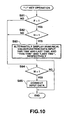
- the least significant place of the numerical value displayed in the display window 7a is erased (step S85).
- the data keyed in by the " ⁇ " key 23 is used for the purpose of correction. In the calculation, only the corrected data is valid, so that the data keyed in by the " ⁇ " key 23 is not stored in the journal memory 14.
- step S91 it is determined whether the current mode is the regular operation mode, and "PROVING" is displayed in the message display area of the display window 7a (step S9).
- the flag F becomes "1", which implies the check mode (steps S93, S94).
- the mode is determined to be the check mode at step S1 of the numeral inputting key/function key operation routine (FIGS. 4 and 5).
- H 0, i.e., whether the mode is a correction one.
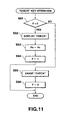
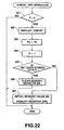
- step S16 When it is determined at step S16 that the calculation command key has been operated, it is determined whether the current state is a data lock state (step S18). If so, it is then determined at step S19 whether the flag M is 1, that is, whether numerals have been keyed in by the numeral inputting keys. If so, the flag M becomes 0 (step S20) and the control is then put in the input wait state.
- step S18 When it is determined at step S18 that the state is not the data lock state, and the flag M then becomes 0 (step S21), the numerical value/calculation command data newly input this time is compared with that stored last time in the register of the journal memory 14 designated by P n for the purpose of check (step S22).
- step S19 when it is determined at step S19 that the flag M is 1, the control passes to step S22.
- step S23 When the newly input numerical value/calculation command data coincides with the previous one stored in the journal memory 14, the address pointer P n becomes the next address designation P n+1 (step S23). Thus, the required calculation and the display of the result of the calculation are performed (step S24).
- step S22-S24 Each time the operation of numeral inputting keys and a calculation command key is performed, the newly input numeral value/calculation command data is compared with the numerical value/calculation command data stored in a respective one of the registers of the journal memory 24 designated by P n . If both coincide, the required calculation and display of the result of the calculation are performed (steps S22-S24).
- step S22 When it is determined at step S22 that the newly input numerical value/calculation command data does not coincide with the previous numerical value/calculation command data stored in the register of the journal memory 14 designated by P n , an alarm sound "pi, pi, pi" is generated from the speaker 7 (step S27), and the non-coincident input data is displayed in a blinking manner in the display window 7a (step S28). Thereafter, the flag H becomes "1", i.e., the mode becomes the correction mode (step S29). "THIS TIME" is then displayed in the message display area of the display window 7a (step S30).
- step S81 of the " ⁇ " key operation routine (FIG. 10) that the current mode is the check mode. It is then determined at step S82 that the current mode is the correction mode.
- step S83 the numerical value /calculation command signs input last time and this time are displayed alternately and "LAST TIME” and “THIS TIME” "are correspondingly displayed alternately (step S83).
- a correction process is performed at step S31 of the numerical inputting key/function key operation routine.
- correct data is then input by the numeral inputting keys or the calculation command key, it is determined at step S32 that the calculation command key is operated.
- the flag H becomes "0”, and the correction mode ends (steps S33).
- step S31 the corresponding data in the journal memory is rewritten with the corrected data.
- the address pointer P n then becomes the next address designation P n+1 (step S34), the required calculation is performed, and the display of the result of the calculation is performed (step S35).
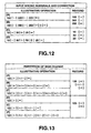
- FIGS. 12 and 18 show illustrative key-in operations and the corresponding illustrative recording in the journal memory 14 in the regular calculation mode.
- FIG. 12A shows an illustrative operation in which no input mistake has been made while FIG. 12B shows that a mistake has been made in the same numeral inputting operation as that in FIG. 12A.
- FIG. 12B shows that a mistake has been made in the same numeral inputting operation as that in FIG. 12A.
- the " ⁇ " key 23 was operated, the least significant figure “2" of the numerical value "202" displayed at that time was erased and a correct numerical value "0" was input.
- the data keyed in by the " ⁇ " key 23 and the erased numerical value "2" data are determined to be invalid and not stored in the journal memory 14.
- FIG. 12C shows an illustrative operation in which no input mistake has been made while FIG. 12D shows that a mistake has been made in the same numeral inputting operation as that in FIG. 12C.
- the "C” key 21 was operated to erase the numerical value "50” displayed at that time and a correct numerical value "20" was input.
- the data keyed in by the "C” key 21 and the numerical value "50" data erased by the "C” key 21 were cleared in the correction. Thus, they were determined to be invalid in the calculation and not stored in the journal memory 14.
- FIG. 13 shows an illustrative operation including switching the sign of a numerical value by the "+/-" key.
- (A) to (F) of FIG. 13 show the cases where the "+/-" key was operated an odd number of times while (D) to (F) of FIG. 13 show the cases where the "+/-" key was operated an even number of times.
- FIG. 13 show that the "+/-" key was operated once, three times and four times, respectively. In any one of these cases, only the data keyed in last by the "+/-" key is determined to be valid and stored in the journal memory 14.
- FIG. 14 shows illustrative operations of the computer including a release operation performed when an error (or an input invalidation state) due to an inhibit operation has occurred.
- (A) of FIG. 14 shows an illustrative operation including removal of an error which has been caused by a calculation for a numerical value exceeding a maximum numerical value which the computer 1 is able to process.
- "2" was added to a maximum numerical value "99...9” to find the answer and the "C” key 21 was then depressed for removing an error which occurred.
- the data keyed in by the "C” key was determined to be invalid and was not stored in the journal memory 14.
- FIG. 14 shows an illustrative operation including removal of an error which occurred due to an meaningless operation which included the division of a numerical value by 0.
- "100" was divided by "0" to find the answer and the "C” key 21 was depressed to eliminate the error.
- the data keyed in by the "C” key 21 was determined to be invalid and was not stored in the journal memory 14.
- (C) of FIG. 14 shows an illustrative operation including removal of an error which occurred due to an invalid operation which includes extraction of the square root of a negative number.
- the square root of "-2" was extracted and the "C” key 21 was depressed to eliminate the error.
- the data keyed in by the "C" key 21 was determined to be invalid and was not stored in the journal memory 14.
- FIG. 15 shows an illustrative operation which includes the update and correction of a wrong operation command (function) based on the depression of a wrong calculation command key by the depression of a correct calculation command key.
- FIG. 16 shows an illustrative operation including a data lock operation.
- (A) and (B) of FIGS. 16 each show the case where the calculation command key was operated an even number of times while (C) and (D) of FIG. 16 each show the case where the calculation command key was operated an odd number of times.
- FIG. 17 shows illustrative operations including keying operations invalidated by the subsequent key-in operation.
- the directly proceeding numeral data "12" was invalidated.
- the directly preceding data input by the "+/-” key was invalidated.
- the same keyed-in data as that in (C) of FIG. 17 was stored in the journal memory 14.
- (D) of FIG. 17 shows that numerical data "786" was keyed in after the operation of the "+/-” key so that the data keyed in by the "+/-” key was invalidated.
- the same keyed-in data as that in the case of (E) of FIG. 17 which involved no operation of the "+/-" key was stored in the journal memory 14.
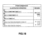
- FIG. 18 shows illustrative operations of other keys.
- (A) and (B) of FIG. 18 show that the "MR" key was operated three times and twice, respectively. In any of those cases, only the data keyed in by the last operation is determined to be valid. This state is the same as that obtained by the single operation of the "MR" key, as in (C) of FIG. 18. In this case, the data stored in the "MR” (shown as [MR] in FIG. 18) is stored in the journal memory 14.
- FIG. 18 shows that the " ⁇ " key and the "+” key were operated in succession, that the calculation command was updated by the "+” key, and the "C” key was then depressed to erase the data keyed in by the "x” key.
- the data keyed in by the "+” key was determined to be invalid when the "x” key was depressed
- the data keyed in by the "x” key was determined to be invalid when the "C” key was depressed
- the data keyed in by the "C” was determined to be invalid.
- no data which was determined to be invalid is stored in the journal memory 14.
- FIG. 18 shows that the " ⁇ " key and "C” key were operated in succession. In this case, the data keyed in by the "C” key was determined to be invalid and not stored in the journal memory 14.
- invalid input data required for calculation in the regular calculation mode is not stored in the journal memory 14, but only valid data is stored.
- a useless key-in operation is omitted and operability is improved.
- journal memory area 14 is reduced compared to the conventional one, and the differential storage area between the original and reduced storage area can be used effectively as another data storage area.
- the use of a RAM 4 having a reduced capacity compared to the conventional one may reduce the cost of the articles.
- circuit configuration and external structure of a computer as the second embodiment of the present invention are the same as FIGS. 1 and 3, respectively, and further description thereof will be omitted.
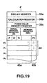
- FIG. 19 shows the register structure of a RAM 4' of the computer as the second embodiment.
- the RAM 4' includes a display register 33a which stores, as bit map data, data to be displayed on a liquid crystal display 7a, a calculation register 33b which temporarily stores operands and operators involved in the course of the calculation process and the results of the calculations; a fixed value memory 33c in which calculation data fixed in accordance with the operations of function keys in the check/correction mode are sequentially stored and updated; a journal memory 40 which includes pairs of a numeral register 40a and a function register 40b in which corresponding pairs of numerical data involved and function data which constitute calculation data are sequentially stored in accordance with the calculations concerned; a memory register MR which stores numerical data involved in a memory calculation which includes the operation of a memory function key group 15; an initial memory register M which stores numerical data transferred from the memory register MR when the "AC (all clear) key" is operated at the beginning of the calculation; a check mode register F in which a flag is set in the set check mode; a correction mode register H in which a flag is set in a set correction mode; a correction
- a speaker 9 generates a sound confirming a key operation and a sound reporting that calculation data which is not coincident with the preceding data has been input in the check mode.
- step T1 ⁇ T2 ⁇ T3 it is determined whether a numeral inputting key has been operated, so that the keyed-in numeral data is written into the display register 33a of RAM 4' and displayed in the numeral/sign display area of the liquid crystal display 7a (step T1 ⁇ T2 ⁇ T3).
- calculation data composed of pairs of a numeral and a function are stored in the registers of the journal memory 40 designated by sequentially by the pointer register P n , the corresponding calculation is performed, and the result of the calculation is displayed (steps T1-T7).
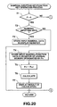
- step A5 When it is determined at step A5 that the answer is "NO”, that is, that no function data indicative of "MC" has been stored at address P0 in the journal memory 40, and that the "MC" key had not been operated first when the first calculation expression was input, the data in the memory register MR at the beginning of the inputting operation of data on the first calculation expression becomes the initial memory value stored in the initial memory register M. Thus, the initial value stored in the initial memory register M is transferred to and set in the memory register M (step A5 ⁇ A7).
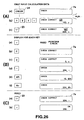
- numeral keys and an operator key can be operated to input, for example, "123" and "+”, as shown in FIG. 26A[b].
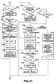
- the computer control shifts to the check mode process of FIG. 21, where it is determined whether "1" has been set in the correction mode register H, that is, the computer has been set in the correction mode (step T1 ⁇ T8).
- step T12 ⁇ T13, T14, T15 the value n of the pointer register P n for the journal memory 40 is incremented by one, a calculation process for the calculation data input this time and determined to be coincident is performed and data on the result of the calculation is displayed in the display 7a (step T12 ⁇ T13, T14, T15).
- step T12 Each time a function key is operated which involves in the inputting operation of the calculation expression to be checked this time, it is determined whether the one-unit calculation data input this time coincides with corresponding data of the calculation expression input last time (step T1 ⁇ T8 to T16 ⁇ T1).
- step T12 determines whether the one-unit calculation data input this time coincides with corresponding data of the calculation expression input last time (step T1 ⁇ T8 to T16 ⁇ T1).
- the display 7a displays calculation data "123" "+” input this time and determined to be non-coincident with the data stored in the journal memory 40, the "MESSAGE INPUT THIS TIME” indicative of the calculation data input this time, and a "CORRECT” message indicating that the correction mode has been set now (step T18).
- the correction mode setting flag is set at "1" in the correction mode register H of RAM 4', and the operational mode of the CPU 2 is changed to the correction mode (step T19).
- the operation of the "+" key is determined to be the operation of a function key accompanied by no numerals in the correction process of FIG. 23.
- the function data of the calculation data displayed at present is changed to data "+", which is then displayed (unchanged in this case).
- a calculation process for the corrected and fixed calculation data is then performed and data on the result of the calculation is then displayed (steps T24, 25).
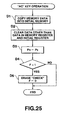
- step T21 the corrected and fixed calculation data stored in the fixed value memory register 33c of RAM 4' is read and displayed, for example, as "234" "-" in the display 12 (step C1 ⁇ C2 ⁇ C4).
- the indication value n of the pointer P n for to the journal memory 40 of RAM 4' is decremented by one, the calculation data to be checked is returned to its normal state where the data is not yet fixed, the correction mode register H is again set at "1" to be thereby set the correction mode, and a message "CORRECT" is again displayed on the display 12 (steps C5,C6).
- control since it is determined that no function key has been operated, the control passes to a step where the control waits for the next depression of numeral inputting keys or a function key (step TB ⁇ T20 ⁇ T1).
- the corrected and fixed calculation data "234" "-” is stored in the fixed value memory register 33c and "0" is set in the correction mode register H to thereby erase the message "CORRECT" (step TB ⁇ T20 ⁇ T21, T22).
- the corrected and fixed calculation data "234" "M+” is stored in the fixed value memory register 33c and "0" is set in the correction mode register H to thereby erase the message "CORRECT" (step TB ⁇ T20 ⁇ T21, T22).
- a calculation process is performed in accordance with the calculation expression input this time on the basis of the corrected fixed series of calculation data, and data on the result of the calculation is displayed. In addition, it is determined that the check operation has ended. It is then determined whether "0" has been set in the correction non-coincidence register N, that is, whether the correction process has been started due to non-coincidence of the calculation expression input this time and the calculation expression data input last time (step T11-T14, T15, T16-T26).
- the memory register MR When it is determined that at step A5 ⁇ A6 of the " ⁇ " key operation of FIG. 22 that there is function data corresponding to the "MC" key at an address P0 of the journal memory 40, the memory register MR is cleared. This is because when calculation expression data is input after the check mode has been set, the memory register MR can be set at the same memory conditions as the initial conditions of the calculation expression input last time even when the depression of the "MC" key is forgotten.
- calculation data at address P1 in the journal memory 40 is set as calculation data for the calculation expression and compared with the head calculation data for the calculation expression input this time, at step T12 of the check mode process of FIG. 21.
- step D1 When the "AC" key of the key-in unit 5 is depressed, numerical data stored in the memory register MR of RAM 33 is transferred as a memory value at the beginning of the calculation to and stored in the initial memory register M, and all the data except for data in the memory register MR and the initial memory register M is cleared (steps D1, D2).
- the indication value of the pointer register P n for the journal memory 40 is reset at P0 (step D3).
- the calculation data "234" "+” input last time is compared to the calculation data "234" "-” input this time.
- the correction mode is set and the message "CORRECT" is displayed.
- a correct "+” or "-” function key is depressed in the set correction mode, only the function data of the calculation data "234" "-” which was determined to be non-coincident is corrected, the resulting correct data is then displayed, the message "CORRECT" is erased, and the correction mode is released.
- all the calculation data which includes data on a set of numerals and functions is not necessarily required to be all erased or reinput, but only function data can be reinput for the purpose of correction.
- the correction mode is set and the message "CORRECT" is displayed.
- correct numerical data for example, "2"
- incorrect numerical data of the calculation data "123" "+” which was determined to be non-coincident is replaced with input correct numerical data "2”, and the resulting calculation data is displayed.
- the message "CORRECT” is erased and the correction mode is released.
Landscapes
- Engineering & Computer Science (AREA)
- Theoretical Computer Science (AREA)
- Computing Systems (AREA)
- Computer Hardware Design (AREA)
- Physics & Mathematics (AREA)
- General Engineering & Computer Science (AREA)
- General Physics & Mathematics (AREA)
- Calculators And Similar Devices (AREA)
- Input From Keyboards Or The Like (AREA)
Claims (14)
- Computer, der aufweist:gekennzeichnet durch:eine Eingabeeinrichtung (5) zum Eingeben von nummerischen Daten und von Funktionsdaten;eine Funktionssteuereinrichtung (S7) zum Durchführen eines Berechnungsvorgangs in Bezug auf die nummerischen Daten, eingegeben durch die Eingabeeinrichtung (5), auf der Basis der Eingabefunktionsdaten;eine Speichereinrichtung (14) zum Speichern der Daten, eingegeben durch die Eingabeeinrichtung (5);eine Prüfeinstelleinrichtung (24) zum Einstellen eines Prüfmodus; undeine Prüfeinrichtung zum Vergleichen von Daten, gespeichert in der Speichereinrichtung (14), und von neu eingegebenen Daten durch die Eingabeeinrichtung (5) in einem Prüfmodus, eingestellt durch die Prüfeinstelleinrichtung (24), um darüber zu berichten, dass die früheren Daten nicht mit den späteren Daten übereinstimmen, wenn diese Nicht-Übereinstimmung existiert,eine Bestimmungseinrichtung zum Bestimmen, ob die Daten, eingegeben durch die Eingabeeinrichtung (5), nicht in Bezug stehende Daten sind, die nicht zu einer vorbestimmten Berechnung in Bezug gesetzt sind, die dann durchgeführt werden soll, wenn die zuletzt erwähnten Daten in der Speichereinrichtung (14) gespeichert sind; undeine Speichersteuereinrichtung zum Steuern der Speichereinrichtung (14) so, dass nummerische Daten und Funktionsdaten, die dahingehend bestimmt sind, dass sie nicht die nicht in Bezug stehenden Daten sind, in der Speichereinrichtung (14) gespeichert werden, und solche, die dahingehend bestimmt sind, dass sie die nicht in Bezug gesetzten Daten sind, nicht in der Speichereinrichtung (14) gespeichert werden.
- Computer nach Anspruch 1, wobei die Bestimmungseinrichtung eine Einrichtung zum Bestimmen aufweist, ob die Daten, eingegeben durch die Eingabeeinrichtung (5), gültig für die Berechnung sind, auf der Basis der Beziehung zwischen den Eingabedaten und anderen Daten, eingegeben vor den früheren Eingabedaten.
- Computer nach Anspruch 1, wobei die Bestimmungseinrichtung eine Einrichtung zum Bestimmen aufweist, ob die Daten, eingegeben durch die Eingabeeinrichtung (5), gültig für die Berechnung sind, auf der Basis der Beziehung zwischen den Eingabedaten und der Dateneingabe nach den früheren Daten.
- Computer nach Anspruch 1, wobei die Bestimmungseinrichtung eine Einrichtung zum Bestimmen aufweist, ob die Daten, eingegeben durch die Eingabeeinrichtung (5), gültig für die Berechnung sind, auf der Basis der Beziehung zwischen den Eingabedaten und den Daten, eingegeben vor oder nach den früheren Daten.
- Computer nach Anspruch 1, wobei die Bestimmungseinrichtung eine eine falsche Eingabe bestimmende Einrichtung aufweist, um falsche Daten von den Daten, eingegeben durch die Eingabeeinrichtung (5), und der Daten, eingegeben durch die Eingabeeinrichtung, zum Löschen der falschen Daten, für ungültig zu erklären.
- Computer nach Anspruch 1, wobei die Bestimmungseinrichtung eine Bestimmungseinrichtung für aktualisierte Daten aufweist, um frühere Daten, eingegeben durch die Eingabeeinrichtung (5), für ungültig zu erklären, wenn die früheren Eingabedaten durch die Daten, eingegeben von der Eingabeeinrichtung (5), aktualisiert werden.
- Computer nach Anspruch 1, wobei die Bestimmungseinrichtung eine Freigabebestimmungseinrichtung zum Bestimmen einer Ungültigkeit dieser Daten von den Daten, eingegeben durch die Eingabeeinrichtung (5), aufweist, um einen Zustand freizugeben, in dem eine Dateneingabe durch einen Unterbindungsvorgang gesperrt wird.
- Computer nach Anspruch 1, wobei die Prüfeinrichtung eine Klangerzeugungseinrichtung (8, 9) zum Erzeugen eines Klangs dann, wenn die Daten, gespeichert in der Speichereinrichtung (14), nicht mit den Daten, die neu durch die Eingabeeinrichtung (5) eingegeben sind, übereinstimmen, aufweist.
- Computer nach Anspruch 1, wobei die Prüfeinrichtung eine Anzeigeeinrichtung (7a) zum Anzeigen, dass die Daten, gespeichert in der Speichereinrichtung (14), nicht mit den Daten, die neu durch die Eingabeeinrichtung (5) eingegeben sind, übereinstimmen, wenn diese Nicht-Übereinstimmung auftritt, aufweist.
- Computer nach Anspruch 1, wobei dann, wenn die Daten, gespeichert in der Speichereinrichtung (14), nicht mit den Daten, die neu durch die Eingabeeinrichtung (5) eingegeben sind, übereinstimmen, die Prüfeinrichtung eine Korrektur-Modus-Einstelleinrichtung zum Einstellen eines Korrektur-Modus, in dem nicht-übereinstimmende Daten korrigiert werden, aufweist; und aufweist:eine Korrigiereinrichtung zum Korrigieren nur von Funktionsdaten der Daten, verglichen durch die Prüfeinrichtung mit Funktionsdaten, die neu durch die Eingabeeinrichtung (5) eingegeben sind, in dem Korrektur-Modus, eingestellt durch die Korrektur-Modus-Einstelleinrichtung; undeine Freigabeeinrichtung zum Freigeben des Korrektur-Modus, nachdem die Korrektureinrichtung nur die Funktionsdaten korrigiert hat.
- Computer nach Anspruch 10, der weiterhin aufweist:eine verglichene Daten anzeigende Einrichtung zum Anzeigen entweder der Daten, gespeichert in der Speichereinrichtung (14), oder der neu eingegebenen Daten, verglichen und bestimmt dahingehend, dass sie nicht übereinstimmend sind, durch die Prüfeinrichtung, wenn der Korrektur-Modus durch die Korrektur-Modus-Einstelleinrichtung eingestellt ist; undwobei die Korrektureinrichtung eine Funktionskorrektureinrichtung zum Korrigieren nur von Funktionsdaten der angezeigten Daten mit Funktionsdaten, eingegeben durch die Eingabeeinrichtung (5), in einem Zustand, wo Daten durch die die verglichenen Daten anzeigende Einrichtung angezeigt worden sind (FIG. 24), aufweist.
- Computer nach Anspruch 10, der eine Korrektur- und Speichersteuereinrichtung zum nochmaligen Schreiben dieser Daten von den Daten, die in der Speichereinrichtung (14) gespeichert sind, die den Daten, korrigiert durch die Korrektureinrichtung, entsprechen, mit den Daten, korrigiert durch die Korrektureinrichtung, und zum Speichern der nochmal geschriebenen Daten, aufweist.
- Computer nach Anspruch 10, wobei die Freigabeeinrichtung eine Freigabebestimmungseinrichtung zum Bestimmen des Korrektur-Modus, wenn Funktionsdaten durch die Eingabeeinrichtung eingegeben sind, aufweist.
- Computer nach Anspruch 10, wobei die Korrektur-Modus-Einstelleinrichtung eine Anzeigeeinrichtung zum Durchführen einer Anzeige entsprechend zu einem Korrektur-Modus, wenn die Korrektur-Modus-Einstelleinrichtung den Korrektur-Modus einstellt, aufweist.
Applications Claiming Priority (6)
| Application Number | Priority Date | Filing Date | Title |
|---|---|---|---|
| JP6217895 | 1995-02-24 | ||
| JP62178/95 | 1995-02-24 | ||
| JP06217895A JP3508277B2 (ja) | 1995-02-24 | 1995-02-24 | 電子計算機 |
| JP16554095A JP3557479B2 (ja) | 1995-06-30 | 1995-06-30 | 検算機能付き電子計算機 |
| JP16554095 | 1995-06-30 | ||
| JP165540/95 | 1995-06-30 |
Publications (2)
| Publication Number | Publication Date |
|---|---|
| EP0729105A1 EP0729105A1 (de) | 1996-08-28 |
| EP0729105B1 true EP0729105B1 (de) | 2004-08-11 |
Family
ID=26403237
Family Applications (1)
| Application Number | Title | Priority Date | Filing Date |
|---|---|---|---|
| EP96102463A Expired - Lifetime EP0729105B1 (de) | 1995-02-24 | 1996-02-19 | Rechner mit Prüffunktion |
Country Status (3)
| Country | Link |
|---|---|
| US (1) | US5886910A (de) |
| EP (1) | EP0729105B1 (de) |
| DE (1) | DE69633083T2 (de) |
Families Citing this family (3)
| Publication number | Priority date | Publication date | Assignee | Title |
|---|---|---|---|---|
| JP5667324B1 (ja) * | 2014-10-17 | 2015-02-12 | 晃康 加藤 | 検算機能付き電子式計算機 |
| JP6561626B2 (ja) | 2015-07-02 | 2019-08-21 | カシオ計算機株式会社 | 電子機器、計算処理方法及びプログラム |
| WO2018119760A1 (zh) * | 2016-12-28 | 2018-07-05 | 深圳配天智能技术研究院有限公司 | 一种数据输入方法、装置及设备 |
Family Cites Families (7)
| Publication number | Priority date | Publication date | Assignee | Title |
|---|---|---|---|---|
| US4291385A (en) * | 1973-12-17 | 1981-09-22 | Hewlett-Packard Company | Calculator having merged key codes |
| JPS58213369A (ja) * | 1982-06-05 | 1983-12-12 | Casio Comput Co Ltd | 検算機能付小型電子式計算機 |
| EP0264098B1 (de) * | 1986-10-14 | 1995-01-04 | Sharp Kabushiki Kaisha | Eingabesystem für eine tragbare Datenverarbeitungsanlage |
| DE3725284A1 (de) * | 1987-07-30 | 1989-02-09 | Michael Mueller | Elektronisches rechengeraet |
| JPH05204864A (ja) * | 1992-01-27 | 1993-08-13 | Sharp Corp | 関数電卓 |
| JPH0628499A (ja) * | 1992-07-07 | 1994-02-04 | Sharp Corp | データ駆動型情報処理装置 |
| JPH0830556A (ja) * | 1994-07-19 | 1996-02-02 | Masataka Ishii | 卓上電子計算器 |
-
1996
- 1996-02-12 US US08/600,398 patent/US5886910A/en not_active Expired - Lifetime
- 1996-02-19 EP EP96102463A patent/EP0729105B1/de not_active Expired - Lifetime
- 1996-02-19 DE DE69633083T patent/DE69633083T2/de not_active Expired - Lifetime
Also Published As
| Publication number | Publication date |
|---|---|
| EP0729105A1 (de) | 1996-08-28 |
| DE69633083T2 (de) | 2004-12-30 |
| US5886910A (en) | 1999-03-23 |
| DE69633083D1 (de) | 2004-09-16 |
| HK1013472A1 (en) | 1999-08-27 |
Similar Documents
| Publication | Publication Date | Title |
|---|---|---|
| EP0729105B1 (de) | Rechner mit Prüffunktion | |
| US5953734A (en) | Electronic apparatus | |
| AU2018204594B2 (en) | Graph display method, graph generating method, electronic device, and recording medium | |
| JP3508277B2 (ja) | 電子計算機 | |
| HK1013472B (en) | Computer with a check function | |
| JP4092810B2 (ja) | 演算表示装置及びプログラムを記録したコンピュータ読み取り可能な記録媒体 | |
| JP3252493B2 (ja) | 電子式計算機及びその計算処理方法 | |
| JP3557645B2 (ja) | 電子計算機 | |
| JPH08227400A (ja) | 電子計算機 | |
| JP2760277B2 (ja) | データ入出力装置 | |
| JP3509263B2 (ja) | 電子計算機 | |
| JP3786141B2 (ja) | 電子計算機および検算制御方法 | |
| JP2782245B2 (ja) | 入力操作情報による推論処理装置および方法 | |
| JPH08221368A (ja) | 電子計算機 | |
| JP2798082B2 (ja) | グラフ表示制御装置及びグラフ表示制御方法 | |
| JP2526181Y2 (ja) | 小型電子式計算機 | |
| JP3509316B2 (ja) | データ入力装置 | |
| JP2695296B2 (ja) | 計算機 | |
| JPH0916525A (ja) | 検算機能付き電子計算機 | |
| JPS642179Y2 (de) | ||
| JPS6210828Y2 (de) | ||
| JP2697901B2 (ja) | 文字処理装置 | |
| JPS6350726B2 (de) | ||
| JPH05324564A (ja) | 電子計算機 | |
| JPH08161270A (ja) | 電子計算機 |
Legal Events
| Date | Code | Title | Description |
|---|---|---|---|
| PUAI | Public reference made under article 153(3) epc to a published international application that has entered the european phase |
Free format text: ORIGINAL CODE: 0009012 |
|
| 17P | Request for examination filed |
Effective date: 19960219 |
|
| AK | Designated contracting states |
Kind code of ref document: A1 Designated state(s): DE FR GB |
|
| RAP1 | Party data changed (applicant data changed or rights of an application transferred) |
Owner name: CASIO COMPUTER CO., LTD. |
|
| 17Q | First examination report despatched |
Effective date: 19991112 |
|
| GRAP | Despatch of communication of intention to grant a patent |
Free format text: ORIGINAL CODE: EPIDOSNIGR1 |
|
| GRAP | Despatch of communication of intention to grant a patent |
Free format text: ORIGINAL CODE: EPIDOSNIGR1 |
|
| RAP1 | Party data changed (applicant data changed or rights of an application transferred) |
Owner name: CASIO COMPUTER CO., LTD. |
|
| GRAS | Grant fee paid |
Free format text: ORIGINAL CODE: EPIDOSNIGR3 |
|
| GRAA | (expected) grant |
Free format text: ORIGINAL CODE: 0009210 |
|
| AK | Designated contracting states |
Kind code of ref document: B1 Designated state(s): DE FR GB |
|
| REG | Reference to a national code |
Ref country code: GB Ref legal event code: FG4D |
|
| REF | Corresponds to: |
Ref document number: 69633083 Country of ref document: DE Date of ref document: 20040916 Kind code of ref document: P |
|
| REG | Reference to a national code |
Ref country code: HK Ref legal event code: GR Ref document number: 1013472 Country of ref document: HK |
|
| ET | Fr: translation filed | ||
| PLBE | No opposition filed within time limit |
Free format text: ORIGINAL CODE: 0009261 |
|
| STAA | Information on the status of an ep patent application or granted ep patent |
Free format text: STATUS: NO OPPOSITION FILED WITHIN TIME LIMIT |
|
| 26N | No opposition filed |
Effective date: 20050512 |
|
| PGFP | Annual fee paid to national office [announced via postgrant information from national office to epo] |
Ref country code: FR Payment date: 20140211 Year of fee payment: 19 |
|
| PGFP | Annual fee paid to national office [announced via postgrant information from national office to epo] |
Ref country code: GB Payment date: 20140219 Year of fee payment: 19 |
|
| PGFP | Annual fee paid to national office [announced via postgrant information from national office to epo] |
Ref country code: DE Payment date: 20140417 Year of fee payment: 19 |
|
| REG | Reference to a national code |
Ref country code: DE Ref legal event code: R119 Ref document number: 69633083 Country of ref document: DE |
|
| GBPC | Gb: european patent ceased through non-payment of renewal fee |
Effective date: 20150219 |
|
| REG | Reference to a national code |
Ref country code: FR Ref legal event code: ST Effective date: 20151030 |
|
| PG25 | Lapsed in a contracting state [announced via postgrant information from national office to epo] |
Ref country code: GB Free format text: LAPSE BECAUSE OF NON-PAYMENT OF DUE FEES Effective date: 20150219 Ref country code: DE Free format text: LAPSE BECAUSE OF NON-PAYMENT OF DUE FEES Effective date: 20150901 |
|
| PG25 | Lapsed in a contracting state [announced via postgrant information from national office to epo] |
Ref country code: FR Free format text: LAPSE BECAUSE OF NON-PAYMENT OF DUE FEES Effective date: 20150302 |