EP0729146B1 - Plateau de support de disque et lecteur de disque utilisant ce plateau - Google Patents
Plateau de support de disque et lecteur de disque utilisant ce plateau Download PDFInfo
- Publication number
- EP0729146B1 EP0729146B1 EP96301256A EP96301256A EP0729146B1 EP 0729146 B1 EP0729146 B1 EP 0729146B1 EP 96301256 A EP96301256 A EP 96301256A EP 96301256 A EP96301256 A EP 96301256A EP 0729146 B1 EP0729146 B1 EP 0729146B1
- Authority
- EP
- European Patent Office
- Prior art keywords
- disc
- tray
- player
- holding member
- disc tray
- Prior art date
- Legal status (The legal status is an assumption and is not a legal conclusion. Google has not performed a legal analysis and makes no representation as to the accuracy of the status listed.)
- Expired - Lifetime
Links
- 230000003287 optical effect Effects 0.000 description 29
- 238000000034 method Methods 0.000 description 6
- 239000011435 rock Substances 0.000 description 4
- 230000010365 information processing Effects 0.000 description 2
- 238000012986 modification Methods 0.000 description 2
- 230000004048 modification Effects 0.000 description 2
- 230000002093 peripheral effect Effects 0.000 description 2
- 238000010276 construction Methods 0.000 description 1
- 230000000994 depressogenic effect Effects 0.000 description 1
- 239000000463 material Substances 0.000 description 1
- NJPPVKZQTLUDBO-UHFFFAOYSA-N novaluron Chemical compound C1=C(Cl)C(OC(F)(F)C(OC(F)(F)F)F)=CC=C1NC(=O)NC(=O)C1=C(F)C=CC=C1F NJPPVKZQTLUDBO-UHFFFAOYSA-N 0.000 description 1
- 239000000126 substance Substances 0.000 description 1
- 230000001360 synchronised effect Effects 0.000 description 1
Images


Classifications
-
- G—PHYSICS
- G11—INFORMATION STORAGE
- G11B—INFORMATION STORAGE BASED ON RELATIVE MOVEMENT BETWEEN RECORD CARRIER AND TRANSDUCER
- G11B17/00—Guiding record carriers not specifically of filamentary or web form, or of supports therefor
- G11B17/02—Details
- G11B17/04—Feeding or guiding single record carrier to or from transducer unit
- G11B17/05—Feeding or guiding single record carrier to or from transducer unit specially adapted for discs not contained within cartridges
- G11B17/053—Indirect insertion, i.e. with external loading means
- G11B17/056—Indirect insertion, i.e. with external loading means with sliding loading means
Definitions
- the present invention relates to a disc player such as a CD (compact disc) player or CD-ROM drive.
- a disc player such as a CD (compact disc) player or CD-ROM drive.
- disc players such as CD-ROM drives to be built-in a computer are developed more and more, as the disc player which employs an optical disc as a recording medium has been miniaturized and lightweighted.
- a disc player so constructed that a disc tray for loading or ejecting an optical disc in a vertical position into or out of the disc player.
- the disc player When the disc player is so constructed that the optical disc, i.e., the disc tray is loaded or ejected in a vertical position inside or outside the disc player, some measures have to be took so that the disc is kept in an appropriate position on the disc tray.
- the information carrying surface of the disc is required to be sufficiently detached from the disc tray at the disc driving time. For instance, in the disc player which carry the disc tray in the horizontal position, the disc is driven after it is lifted up a little by a turntable from the disc tray.
- the disc when the disc is held by the holding member with its both surface in corporation with the disc tray, the disc can not be lifted up from the disc tray due to the obstruction of the disc holding member. Further, when the disc is held by holding with its both surfaces in corporation with the disc tray, the operations of placing and detaching discs onto or from the disc tray become complicated.
- an object of the present invention to provide a disc tray and a disc player wherein the disc tray can be loaded and ejected in the vertical position into and out of the disc player.
- Another object of the present invention is to provide a disc player which is able to stable hold the disc in the appropriate position of the disc tray at the disc tray loading and ejecting time and detach the disc placed on the disc tray at the disc reproducing time.
- EP O 315 255 discloses a disc-record player having a holder for receiving a disc tray.
- the holder can perform a loading movement to move the tray to and deposit the disc on the turntable and to separate the disc from the tray, and an unloading movement to return the disc to the initial position.
- EP O 129 292 relates to a disc-record player having a disc holder for supporting a disc which can perform a loading movement to deposit the disc on a turntable clear of the disc holder.
- a disc pressure member is provided to urge the disc against the turntable.
- a disc player capable of loading and ejecting a disc tray into and out of the disc player when said disc player is vertically oriented, and also capable of loading and ejecting the disc tray into and out of the disc player when said disc player is horizontally oriented, said disc player comprising:
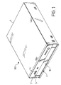
- FIGURE 1 is a perspective view showing the externals of the disc player according to the one embodiment of the present invention.
- the disc player 100 is incorporated in a vertical position, in other words the optical disc is incorporated in a vertical position into the main body of the information processing apparatus 200 such as a personal computer as shown in FIGURE 2.
- 1 denotes the cabinet
- 2 denotes a front panel.
- a disc tray entrance opening 3 for loading or ejecting a disc tray 10 loading thereon an optical disc inside and outside the cabinet 1
- an ejection button 4 for electrically commanding the disc tray loading and ejecting and a small hole 5 for annually ejecting the disc tray 10 out the cabinet 1 where a wire or the like is inserted when the automatic driving system of the disc tray 10 has failured due to some troubles.
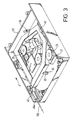
- FIGURE 3 is a perspective view showing an internal structure of the optical disc player without cabinet 1 from the underside.
- FIGURE 4 is a perspective view showing the state that the disc tray 10 is ejected outside the optical disc reproducing apparatus, as shown in FIGURE 3.
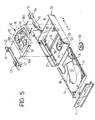
- FIGURE 5 is an exploded view of FIGURE 4.
- FIGURE 6 is a perspective view showing the internal structure of the optical disc player from the upperside.
- the cabinet 1 is omitted in the drawings.
- 20 denotes a mold plastic frame.
- 30 denotes a pickup unit (hereinafter referred to as the PU unit).
- 40, 41 denote a pair of sliders for supporting the disc tray 10 and the PU unit 30 and guiding their movement in the flame 20.
- a motor 23 for loading or ejecting the disc tray 10 into or out of the cabinet 1 is provided on both inner sides of the frame 20 .
- a linking bar 24 for installing a link 50 which serves to synchronize the sliders 40 and 41 is mounted on the frame 20 as shown in FIGURE 6 .
- a disc clamper base 25 for rotatably mounting a disc clamper 60 on the frame 20 is defined.
- a disc receiving recess 11 for receiving the optical disc (not shown) and a window 12 for exposing a portion of the information carrying surface of the optical disc placed on the disc tray 10 in the moving range of the optical pickup 31.
- slider engaging libs 13, 13 are formed along the longitudinal direction of the disc tray 10.
- the slider engaging libs 13, 13 are fit into guide grooves 42, 42 defined in each sliders 40 and 41 (see FIGURE 10). Accordingly, the disc tray 10 is supported to move in the horizontal position in the direction of the arrow X-X' by the sliders 40 and 41.
- a rack gear 14 is defined on one inside of the disc tray 10 .
- the rack gear 14 is connected with the motor 23 through a series of gears.
- a pinhole 15 is formed in the pinhole 15 .
- a positioning pin 32 formed on the PU unit 30 is firmly inserted in the pinhole 15so that the disc tray 10 and the PU unit 30 are positioned with each other in their pertinent locations.
- disc holders 71, 72 and 73 for holding the edge portion of the optical disc D placed on the disc receiving recess 11 with the disc tray 10 are mounted.
- Each disc holders 71, 72 and 73 are mounted on the disc tray 10 around axes 74, 75 and 76 in the state that they are rockable in parallel with the disc tray 10. Accordingly, the disc holders 71, 72 and 73 are rockable between the first position (shown by the solid line in the drawing) where they engage with the peripheral edge of the disc D to hold the disc D in corporation with the disc tray 10 and the second position (shown by the dotted line in the drawing) where they apart from the disc D thus releasing the holding of the disc D in corporation with the disc tray 10.
- 77, 78 and 79 are guide grooves for defining respective rocking angles of the disc holders 71, 72 and 73. Protrusions 71a, 72a and 73a of the disc holders 71, 72 and 73 are inserted in the guide grooves 77, 79 and 79.
- FIGURE 8 is an enlarged view showing the disc holder 71
- FIGURE 9 is an enlarged view showing the disc holder 73.
- the disc holder 72 has the mirror image shape with the disc holder 71.
- 91 denotes a spring member.
- the spring member 91 is comprised of a coiled portion 91a and two spring arms 91b and 91c extending from the coiled portion 91a.
- the coiled portion 91a and one spring arm 91b are engaged with hooks 93 and 92 defined on the disc tray 10, while the other spring arm 91c is engaged with the protrusion 71a (73a) of the disc holder 71 (73).
- the spring member 91 is biased to straddle the spring arms 91b and 91c.
- the disc holder 71 (73) is so biased by the spring member 91 to rock in the direction of the arrow X, in other words, to the first position to engage with the peripheral edge of the disc D.
- a receptacle 95 for fastening the disc holder in the second position (the releasing and fastening position of the disc holding) by being fastened with the disc holder fastening pin 94 formed on the disc tray 10 protrudes.
- the straddling portions of the receptacle 95 can be resiliently deformed to straddle for catching the disc holder fastening pin 94 therein.
- the receptacle 25 is combined with the disc holder fastening pin 94.
- the PU unit 30 is comprised of an optical pickup 31 for reading information from the optical information carrying surface of the optical disc, a pickup feed mechanism 33 for feeding the optical pickup 31 in the radius direction of the optical disc, a disc drive system having a turntable rotatably holding the optical disc in corporation with the disc clamper 60 and a disc motor 34, a flame 35 for integrally supporting the above described structures, and a circuit board.
- the positioning pin 22 as mentioned above is integrally mounted on the frame 35. Further, from both sides of the flame 35 guide pins 36a, 36b, 36c and 36d which are inserted through guide slits 43, 44, 45 and 46 defined in the sliders 40 and 41 are projected.
- FIGURE 10 is a perspective view showing the mutual relations among the sliders 40 and 41, the disc tray 10 and the PU unit 30.
- longitudinally elongated guide grooves 42, 42 for guiding the disc tray 10 in the direction of the arrows X-X'in corporation with the slider engaging libs 13, 13 formed on the both sides of the disc tray 10 fitting into the grooves 42, 42.
- two guide slits 43, 44 (45, 46) are defined. Then the guide pins 36a, 36b and 36c, 36d projecting from the side of the flame 35 of the PU unit 30 are inserted into the guide slits 43, 44, 45 and 46.
- Each of the guide slits 43, 44, 45 and 46 has guide channels a, b and c.
- the guide channels 43a and 43c of the guide slit 43 elongate in the horizontal direction.
- the guide channel 43b of the guide slit 43 elongates in the inclined direction to link the horizontal guide channels 43a and 43c together. That is, the guide channels, e.g., 43a through 43c are so constructed to guide the PU unit 30 up-and-down within the prescribed height range according to the sliding movements of the sliders 40 and 41 in the direction of the arrow X-X'.
- rack gears 47 and 48 are defined on the bottom ends of the sliders 40 and 41.
- the rack gears 47 and 48 are respectively engaged with gears 51 and 52 fixed on both ends of a shaft 53 of the link 50, as shown in FIGURE 6.
- the link 50 is comprised of the shaft 53 and the gears 51, 52 fixed on both ends of the shaft 53, and rotatably mounted in the prescribed position of the flame 20.
- the sliders 40 and 41 move together in synchronized relation via the link 50.
- another rack gear 49 is engaged with a gear 61 which is coupled to the motor 23 through a series of gears.
- each of the sliders 40 and 41 three protrusions 96, 97 and 98 capable of bumping against the disc holders 71, 72 and 73 to rock them toward their second positions where the disc holding is released against the bias of the spring member 91.
- the slider 41 has two protrusions 97 and 98.
- the protrusions 97, 98 are staggered their altitudes from each other, i.e., in the direction perpendicular to surface of the disc D so that the protrusion 97 may bump against its only one associated disc holder 72, while the other protrusion 98 may bump against its only one associated disc holder 73.
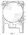
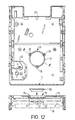
- FIGURES 5, 6 and 12 denotes a disc clamper mounting base for rotatably mounting the disc clamper 60.
- the disc clamper mounting base 25 has three hooks 26, 26, 26 for positioning the disc clamper 60 fitted in the disc clamper mounting base 25.
- the disc clamper 60 is rotatably held between the three hooks 26, 26, 26 and a pedestal 27 defined in lower part of the round opening.
- the hooks 26, 26, 26 can be resiliently deformed by being depressed by the disc clamper 60 when the disc clamper 60 is mounted into the disc clamper mounting base 25.
- each hook 26 has a tapered end for resiliently deformable by the depression from the disc clamper 60 at the mounting of the disc clamper 60, and a horizontal surface for checking the escape of the disc clamper 60 from the disc clamper mounting base 25 after the disc clamper 60 having been mounted therein.
- the disc clamper 60 has a magnet (not shown) for holding the optical disc D between the turntable 28 and the disc clamper 60 by attracting with a magnetic substance (not shown) provided on turntable 28.
- FIGURE 13 is a plan view showing the state that the disc tray 10 is ejected outside the main body.
- the disc tray loading operation is initiated by that the user pushes the disc tray 10 in the direction of the arrow X by his/her finger and the like. If the disc tray 10 is forced by a certain distance the motor 23 is turned ON. Then after that the motor 23 drives the entire of clutch gear 64 to rotate in the direction of the arrow, so that the disc tray 10 is loaded into the main body of the apparatus.
- the rear end 10a of the disc tray 10 bumps against one end 81 of a rocking lever 80, as shown in FIGURE 14.
- the rocking lever 80 is rockably suspended to the frame 20 via an axis 82.
- the other end 83 of the rocking lever is able to bump against the rear end of the slider 40 for pushing the slider 40 frontward (the direction of the arrow X).
- the rocking lever 80 is rocked in the direction of the arrow C by the end 81 of the rocking lever 80 bumping against the rear end 10a of the disc tray 10.
- the slider 40 commences to slide frontward (the direction of the arrow X).
- the other slider 41 linked with the slider 40 through the link 50 also slides frontward (the direction of the arrow X) in synchronism with the slider 40.
- FIGURE 16A is a side view showing the positional relationships among the guide pins 36a, 36b, 36c and 36d of the PU unit 30 and the guide slits 43, 44, 45 and 46 of the sliders 40 and 41 at that time.
- the dotted lines in the drawing illustrate respective positions of the guide pins 36a, 36b, 36c and 36d at the time that the disc tray 10 is ejected outside the main body of the apparatus.
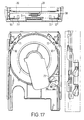
- FIGURE 17 includes flat, front and side views for showing the states of the disc holders 71, 72 and 73 at this time. As shown in the drawing, either of the disc holders 71, 72 and 73 does not bump against the protrusions 96, 97 and 98 on the sliders 40 and 41 in this time. And further, since the PU unit 30 does not yet move up-and-down, the PU unit 30 is placed in the state where it does not bump against any of the disc D and turntable 28.
- the slider 40 is placed in the position where the rack gear 49 can engage with the gear 61 in that time. Accordingly, the sliders 40 and 41 are driven furthermore in the direction of the arrow X by the motor 23. According to the movement of the sliders 40 and 41 the PU unit 30 commences to move toward the disc clamper 60.
- FIGURES 18 and 16B show the states immediately after that the protrusions 96, 97 and 98 on the sliders 40 and 41 have bumped against their associated one of the disc holders 71, 72 and 73 by the movements of the sliders 40 and 41 and PU unit 30. At this time, the turntable 28 has already bumped against the disc D and been in the process of pressing the disc D toward the disc clamper 60.
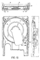
- FIGURES 19 and 16C show the states of the disc holders 71, 72 and 73 at the time that the disc tray loading has just finished.
- the disc holders 71, 72 and 73 arc rocked toward around the second position by their corresponding protrusions 96, 97 and 98.
- the second position represents the position where the disc holding state according to the disc holders 71, 72 and 73 has been released.
- the disc D on the disc tray 10 is disengaged from the disc holders 71, 72 and 73, and detached from the disc tray 10 by being pressed by the turntable 28.
- the disc D is held between the turntable 28 and the disc clamper 60.
- the disc tray 10 is ejected outside the main body of the apparatus by operating the eject button 4 on the front panel 2.
- the controller controls the motor 23 to drive in opposite direction to the loading time.
- this PU unit 30 moves from the position C (altitude position) to the position A (altitude position) in FIGURE 16, and thus the disc holding is released. After this operation, the disc tray is ejected in the entirely reverse process to the loading process.
- the disc tray apparatus can be stably used in the vertical position, as explained above, the disc tray according to the present invention can be used in the horizontal position.
- the optical disc D can be simply placed on the disc tray 10.
- the disc holders 71, 72 and 73 on the disc tray 10 are left unused. So, when the apparatus is used in the horizontal position, as shown in FIGURES 20, 8 and 9, the straddling portion of the receptacle 95 is pressed against the disc holder fastening pin 94 by manually rocking the disc holders 71, 72 and 73 in the direction of the arrow X. Then the disc holder fastening pin 94 is compelled to be fit into the straddling portion. Accordingly, the disc holders 71, 72 and 73 are fastened in the remote positions from the disc placed on the disc tray not to engage with the disc.
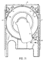
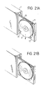
- FIGURE 21 shows the state that the disc D is placed on the disc tray 10.
- the disc is leaned forward a little and the lower edge portion of the disc D is inserted between the lowerside disc holders 72, 73 and the disc tray 10. Then by slightly pressing the disc D lowerward, the disc D is moved to one edge of the disc receiving portion (recess) 11 on the disc tray 10 with against with the elasticity of the spring member 91. That is, on the edge of the disc receiving portion (recess) 11 on the disc tray 10 as shown in FIGURE 20, a margin for shifting the disc D to one prescribed position P2 shifted by a little distance from another prescribed position P1 is provided.
- the disc D When the disc D is placed on the disc tray 10, by shifting the disc D to the position P2 the disc D can fit in the disc receiving portion (recess) 11 without engaging with-the-upper disc holder 71. After that, when the user releases the disc D from his/her finger the disc D is lifted up by the elasticity of the spring member 91 engaged with the lower disc holders 72 and 73. Then the upper part of the disc D is inserted between the disc holder 71 and the disc tray 10. As a result, the disc D is moved to the prescribed position P1 (see FIGURE 20) within the disc receiving portion (recess) 11 and stably placed therein.
- the optical disc player in the above embodiments, it is possible to easily place the disc D on the disc tray 10 by e.g., one-handed manipulation It is also possible to easily take the disc out from the disc tray 10 by, also one-handed manipulation.
- the disc tray and the disc player employing such a disc tray of the present invention as described above, when the disc tray is ejected outside the disc player, the disc placed on the disc tray is held between the disc tray and the disc holding member. Then the disc holding member is moved to the position where the disc holding is released in the course of that the disc tray is loaded to the prescribed reproducing position in the disc player, or in the course of that the disc is detached from the disc tray placed in the disc player by the disc driving mechanism.
- the apparatus Even if the apparatus is used in a vertical position, in other words, the disc is placed in a almost vertical position on the disc tray it is possible to stabilize the disc in the appropriate position of the disc tray, load the disc tray to the prescribed reproducing position within the disc player and detach the disc from the disc tray to reproduce the disc at the reproducing position.
- the present invention can provide an extremely preferable disc tray and disc player employing such disc tray.
Landscapes
- Feeding And Guiding Record Carriers (AREA)
- Holding Or Fastening Of Disk On Rotational Shaft (AREA)
Claims (8)
- Un lecteur de disque (100) susceptible de mettre en place dans le lecteur de disque et d'éjecter de celui-ci un plateau de support de disque (10) lorsque ledit lecteur de disque est disposé verticalement, et également susceptible de mettre en place dans le lecteur de disque (100) et d'éjecter de celui-ci le plateau de support de disque (10) lorsque ledit lecteur de disque (100) est disposé horizontalement, ledit lecteur de disque (100) comprenant :caractérisé en ce que l'élément de maintien de disque comprend des éléments (71, 72, 73) montés de manière sélective sur trois coins ou davantage du plateau de support de disque qui présente une forme rectangulaire ; etun élément de maintien de disque déplaçable parallèlement à une surface du plateau de support de disque (10) entre une première positon dans laquelle l'élément de maintien de disque ne maintient pas un disque sur le plateau de support de disque lorsque le disque se trouve sur le plateau de support de disque et une seconde position dans laquelle l'élément de maintien de disque maintien un disque sur le plateau de support de disque lorsque le disque se trouve sur le plateau de support de disque au moins lorsque le plateau de support de disque est placé à l'extérieur du lecteur de disque ; etdes moyens de libération de maintien de disque pour dégager l'élément de maintien de disque du disque placé sur le plateau de support de disque en frappant contre l'élément de maintien de disque lorsque le plateau de support de disque se déplace vers une position de lecture de disque prescrite dans le lecteur de disque ;
deux des éléments de maintien (72, 73) sont alignés l'un avec l'autre le long d'une direction de mise en place du plateau de support de disque (10) et les moyens de libération de maintien de disque (97, 98) qui frappent contre les deux éléments de maintien de disque associés sont décalés dans leurs positions dans une direction perpendiculaire à la surface du disque placé sur le plateau de support de disque. - Un lecteur de disque tel que revendiqué à la revendication 1, dans lequel l'élément de maintien de disque est monté de manière déplaçable sur le plateau de support de disque (10) le long d'une surface qui est parallèle à une surface du disque placé sur le plateau de support de disque (10), ledit élément de maintien de disque pouvant se déplacer entre une première position dans laquelle l'élément de maintien de disque ne maintient pas un disque sur le plateau de support de disque (10) lorsque le disque fait face au plateau de support de disque (10) et une seconde position dans laquelle l'élément de maintien de disque maintient un disque sur le plateau de support de disque (10) lorsque le disque fait face au plateau de support de disque (10), au moins lorsque le plateau de support de disque (10) est placé à l'extérieur du lecteur de disque (100).
- Un lecteur de disque tel que revendiqué à la revendication 2, dans lequel le lecteur de disque (100) comprend en outre un mécanisme d'entraínement de disque (28, 60) monté dans le lecteur de disque pour détacher un disque du plateau de support de disque mis en place dans le lecteur de disque dans la direction généralement perpendiculaire à la face du disque, et pour entraíner le disque.
- Un lecteur de disque tel que revendiqué à la revendication 3, dans lequel le mécanisme d'entraínement de disque (28, 60) entraíne le disque en maintenant le disque.
- Un lecteur de disque tel que revendiqué dans une quelconque des revendications 1 à 4, comprenant en outre un moyen de sollicitation pour solliciter l'élément de maintien de disque à se déplacer dans la position de maintien de disque.
- Un lecteur de disque tel que revendiqué dans une revendication précédente quelconque, dans lequel :ledit plateau de support de disque (10) comprend en outre une partie de réception de disque pour recevoir le disque, etdes moyens de sollicitation pour solliciter l'élément de maintien de disque vers la position de maintien.
- Un lecteur de disque tel que revendiqué dans une quelconque revendication précédente, dans lequel ledit plateau de support de disque comprend en outre :une partie de réception de disque pour recevoir le disque ;un élément d'interposition de disque défini sur un côté du plateau le long de la direction de mise en place du plateau pour interposer le bord du disque avec la partie de réception de disque ; etdes moyens de sollicitation pour solliciter l'élément de maintien de disque vers la position de maintien.
- Un lecteur de disque tel que revendiqué dans une quelconque revendication précédente comprenant en outre un moyen de fixation pour fixer l'élément de maintien de disque en une position prescrite où l'élément de maintien de disque est libérable.
Applications Claiming Priority (6)
| Application Number | Priority Date | Filing Date | Title |
|---|---|---|---|
| JP3670695 | 1995-02-24 | ||
| JP3670795 | 1995-02-24 | ||
| JP36707/95 | 1995-02-24 | ||
| JP7036706A JPH08235713A (ja) | 1995-02-24 | 1995-02-24 | ディスク再生装置 |
| JP7036707A JPH08235714A (ja) | 1995-02-24 | 1995-02-24 | ディスク用トレー |
| JP36706/95 | 1995-02-24 |
Publications (3)
| Publication Number | Publication Date |
|---|---|
| EP0729146A2 EP0729146A2 (fr) | 1996-08-28 |
| EP0729146A3 EP0729146A3 (fr) | 1997-04-23 |
| EP0729146B1 true EP0729146B1 (fr) | 2001-05-02 |
Family
ID=26375787
Family Applications (1)
| Application Number | Title | Priority Date | Filing Date |
|---|---|---|---|
| EP96301256A Expired - Lifetime EP0729146B1 (fr) | 1995-02-24 | 1996-02-26 | Plateau de support de disque et lecteur de disque utilisant ce plateau |
Country Status (3)
| Country | Link |
|---|---|
| US (1) | US5844874A (fr) |
| EP (1) | EP0729146B1 (fr) |
| DE (1) | DE69612635T2 (fr) |
Families Citing this family (24)
| Publication number | Priority date | Publication date | Assignee | Title |
|---|---|---|---|---|
| JP3510068B2 (ja) * | 1996-12-24 | 2004-03-22 | 松下電器産業株式会社 | ディスククランプ装置 |
| EP1365396B1 (fr) * | 1997-01-31 | 2006-01-11 | CLARION Co., Ltd. | Appareil pour la reproduction de disque,dispositif changeur de disque et magasin de disque |
| JP3751706B2 (ja) | 1997-03-31 | 2006-03-01 | クラリオン株式会社 | ディスク再生装置 |
| CN1080436C (zh) * | 1997-02-27 | 2002-03-06 | 源兴科技股份有限公司 | 光碟机碟片承载装置 |
| EP0862174A1 (fr) * | 1997-02-27 | 1998-09-02 | Lite-On Technology Corp. | Dispositif de changement de disque pour lecteur de disque optique |
| JP3720962B2 (ja) * | 1997-10-13 | 2005-11-30 | 株式会社東芝 | 情報処理装置 |
| JP3506597B2 (ja) * | 1998-01-30 | 2004-03-15 | 松下電器産業株式会社 | ディスク移送機構 |
| JP2000260092A (ja) * | 1999-03-05 | 2000-09-22 | Hitachi Ltd | ディスク駆動装置 |
| US6059389A (en) * | 1999-06-01 | 2000-05-09 | Hsu; Chen-Tung | Device housing for CD-ROM player and the like |
| WO2000079529A1 (fr) * | 1999-06-22 | 2000-12-28 | Mitsubishi Denki Kabushiki Kaisha | Dispositif a disques |
| EP1081695A3 (fr) * | 1999-08-27 | 2001-05-02 | Star Micronics Co., Ltd. | Dispositif de chargement de disque, appareil et procédé de montage d'un disque sur un mechanisme rotatif, et appareil rotatif d'impression |
| JP2001067761A (ja) * | 1999-08-27 | 2001-03-16 | Sony Computer Entertainment Inc | ディスク装置 |
| JP2001101821A (ja) * | 1999-09-29 | 2001-04-13 | Sony Corp | ディスクアダプター |
| JP3410997B2 (ja) * | 1999-10-06 | 2003-05-26 | 株式会社ソニー・コンピュータエンタテインメント | ディスク装置、およびディスクトレー |
| JP3406256B2 (ja) * | 1999-10-22 | 2003-05-12 | 株式会社ソニー・コンピュータエンタテインメント | ディスク装置、ディスクトレー、および案内部材 |
| JP3608490B2 (ja) * | 2000-09-19 | 2005-01-12 | 船井電機株式会社 | ディスクトレイ |
| TW529751U (en) * | 2001-06-15 | 2003-04-21 | Lite On It Corp | Matching structure of slide track and disk carrier of optical disk player |
| JP4068014B2 (ja) * | 2003-06-24 | 2008-03-26 | シャープ株式会社 | 光ディスク装置 |
| JP2006024278A (ja) * | 2004-07-08 | 2006-01-26 | Matsushita Electric Ind Co Ltd | 光ディスク装置 |
| TW200614158A (en) * | 2004-10-18 | 2006-05-01 | Benq Corp | Optical disk drive |
| DE602005026734D1 (de) * | 2004-10-22 | 2011-04-14 | Sanford Lp | Drucker |
| US20070086306A1 (en) * | 2005-10-13 | 2007-04-19 | Ip Michael C | Data reading device with a switch locatable anywhere, and related system and method |
| US7733659B2 (en) | 2006-08-18 | 2010-06-08 | Delphi Technologies, Inc. | Lightweight audio system for automotive applications and method |
| KR20140104619A (ko) * | 2013-02-20 | 2014-08-29 | 도시바삼성스토리지테크놀러지코리아 주식회사 | 광디스크 드라이브 및 광디스크 드라이브의 메인 프레임 |
Family Cites Families (7)
| Publication number | Priority date | Publication date | Assignee | Title |
|---|---|---|---|---|
| CA1228030A (fr) * | 1983-06-15 | 1987-10-13 | Petrus L.A. Rouws | Lecteur de disque comportant un mecanisme de chargement de disque et support de disque utilise dans ce lecteur |
| US4707821A (en) * | 1983-11-08 | 1987-11-17 | U.S. Philips Corporation | Disc holder for a rigid audio and/or video disc |
| JPH0325319Y2 (fr) * | 1985-07-13 | 1991-05-31 | ||
| US4773058A (en) * | 1986-10-27 | 1988-09-20 | Eastman Kodak Company | Disk handling system and apparatus |
| US5142523A (en) * | 1987-07-31 | 1992-08-25 | Yamaha Corporation | Disc playback device |
| NL8702604A (nl) * | 1987-11-02 | 1989-06-01 | Philips Nv | Platenspeler met een laadinrichting voor het laden van een op een plaatdrager aanwezige plaat. |
| JP3321851B2 (ja) * | 1992-09-25 | 2002-09-09 | ソニー株式会社 | ディスク装置 |
-
1996
- 1996-02-23 US US08/605,887 patent/US5844874A/en not_active Expired - Fee Related
- 1996-02-26 DE DE69612635T patent/DE69612635T2/de not_active Expired - Fee Related
- 1996-02-26 EP EP96301256A patent/EP0729146B1/fr not_active Expired - Lifetime
Also Published As
| Publication number | Publication date |
|---|---|
| DE69612635T2 (de) | 2001-08-09 |
| DE69612635D1 (de) | 2001-06-07 |
| EP0729146A3 (fr) | 1997-04-23 |
| US5844874A (en) | 1998-12-01 |
| EP0729146A2 (fr) | 1996-08-28 |
Similar Documents
| Publication | Publication Date | Title |
|---|---|---|
| EP0729146B1 (fr) | Plateau de support de disque et lecteur de disque utilisant ce plateau | |
| JP3131783B2 (ja) | ディスク再生装置 | |
| US4627042A (en) | Loading apparatus for a disc | |
| US4625304A (en) | Automatic loading disc player | |
| KR100262791B1 (ko) | 디스크 구동 장치용 디스크 로딩 기구 | |
| JPWO1998050918A1 (ja) | ディスクローディング装置及びディスクのアダプタ | |
| US6661766B2 (en) | Disk apparatus and disk magazine with upper and lower sections | |
| JP3933080B2 (ja) | ディスク装置 | |
| JPH03235259A (ja) | 複数ディスク収納プレーヤ | |
| US5943309A (en) | Disk unit having a slide-restricting member for easy disk-exchanging operation | |
| JP3550958B2 (ja) | ディスク装置 | |
| JP3890660B2 (ja) | ディスク記録及び/又は再生装置 | |
| JP3890661B2 (ja) | ディスク記録及び/又は再生装置 | |
| JP2002157809A (ja) | ディスクカートリッジ並びにディスクの記録及び/又は再生装置 | |
| US5796709A (en) | Disk reproducting apparatus having improved connection between the centering member and turntable | |
| US20060143625A1 (en) | Optical disc device and tray lock mechanism thereof | |
| JPH08235713A (ja) | ディスク再生装置 | |
| JP3757532B2 (ja) | ディスク記録及び/又は再生装置 | |
| JP3039274B2 (ja) | クランプ機構 | |
| JPH08235714A (ja) | ディスク用トレー | |
| JPH09251692A (ja) | ディスク用トレーとディスク再生装置 | |
| JP3890659B2 (ja) | ディスク記録及び/又は再生装置 | |
| JPH08106694A (ja) | クラッチギア及びディスク再生装置 | |
| JPH09259500A (ja) | ディスク装填装置 | |
| JPH09245406A (ja) | ディスク用トレーとディスク再生装置 |
Legal Events
| Date | Code | Title | Description |
|---|---|---|---|
| PUAI | Public reference made under article 153(3) epc to a published international application that has entered the european phase |
Free format text: ORIGINAL CODE: 0009012 |
|
| 17P | Request for examination filed |
Effective date: 19960319 |
|
| AK | Designated contracting states |
Kind code of ref document: A2 Designated state(s): DE GB |
|
| PUAL | Search report despatched |
Free format text: ORIGINAL CODE: 0009013 |
|
| AK | Designated contracting states |
Kind code of ref document: A3 Designated state(s): DE GB |
|
| 17Q | First examination report despatched |
Effective date: 19990506 |
|
| GRAG | Despatch of communication of intention to grant |
Free format text: ORIGINAL CODE: EPIDOS AGRA |
|
| GRAG | Despatch of communication of intention to grant |
Free format text: ORIGINAL CODE: EPIDOS AGRA |
|
| GRAH | Despatch of communication of intention to grant a patent |
Free format text: ORIGINAL CODE: EPIDOS IGRA |
|
| GRAH | Despatch of communication of intention to grant a patent |
Free format text: ORIGINAL CODE: EPIDOS IGRA |
|
| GRAA | (expected) grant |
Free format text: ORIGINAL CODE: 0009210 |
|
| AK | Designated contracting states |
Kind code of ref document: B1 Designated state(s): DE GB |
|
| REF | Corresponds to: |
Ref document number: 69612635 Country of ref document: DE Date of ref document: 20010607 |
|
| REG | Reference to a national code |
Ref country code: GB Ref legal event code: IF02 |
|
| PLBE | No opposition filed within time limit |
Free format text: ORIGINAL CODE: 0009261 |
|
| STAA | Information on the status of an ep patent application or granted ep patent |
Free format text: STATUS: NO OPPOSITION FILED WITHIN TIME LIMIT |
|
| 26N | No opposition filed | ||
| PGFP | Annual fee paid to national office [announced via postgrant information from national office to epo] |
Ref country code: DE Payment date: 20090219 Year of fee payment: 14 |
|
| PGFP | Annual fee paid to national office [announced via postgrant information from national office to epo] |
Ref country code: GB Payment date: 20090225 Year of fee payment: 14 |
|
| GBPC | Gb: european patent ceased through non-payment of renewal fee |
Effective date: 20100226 |
|
| PG25 | Lapsed in a contracting state [announced via postgrant information from national office to epo] |
Ref country code: DE Free format text: LAPSE BECAUSE OF NON-PAYMENT OF DUE FEES Effective date: 20100901 |
|
| PG25 | Lapsed in a contracting state [announced via postgrant information from national office to epo] |
Ref country code: GB Free format text: LAPSE BECAUSE OF NON-PAYMENT OF DUE FEES Effective date: 20100226 |