EP0729199A2 - Composant électrique - Google Patents
Composant électrique Download PDFInfo
- Publication number
- EP0729199A2 EP0729199A2 EP96100470A EP96100470A EP0729199A2 EP 0729199 A2 EP0729199 A2 EP 0729199A2 EP 96100470 A EP96100470 A EP 96100470A EP 96100470 A EP96100470 A EP 96100470A EP 0729199 A2 EP0729199 A2 EP 0729199A2
- Authority
- EP
- European Patent Office
- Prior art keywords
- housing
- flat cable
- electrical
- component
- connection device
- Prior art date
- Legal status (The legal status is an assumption and is not a legal conclusion. Google has not performed a legal analysis and makes no representation as to the accuracy of the status listed.)
- Withdrawn
Links
Images
Classifications
-
- H—ELECTRICITY
- H01—ELECTRIC ELEMENTS
- H01R—ELECTRICALLY-CONDUCTIVE CONNECTIONS; STRUCTURAL ASSOCIATIONS OF A PLURALITY OF MUTUALLY-INSULATED ELECTRICAL CONNECTING ELEMENTS; COUPLING DEVICES; CURRENT COLLECTORS
- H01R12/00—Structural associations of a plurality of mutually-insulated electrical connecting elements, specially adapted for printed circuits, e.g. printed circuit boards [PCB], flat or ribbon cables, or like generally planar structures, e.g. terminal strips, terminal blocks; Coupling devices specially adapted for printed circuits, flat or ribbon cables, or like generally planar structures; Terminals specially adapted for contact with, or insertion into, printed circuits, flat or ribbon cables, or like generally planar structures
- H01R12/50—Fixed connections
- H01R12/59—Fixed connections for flexible printed circuits, flat or ribbon cables or like structures
- H01R12/65—Fixed connections for flexible printed circuits, flat or ribbon cables or like structures characterised by the terminal
- H01R12/67—Fixed connections for flexible printed circuits, flat or ribbon cables or like structures characterised by the terminal insulation penetrating terminals
- H01R12/675—Fixed connections for flexible printed circuits, flat or ribbon cables or like structures characterised by the terminal insulation penetrating terminals with contacts having at least a slotted plate for penetration of cable insulation, e.g. insulation displacement contacts for round conductor flat cables
Definitions
- the invention relates to an electrical component for connection to current-carrying electrical lines, in particular to flat cables with at least two electrical conductors running next to one another in one plane, a connection device for contacting the electrical conductors via contact elements being provided and the flat cable having asymmetrical cross-sectional configurations, which have corresponding cross-sectional shapes of the connection device interact when making contact and have the electrical conductor of the flat cable ready for a defined contact.
- the connecting device has a number of connecting terminals for branching conductors corresponding to the number of wires of the flat cable.
- the terminals themselves each have a contact screw with a tip for piercing the insulation of the flat cable.
- the flat cable used in this device has at least one asymmetrically arranged longitudinal groove on at least one of its flat sides, while the connecting device has a receiving space adapted to the cross-sectional shape of the flat cable. This receiving space has at least one projection, which is intended to engage in the longitudinal groove of the flat cable.
- the advantage of this device is that the insertion of the flat cable into the receiving space of the connection device can only take place in such a position that each contact screw of the connection terminal can only ever be brought into contact with a single, predetermined wire of the flat cable.
- a holder for installation devices in cable ducts which is equipped with fastening elements for fixing the installation devices on the bottom areas of the cable ducts.
- These fastening elements are U-shaped snap-on brackets with latching legs projecting outwards, which engage behind latching elements molded onto the installation device.
- the actual mounting takes place via a base plate equipped with locking elements directed towards the snap-on holder of the channel bottom, which has snap-in openings on its longitudinal edges for locking hooks correspondingly formed on the underside of the installation device.
- spacers are also formed on the bottom of the installation device near the edge, which support the installation device in the latched state on the assigned floor areas of the base plate.
- the combination of the installation device with the base plate is then based on e.g. U-shaped fastening elements snapped onto the bottom areas of the cable ducts. This means that the installation device can be fastened to the bottom of the cable duct with two clicks. The installation devices fastened in this way can then be supplied with current via the electrical lines laid in the cable ducts via the usual connection devices.
- connection device is integrated as a housing in the electrical component, that the opening of the connection device can be closed by a cover part, which on the one hand has old latching elements for latching with detents of the connection device and on the other hand with continuous holding webs for holding Backing of molded lugs on a base plate is equipped that an axially continuous groove opening for receiving the flat cable is formed in the base plate, and that the connecting lines for the electrical component and the line wires of the flat cable can be electrically conductively connected to one another in the housing of the connecting device.
- the housing of the connection device is connected in one piece to the housing of the electrical component. In this way, an assembly process when connecting the connection device to the electrical component is avoided.
- the housing of the connection device is fixed to the housing of the electrical component via mechanical connecting means or by means of catches. It is essential here that the housing of the connection device is firmly connected to the housing of the electrical component.
- the axially continuous groove opening in the bed plate and the underside of the housing of the connecting device form an elongated through channel for the flat cable, which is held immovably in the through channel with the latching of the cover part on the connecting device and the bottom plate. This immovability makes it easier to contact the flat cable's electrical conductors.
- a further advantage of the invention is seen in the fact that an opening is made in the cover part for receiving a component which can be rotated through 180 °, which in turn has a through opening for the variable contacting of the electrical conductors of the flat cable via a tapping screw inserted into the through opening.
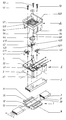
- the flat cable 2 is inserted into the groove 11 of the base plate 1.
- the flat cable 2 consists of the five conductors PE, L1, L2, L3 and N as well as an insulating sheath.
- the flat cable 2 is equipped on its underside with asymmetrical projections 21, 22 which engage in corresponding groove openings 12, 13 on the bottom 11 of the base plate 1. Through these grooves 12, 13 and the projections 21, 22, the mounting direction of the flat cable 2 is predetermined in the base plate.
- connection device 4 is brought over the base plate 1 and fixed on the base plate 1.
- the housing 3 of the connection device 4 is firmly connected to the electrical component 6, which is only indicated in the drawing.
- the housing 3 has axially extending hooks 31 which, when assembled, engage projections 14, 15 on the base plate 1 and thus fix the housing 3 on the base plate 1 so that they are safe to install.
- the connecting device 4 consists of the wiring elements PE, L, N and their mounting brackets in the housing 3.
- the mounting brackets consist of the insulation displacement terminals 41, 42, which are provided for contacting the lines PE and N.
- the self-tapping screws 51, 52 reach through the cover part 5 and the through openings 511, 521 provided in the cover part 5 during assembly.
- the insulation displacement connector 43 has the through openings 431, 432, 433, which can be controlled in detail as required by the component 44 with the through opening 441 which can be rotated through 180 °.
- the openings 411, 421, 431, 432, 433 in the insulation displacement clamps 41, 42, 43 are threaded openings for the threaded screws 51, 52, 53, the threaded screw 53 being inserted in the rotatable component 44 via the through-hole 441.
- the lines PE, L2 and N of the flat cable 2 are contacted via the threaded screws 51, 52, 53. Since the insulation displacement terminals 41, 42, 43 are connected in a metallically conductive manner to the threaded screws 51, 52, 53, the connection lines PE, L2 and N are simultaneously made by contacting the self-tapping screws 51, 52, 53 with the conductors PE, L2 and N of the flat cable powered for the electrical component.
- the electrical line L1, L2 or L3 can be controlled by rotating the rotatable component 44.
- the cover part 5 is fixed on the housing 3 and this housing 3 above the flat cable 2 on the base plate 1, the flat cable 2 being clamped and immovably held in its seat in the groove 11 of the base plate 1.
- the rotatable component 44 is already inserted into the receiving opening 57 of the cover part.
- stops are provided in the receiving opening 57 as well as in the rotatable component 44, in the region of which the component 44 can be rotated.
- the individual electrical conductors - in the example PE, L2, N - are contacted after the rotatable component 44 has been installed in the receiving opening 57 and after the snap-in connection of the individual components of the cover part 5, housing 3 and base plate 1 with a flat cable 2.
Landscapes
- Multi-Conductor Connections (AREA)
- Coupling Device And Connection With Printed Circuit (AREA)
- Organic Insulating Materials (AREA)
- Transition And Organic Metals Composition Catalysts For Addition Polymerization (AREA)
- Glass Compositions (AREA)
Applications Claiming Priority (2)
| Application Number | Priority Date | Filing Date | Title |
|---|---|---|---|
| DE29503158U | 1995-02-24 | ||
| DE29503158U DE29503158U1 (de) | 1995-02-24 | 1995-02-24 | Elektrisches Bauteil |
Publications (2)
| Publication Number | Publication Date |
|---|---|
| EP0729199A2 true EP0729199A2 (fr) | 1996-08-28 |
| EP0729199A3 EP0729199A3 (fr) | 1997-06-11 |
Family
ID=8004466
Family Applications (1)
| Application Number | Title | Priority Date | Filing Date |
|---|---|---|---|
| EP96100470A Withdrawn EP0729199A3 (fr) | 1995-02-24 | 1996-01-15 | Composant électrique |
Country Status (5)
| Country | Link |
|---|---|
| EP (1) | EP0729199A3 (fr) |
| CZ (1) | CZ287137B6 (fr) |
| DE (1) | DE29503158U1 (fr) |
| PL (1) | PL180067B1 (fr) |
| RU (1) | RU2118021C1 (fr) |
Families Citing this family (3)
| Publication number | Priority date | Publication date | Assignee | Title |
|---|---|---|---|---|
| DE19958212C2 (de) * | 1999-12-02 | 2003-08-07 | Raymond A & Cie | Vorrichtung zum Festlegen eines Flachbandkabels |
| JP5690538B2 (ja) * | 2010-09-28 | 2015-03-25 | 矢崎総業株式会社 | 繊維導体の接続構造 |
| FR2989524B1 (fr) * | 2012-04-17 | 2015-05-22 | Souriau | Systeme de connexion monovoie rapide |
Family Cites Families (14)
| Publication number | Priority date | Publication date | Assignee | Title |
|---|---|---|---|---|
| DE6900393U (de) * | 1969-01-06 | 1969-06-12 | Altromin Gmbh Spezialfutter Gr | Verbindungsstueck fuer im winkel zueinander stehender kanaele |
| CH523579A (de) * | 1971-03-31 | 1972-05-31 | Oskar Woertz Inh H & O | Elektrische Installationseinrichtung mit einem Flachkabel und mindestens einer zugehörigen Anschlussvorrichtung |
| SU481091A1 (ru) * | 1971-08-23 | 1975-08-15 | Предприятие П/Я Г-4086 | Электрический соединитель проводников |
| US4006957A (en) * | 1974-09-25 | 1977-02-08 | Thomas & Betts Corporation | Connector |
| US4508399A (en) * | 1984-01-03 | 1985-04-02 | Amp Incorporated | Polarized ribbon cable connector having circuit components therein |
| SU1282242A1 (ru) * | 1985-01-09 | 1987-01-07 | Предприятие П/Я Г-4126 | Устройство дл соединени фланцев отрезков волноводов |
| JPH0821438B2 (ja) * | 1987-03-18 | 1996-03-04 | 住友電気工業株式会社 | 多重伝送用タ−ミナル |
| DE3833032A1 (de) * | 1988-09-29 | 1990-04-05 | Quante Fernmeldetechnik Gmbh | Anschlussdose fuer fernsprech-apparate und/oder fernsprech-zusatzgeraete |
| FR2643512B1 (fr) | 1989-02-21 | 1991-06-07 | Socapex Amphenol | Ensemble de raccordement entre un faisceau multiconducteur commun et un faisceau multiconducteur de derivation |
| DE3933942A1 (de) * | 1989-10-11 | 1991-04-18 | Pfaff Ag G M | Einrichtung zum elektrischen verbinden von mindestens einem verbraucher und einem mehradrigen kabel |
| FR2665803B1 (fr) * | 1990-08-09 | 1993-06-18 | Labinal | Connecteur de derivation. |
| US5338220A (en) * | 1992-05-19 | 1994-08-16 | The Whitaker Corporation | Electrical connector housing assembly and an electrical terminal therefor |
| DE4320327C1 (de) * | 1993-04-13 | 1994-06-01 | Siemens Ag | Aktuatoren oder Sensoren zum Anschluß an eine Busleitung |
| WO1994024728A1 (fr) * | 1993-04-14 | 1994-10-27 | Siemens Aktiengesellschaft | Connecteur a encliqueter pour conducteurs electriques |
-
1995
- 1995-02-24 DE DE29503158U patent/DE29503158U1/de not_active Expired - Lifetime
-
1996
- 1996-01-15 EP EP96100470A patent/EP0729199A3/fr not_active Withdrawn
- 1996-02-05 CZ CZ1996332A patent/CZ287137B6/cs not_active IP Right Cessation
- 1996-02-22 PL PL31289696A patent/PL180067B1/pl unknown
- 1996-02-23 RU RU96103635A patent/RU2118021C1/ru active
Also Published As
| Publication number | Publication date |
|---|---|
| PL180067B1 (pl) | 2000-12-29 |
| CZ33296A3 (en) | 1996-10-16 |
| CZ287137B6 (en) | 2000-09-13 |
| RU2118021C1 (ru) | 1998-08-20 |
| EP0729199A3 (fr) | 1997-06-11 |
| DE29503158U1 (de) | 1995-04-20 |
| PL312896A1 (en) | 1996-09-02 |
Similar Documents
| Publication | Publication Date | Title |
|---|---|---|
| EP2255410B1 (fr) | Barrette a bornes ou bloc de barrettes a bornes | |
| EP1096606B1 (fr) | Borne de connexion | |
| EP0754357B1 (fr) | Systeme de connexion pour conducteurs electriques | |
| WO2009112263A1 (fr) | Pont de commutation et unité composée d'au moins deux blocs de jonction électriques et d'un pont de commutation | |
| DE102010032383A1 (de) | Stromschienenverbinder und Stromschienensystem mit mindestens zwei benachbarten Stromschienen und einem Stromschienenverbinder | |
| EP1811604A2 (fr) | Barette à bornes électriques | |
| DE19603960B4 (de) | Mehrpoliger Abzweig-Steckverbinder | |
| EP0379662B1 (fr) | Boîtier de prises | |
| EP0337332B1 (fr) | Prise électrique de sécurité | |
| DE19746085C2 (de) | Schalterverbindungsanordnung | |
| DE10236398B3 (de) | Anschlusssystem | |
| DE4018978A1 (de) | Schiebeschalter | |
| EP0729199A2 (fr) | Composant électrique | |
| EP0542057B1 (fr) | Support pour le moteur électrique d'une machine de cuisine, en particulier presse-citrons | |
| EP0618647B1 (fr) | Boítier des prises de courant | |
| EP3590153B1 (fr) | Agencement de barettes à borne | |
| EP1296431A2 (fr) | Ensemble de barres de distribution | |
| EP1102291A2 (fr) | Interrupteur d'installation électrique ainsi que composant et source lumineuse pour un interrupteur d'installation électrique | |
| WO2009010111A1 (fr) | Distributeur de courant | |
| EP1616371B1 (fr) | Barrette de connexion pour un ensemble de bornes destine a un petit distributeur et/ou un tableau de distribution d'une installation de distribution electrique basse tension | |
| DE102013112448A1 (de) | Elektrischer Schneidklemmverbinder | |
| DE2528487A1 (de) | Schraubenlose klemmverbindung | |
| EP3761465B1 (fr) | Pièce de raccordement à fonctions auxiliaires intégrées | |
| EP0589307B1 (fr) | Support pour appareils comportant un rail avec fixation mécanique et contact électrique integral | |
| EP0697751A1 (fr) | Boîte de dérivation |
Legal Events
| Date | Code | Title | Description |
|---|---|---|---|
| PUAI | Public reference made under article 153(3) epc to a published international application that has entered the european phase |
Free format text: ORIGINAL CODE: 0009012 |
|
| AK | Designated contracting states |
Kind code of ref document: A2 Designated state(s): AT BE CH DE DK ES FR GB IE IT LI NL PT SE |
|
| 17P | Request for examination filed |
Effective date: 19961028 |
|
| PUAL | Search report despatched |
Free format text: ORIGINAL CODE: 0009013 |
|
| AK | Designated contracting states |
Kind code of ref document: A3 Designated state(s): AT BE CH DE DK ES FR GB IE IT LI NL PT SE |
|
| 17Q | First examination report despatched |
Effective date: 20000218 |
|
| STAA | Information on the status of an ep patent application or granted ep patent |
Free format text: STATUS: THE APPLICATION IS DEEMED TO BE WITHDRAWN |
|
| 18D | Application deemed to be withdrawn |
Effective date: 20020529 |