EP0729205A2 - Steckverbinderhaltevorrichtung - Google Patents
Steckverbinderhaltevorrichtung Download PDFInfo
- Publication number
- EP0729205A2 EP0729205A2 EP96301263A EP96301263A EP0729205A2 EP 0729205 A2 EP0729205 A2 EP 0729205A2 EP 96301263 A EP96301263 A EP 96301263A EP 96301263 A EP96301263 A EP 96301263A EP 0729205 A2 EP0729205 A2 EP 0729205A2
- Authority
- EP
- European Patent Office
- Prior art keywords
- connector
- terminal
- holding device
- face
- connector holding
- Prior art date
- Legal status (The legal status is an assumption and is not a legal conclusion. Google has not performed a legal analysis and makes no representation as to the accuracy of the status listed.)
- Granted
Links
- 238000003780 insertion Methods 0.000 claims abstract description 45
- 230000037431 insertion Effects 0.000 claims abstract description 45
- 230000014759 maintenance of location Effects 0.000 claims description 8
- 238000010276 construction Methods 0.000 abstract description 3
- 238000005192 partition Methods 0.000 description 5
- 238000000034 method Methods 0.000 description 4
- 230000002093 peripheral effect Effects 0.000 description 4
- 238000012966 insertion method Methods 0.000 description 3
- 238000013459 approach Methods 0.000 description 1
- 230000002265 prevention Effects 0.000 description 1
Images


Classifications
-
- H—ELECTRICITY
- H01—ELECTRIC ELEMENTS
- H01R—ELECTRICALLY-CONDUCTIVE CONNECTIONS; STRUCTURAL ASSOCIATIONS OF A PLURALITY OF MUTUALLY-INSULATED ELECTRICAL CONNECTING ELEMENTS; COUPLING DEVICES; CURRENT COLLECTORS
- H01R13/00—Details of coupling devices of the kinds covered by groups H01R12/70 or H01R24/00 - H01R33/00
- H01R13/40—Securing contact members in or to a base or case; Insulating of contact members
- H01R13/42—Securing in a demountable manner
- H01R13/436—Securing a plurality of contact members by one locking piece or operation
- H01R13/4361—Insertion of locking piece perpendicular to direction of contact insertion
-
- H—ELECTRICITY
- H01—ELECTRIC ELEMENTS
- H01R—ELECTRICALLY-CONDUCTIVE CONNECTIONS; STRUCTURAL ASSOCIATIONS OF A PLURALITY OF MUTUALLY-INSULATED ELECTRICAL CONNECTING ELEMENTS; COUPLING DEVICES; CURRENT COLLECTORS
- H01R43/00—Apparatus or processes specially adapted for manufacturing, assembling, maintaining, or repairing of line connectors or current collectors or for joining electric conductors
- H01R43/20—Apparatus or processes specially adapted for manufacturing, assembling, maintaining, or repairing of line connectors or current collectors or for joining electric conductors for assembling or disassembling contact members with insulating base, case or sleeve
-
- Y—GENERAL TAGGING OF NEW TECHNOLOGICAL DEVELOPMENTS; GENERAL TAGGING OF CROSS-SECTIONAL TECHNOLOGIES SPANNING OVER SEVERAL SECTIONS OF THE IPC; TECHNICAL SUBJECTS COVERED BY FORMER USPC CROSS-REFERENCE ART COLLECTIONS [XRACs] AND DIGESTS
- Y10—TECHNICAL SUBJECTS COVERED BY FORMER USPC
- Y10T—TECHNICAL SUBJECTS COVERED BY FORMER US CLASSIFICATION
- Y10T29/00—Metal working
- Y10T29/51—Plural diverse manufacturing apparatus including means for metal shaping or assembling
- Y10T29/5193—Electrical connector or terminal
-
- Y—GENERAL TAGGING OF NEW TECHNOLOGICAL DEVELOPMENTS; GENERAL TAGGING OF CROSS-SECTIONAL TECHNOLOGIES SPANNING OVER SEVERAL SECTIONS OF THE IPC; TECHNICAL SUBJECTS COVERED BY FORMER USPC CROSS-REFERENCE ART COLLECTIONS [XRACs] AND DIGESTS
- Y10—TECHNICAL SUBJECTS COVERED BY FORMER USPC
- Y10T—TECHNICAL SUBJECTS COVERED BY FORMER US CLASSIFICATION
- Y10T29/00—Metal working
- Y10T29/53—Means to assemble or disassemble
- Y10T29/5313—Means to assemble electrical device
- Y10T29/532—Conductor
- Y10T29/53209—Terminal or connector
- Y10T29/53213—Assembled to wire-type conductor
-
- Y—GENERAL TAGGING OF NEW TECHNOLOGICAL DEVELOPMENTS; GENERAL TAGGING OF CROSS-SECTIONAL TECHNOLOGIES SPANNING OVER SEVERAL SECTIONS OF THE IPC; TECHNICAL SUBJECTS COVERED BY FORMER USPC CROSS-REFERENCE ART COLLECTIONS [XRACs] AND DIGESTS
- Y10—TECHNICAL SUBJECTS COVERED BY FORMER USPC
- Y10T—TECHNICAL SUBJECTS COVERED BY FORMER US CLASSIFICATION
- Y10T29/00—Metal working
- Y10T29/53—Means to assemble or disassemble
- Y10T29/5313—Means to assemble electrical device
- Y10T29/53265—Means to assemble electrical device with work-holder for assembly
Definitions
- the present invention relates to a connector holding device for holding a connector when a terminal is to be inserted into the connector and, more particularly, to a connector holding device for holding a connector having a terminal insertion opening formed on a rear end face thereof and a retainer attachment opening formed on an upper or lower face thereof for attachment of a retainer for preventing terminal withdrawal.
- a connector is attached to an end of a wire harness.
- the connector ensures and facilitates the connection of the wire harness with another wire harness or an electrical component.
- a plurality of terminals are respectively crimped at ends of a plurality of leads included in the wire harness, and inserted into corresponding terminal chambers of the connector.
- Such a process is partially performed by an automated apparatus, in which a movable handle holds a predetermined portion of a terminal to convey the terminal to a corresponding terminal insertion opening, and forcibly inserts the terminal into a corresponding terminal chamber through the terminal insertion opening.
- the connector may have a retainer for preventing the inserted terminal from being withdrawn therefrom.
- retainers There are two types of retainers. One is to be attached onto a face formed with the terminal insertion opening (a rear end face of the connector), and the other is to be attached onto any of the other faces of the connector (e.g., the upper face of the connector).
- the retainer of the former type is received by a cut step portion formed on part of the periphery of the terminal insertion opening. The cut step portion produces a step on the ceiling of the terminal chamber of the connector having the retainer of this type. This makes it difficult to insert the terminal into the terminal chamber because the leading end of the terminal abuts against the step.
- a terminal insertion method is proposed in Japanese Unexamined Patent Publication No.6-52962 (1994).
- a guide wall movable by means of an air cylinder is engaged with the cut step portion with the retainer being opened.
- the guide wall covers the cut step portion which interferes with the insertion of the terminal, and defines a rectangular opening smoothly extending to the terminal chamber without producing a step. This allows the terminal to be smoothly guided from the opening to the terminal chamber.
- the connector of this type is formed with a retainer attachment opening for attachment of the retainer on the upper or lower face thereof.
- the retainer attachment opening communicates with the inside of a terminal chamber.
- the retainer attachment opening may interfere with the insertion of the terminal. More specifically, the leading end of the terminal is liable to project from the retainer attachment opening or to abut against the peripheral portion defining the retainer attachment opening. This may cause the deformation of the terminal, thereby preventing the terminal from being assuredly inserted into the terminal chamber.
- a connector holding device includes terminal insertion guide means provided in association with a connector retention space.
- the terminal insertion guide means corrects the insertion direction to prevent the terminal from projecting from the opening, and guides the terminal to a predetermined direction.
- the terminal insertion guide means includes a guide face.
- the guide face is a face inclined along the terminal insertion direction. Therefore, the inserted terminal is guided to the predetermined insertion direction by the inclined face.
- the terminal insertion guide means includes connector positioning means.
- the positioning means allows the connector to be positioned in a predetermined position in the connector retention space. Since the positioning means is provided in the terminal insertion guide means, an engagement position of the terminal insertion guide means is not offset with respect to the connector positioned by the positioning means.
- the connector holding device A is adapted to hold a connector C of a particular type into which a terminal is to be inserted.
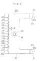
- the connector holding device A includes a base 10, upper and lower support members 11 and 12 projecting from the base 10, a pair of side support members 13 connecting side portions of the upper and lower support members 11 and 12, a pivot member 20 pivotally connected to the lower support member 12 and pivotal about a predetermined pivot center, and a coil spring 30 serving as a biasing member for constantly biasing the pivot member 20 toward the connector C.
- the upper support member 11, the lower support member 12 and the side support members 13 cooperatively define a connector holding portion 14 for holding the connector C.
- the connector holding portion 14 is adapted to hold the connector C in such a manner that a rear end face (i.e., a face formed with terminal insertion openings 41) of the connector C is exposed (see Fig. 2).
- the lower support member 12 has a recess 12a formed in a predetermined position thereof and a through-hole 12b formed coaxially with the recess 12a and communicating with the recess 12a.
- Fig. 1 which illustrates a section of the connector holding device A
- a plurality of connector holding portions each comprised of an upper support member 11, lower support member 12 and side support members 13 are aligned perpendicular to the plane of the drawing. Therefore, the connector holding device A can hold a plurality of connectors C.
- Fig. 2 is a perspective view illustrating the connector C.
- the connector C has a plurality of terminal insertion openings 41 formed on the rear end face 40 thereof and a plurality of terminal chambers 42 communicating with the terminal openings 41 for accommodating terminals T.
- the terminal chambers 42 are separated from each other by partition walls 42a, and each adapted to receive a single terminal T.
- terminals T are accommodated only in terminal chambers 42 at a lower position of the connector C. Therefore, the pivot member 20 is connected only to the lower support member 12 as shown in Fig. 1. Where terminals T are to be accommodated in terminal chambers 42 at upper and lower positions of the connector C, a pair of pivot members 20 are respectively connected to the upper and lower support members 11 and 12. In this case, the pair of pivot members 20 are disposed as facing to each other.
- a reference numeral 50 denotes retainers.
- the retainers 50 serve to prevent the terminal T accommodated in the terminal chamber 42 from being withdrawn from the connector C.
- the retainers 50 are respectively connected to an upper face 43 and a lower face 44 of the connector C via connection bands 51.
- the retainers 50 each have a plurality of engagement projections not shown.
- a plurality of retainer attachment openings 45 for attachment of the retainers 50 are formed in the upper face 43 and the lower face 44 of the connector C.
- the retainer attachment openings 45 each communicate with the corresponding terminal chamber 42. More specifically, when the retainers 50 are attached to the connector C from the outer sides thereof, the engagement projections of the retainers 50 are fitted through the retainer attachment openings 45 to engage with the respective terminals T accommodated in the terminal chambers 42, thereby preventing the withdrawal of the terminals T.
- Fig. 2 shows a state where the retainer 50 of the lower side is attached onto the lower face 44 of the connector C.
- Fig. 3 is a side view illustrating a pivot member 20
- Fig. 4 is a plan view of the pivot member as viewed from a side indicated by an arrow I in Fig. 3. Referring to Figs. 1 to 3, the pivot member 20 will be described in detail.
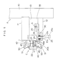
- the pivot member 20 is supported pivotally around a shaft S by a support frame 15 projecting from the lower support member 12. More specifically, the pivot member 20 can assume either a first attitude which allows parts of the pivot member 20 to enter the retainer attachment openings 45 or a second attitude which allows the parts of the pivot member 20 to be retracted from the retainer attachment openings 45 (see Fig. 5) in a state where the connector C is held in the connector holding portion 14.
- the pivot member 20 has an indented thin portion 20c formed besides proximal end portions 20a and a distal end portion 20b thereof.
- the proximal end portions 20a of the pivot member 20 are formed with respective bosses 21.
- the shaft S is inserted into openings 21a respectively formed in the bosses 21, and a center axis of the shaft S serves as a pivot axis of the pivot member 20.
- the pivot member 20 has a pair of proximal end portions 20a as shown in the plan view of the pivot member 20 of Fig. 4.
- the distal end portion 20b of the pivot member 20 is tapered (see Fig. 3).
- the distal end portion 20b has an inclined face 22 which rises from the edge thereof to the rear side, and an abutting face 24 which is to abut against peripheral portions of the retainer attachment openings 45 when the distal end portion 20b is engaged with the retainer attachment openings 45.
- a plurality of through-grooves 23 are formed along a ridge of the tapered portion, i.e., in a portion 22a defined by the inclined face 22 and the abutting face 24.
- the through-grooves 23 extend across the portion 22a from the inclined face 22 to the abutting face 24.
- the through-grooves 23 are aligned across the width of the pivot member 20 (see Fig. 4).
- the pitch between two adjacent through-grooves 23 corresponds to the pitch between two adjacent partition walls 45a separating the retainer attachment openings 45 (see Fig. 2).
- the width W of each through-groove 23 corresponds to the thickness of each partition wall 45a.
- a lever 25 for pivoting the pivot member 20 is attached to a generally middle portion of the pivot member 20. More specifically, a threaded hole 26 is formed in the generally middle portion of the pivot member 20, and a male screw portion is formed at an end of the lever 25. The lever 25 is threadedly attached to the pivot member 20 by screwing the male screw portion of the lever 25 into the threaded hole 26. A grip 25a is formed at a distal end of the lever 25 for easy hand gripping.
- the coil spring 30 is provided between the lower support member 12 and the pivot member 20.
- the coil spring 30 is fitted in the recess 12a of the lower support member 12, which serves as a seat for the coil spring 30.
- the lever 25 extends through the through-hole 12b of the lower support member 12 and the coil spring 30.
- the pivot member 20 is constantly urged resiliently toward the connector C by the coil spring 30.
- the connector holding device A having a construction as described above operates as follows.
- the connector C is inserted into the connector holding portion 14 with the front end thereof facing opposite the connector holding portion 14.
- the front end of the connector C is moved in a sliding contact with the inclined face 22 in a direction indicated by a white arrow, while abutting against the pivot member 20 to depress the distal end portion 20b thereof.
- the distal end portion 20b of the pivot member 20 is inserted between the lower face 44 of the connector C and the lower retainer 50.
- the pivot member 20 biased by the coil spring 30 rotates toward the connector C.
- the partition walls 45a separating the retainer attachment openings 45 are respectively fitted into the corresponding through-grooves 23 of the pivot member 20, and the distal end portion 20b of the pivot member 20 enters the retainer attachment openings 45.
- the terminal T is inserted from the terminal insertion opening 41 (see Fig. 2) and accommodated in the terminal chamber 42.
- the terminal T If the terminal T is liable to deviate outward and project from the retainer insertion opening 45 during the insertion of the terminal T, the terminal T abuts against the inclined face 22 of the pivot member 20. Therefore, the terminal T is moved along the inclined face 22 by forcibly inserting the terminal T into the terminal chamber 42. That is, the inclined face 22 corrects the insertion path of the terminal T, thereby allowing the terminal T to be inserted into the inner-most region of the terminal chamber 42.
- the inclined face 22 of the pivot member 20 corrects the insertion path of the terminal T. Therefore, the terminal T can be assuredly inserted into the inner-most region of the terminal chamber 42 without projecting from the retainer attachment opening 45 or abutting against the peripheral surface 45b of the retainer attachment opening 45. Since the inclined face 22 formed on the pivot member 20 serves as a means for correcting the insertion path of the terminal T, the construction of the connector holding device A can be simplified, thereby reducing the cost of the device.
- the connector C can be readily taken out by pulling the lever 25 to release the connector C.
- the lever 25 may be manually pulled or, alternatively, pulled by means of an appropriate driving device such as an air cylinder connected to the lever 25.
- Such driving means allows for the automation of the process for attaching and detaching the connector C to/from the connector holding device A, thereby realizing a smooth and reliable terminal insertion process using an automated device.
- pivot member 20 is connected only to the lower support member 12 in this embodiment, another pivot member may be connected to the upper support member 11.
- the connector C is held between the pivot member 20 and the upper support member 11. That is, the pivot member 20 does not only serve as the terminal insertion guide means but also as means for holding the connector C.
- the pivot member 20 may be engaged with the connector C which is supported by the upper support member 11, lower support member 12 and side support members 13 for the positioning thereof.
- a means for inserting a plate member between a retainer 50 and the upper face 43 or lower face 44 of the connector C can be employed as a means for correcting the insertion path of the terminal T.
- the plate member can be adapted to be moved across the width of the pivot member 20 (in a direction perpendicular to the plane of the Fig. 1) by means of an air cylinder, for example.
- the plate member is inserted between the retainer 50 and the upper face 43 or lower face 44 of the connector C with the connector C being held in the connector holding portion 14. This prevents the inserted terminal T from projecting from the retainer attachment opening 45, thereby allowing the terminal T to be assuredly accommodated in the terminal chamber 42.
- the plate member may be formed with an inclined face 22 as described above.
Landscapes
- Engineering & Computer Science (AREA)
- Manufacturing & Machinery (AREA)
- Connector Housings Or Holding Contact Members (AREA)
- Manufacturing Of Electrical Connectors (AREA)
Applications Claiming Priority (3)
| Application Number | Priority Date | Filing Date | Title |
|---|---|---|---|
| JP38666/95 | 1995-02-27 | ||
| JP3866695 | 1995-02-27 | ||
| JP7038666A JPH08236258A (ja) | 1995-02-27 | 1995-02-27 | コネクタ保持装置 |
Publications (3)
| Publication Number | Publication Date |
|---|---|
| EP0729205A2 true EP0729205A2 (de) | 1996-08-28 |
| EP0729205A3 EP0729205A3 (de) | 1997-04-23 |
| EP0729205B1 EP0729205B1 (de) | 2000-01-26 |
Family
ID=12531602
Family Applications (1)
| Application Number | Title | Priority Date | Filing Date |
|---|---|---|---|
| EP96301263A Expired - Lifetime EP0729205B1 (de) | 1995-02-27 | 1996-02-26 | Steckverbinderhaltevorrichtung |
Country Status (4)
| Country | Link |
|---|---|
| US (1) | US5699608A (de) |
| EP (1) | EP0729205B1 (de) |
| JP (1) | JPH08236258A (de) |
| DE (1) | DE69606336T2 (de) |
Families Citing this family (4)
| Publication number | Priority date | Publication date | Assignee | Title |
|---|---|---|---|---|
| JP3216779B2 (ja) * | 1995-02-23 | 2001-10-09 | 矢崎総業株式会社 | コネクタにおける端子金具の不完全挿入矯正方法及び矯正用治具 |
| US6231403B1 (en) * | 1997-03-07 | 2001-05-15 | Berg Technology, Inc. | Apparatus for assembling an electrical connector and method of use |
| US6454603B2 (en) | 1997-03-07 | 2002-09-24 | Berg Technology, Inc. | Shielded connector with integral latching and ground structure |
| US6604959B2 (en) | 2002-01-14 | 2003-08-12 | Hubbell Incorporated | Electrical connector termination tool |
Family Cites Families (9)
| Publication number | Priority date | Publication date | Assignee | Title |
|---|---|---|---|---|
| US3601890A (en) * | 1969-11-04 | 1971-08-31 | Federal Tool Eng Co | Method of and apparatus for fabricating contacts and assembling them in groups with connector blocks |
| US4395818A (en) * | 1981-03-16 | 1983-08-02 | Amp Incorporated | Block loader |
| US4395028A (en) * | 1981-10-26 | 1983-07-26 | Western Electric Company, Inc. | Workpiece positioning, clamping and conveying apparatus |
| FR2618286B1 (fr) * | 1987-07-17 | 1989-12-15 | Ricard Claude | Procedes et dispositifs pour connecter mecaniquement sur chaque borne ou dans chaque alveole de composants electriques, une piece de connexion faisant partie d'un lot de fils conducteurs equipes de telles pieces. |
| US4837926A (en) * | 1988-05-31 | 1989-06-13 | Amp Incorporated | Work holder for electrical connectors |
| US4967470A (en) * | 1990-04-20 | 1990-11-06 | Amp Incorporated | Alignment apparatus for positioning a connector housing during wire insertion |
| FR2681987B1 (fr) * | 1991-09-26 | 1993-12-17 | Aerospatiale Ste Nationale Indle | Dispositif et machine pour brancher des elements de connexion dans des connecteurs. |
| JP2747507B2 (ja) * | 1992-07-28 | 1998-05-06 | 矢崎総業株式会社 | 端子挿入方法 |
| JP2976746B2 (ja) * | 1993-03-12 | 1999-11-10 | 住友電装株式会社 | コネクタハウジングの位置決め装置 |
-
1995
- 1995-02-27 JP JP7038666A patent/JPH08236258A/ja active Pending
-
1996
- 1996-02-23 US US08/606,403 patent/US5699608A/en not_active Expired - Fee Related
- 1996-02-26 DE DE69606336T patent/DE69606336T2/de not_active Expired - Fee Related
- 1996-02-26 EP EP96301263A patent/EP0729205B1/de not_active Expired - Lifetime
Also Published As
| Publication number | Publication date |
|---|---|
| DE69606336T2 (de) | 2000-05-25 |
| US5699608A (en) | 1997-12-23 |
| DE69606336D1 (de) | 2000-03-02 |
| EP0729205B1 (de) | 2000-01-26 |
| JPH08236258A (ja) | 1996-09-13 |
| EP0729205A3 (de) | 1997-04-23 |
Similar Documents
| Publication | Publication Date | Title |
|---|---|---|
| EP0505199B1 (de) | Steckverbinder mit Kontakthalterung | |
| US6840789B2 (en) | Connector and a method of assembling it | |
| US5993268A (en) | Electrical connector with terminal retaining means | |
| KR100392962B1 (ko) | 단자이탈스토퍼가부착된커넥터 | |
| US4718742A (en) | Battery fitting device usable for electronic appliance | |
| US5460550A (en) | Connector | |
| JP2747507B2 (ja) | 端子挿入方法 | |
| EP0591950A2 (de) | Verbinder | |
| US5575684A (en) | Connector housing | |
| EP0657963A1 (de) | Verbinder mit elastischem Verriegelungselement | |
| JP2813620B2 (ja) | 防水コネクタ | |
| US6981900B2 (en) | Connector and a terminal fitting | |
| EP1233476B1 (de) | Verbinder mit flexiblem Eingreifarm | |
| JP3089183B2 (ja) | コネクタの端子半挿入検知機構 | |
| JPH11250967A (ja) | 端子保持装置を有するコネクタ装置 | |
| US5788536A (en) | Connector having elongated protrusions for securing a connecting terminal therein | |
| EP0940883B1 (de) | Halterungsaufbau für einen Steckverbinder | |
| GB2368472A (en) | A connector with a lock ensuring mechanism | |
| US5769670A (en) | Connector with rear holder | |
| US5099570A (en) | Self aligning inserter | |
| EP0729205B1 (de) | Steckverbinderhaltevorrichtung | |
| US5669791A (en) | Connector with rear holder | |
| KR100390972B1 (ko) | 전기커넥터 | |
| JPH08203591A (ja) | 基板用コネクタ | |
| JP2001143785A (ja) | ソケットコネクタ |
Legal Events
| Date | Code | Title | Description |
|---|---|---|---|
| PUAI | Public reference made under article 153(3) epc to a published international application that has entered the european phase |
Free format text: ORIGINAL CODE: 0009012 |
|
| AK | Designated contracting states |
Kind code of ref document: A2 Designated state(s): DE GB |
|
| PUAL | Search report despatched |
Free format text: ORIGINAL CODE: 0009013 |
|
| AK | Designated contracting states |
Kind code of ref document: A3 Designated state(s): DE GB |
|
| 17P | Request for examination filed |
Effective date: 19970512 |
|
| 17Q | First examination report despatched |
Effective date: 19981229 |
|
| GRAG | Despatch of communication of intention to grant |
Free format text: ORIGINAL CODE: EPIDOS AGRA |
|
| GRAG | Despatch of communication of intention to grant |
Free format text: ORIGINAL CODE: EPIDOS AGRA |
|
| GRAH | Despatch of communication of intention to grant a patent |
Free format text: ORIGINAL CODE: EPIDOS IGRA |
|
| GRAH | Despatch of communication of intention to grant a patent |
Free format text: ORIGINAL CODE: EPIDOS IGRA |
|
| GRAA | (expected) grant |
Free format text: ORIGINAL CODE: 0009210 |
|
| AK | Designated contracting states |
Kind code of ref document: B1 Designated state(s): DE GB |
|
| REF | Corresponds to: |
Ref document number: 69606336 Country of ref document: DE Date of ref document: 20000302 |
|
| PLBE | No opposition filed within time limit |
Free format text: ORIGINAL CODE: 0009261 |
|
| STAA | Information on the status of an ep patent application or granted ep patent |
Free format text: STATUS: NO OPPOSITION FILED WITHIN TIME LIMIT |
|
| 26N | No opposition filed | ||
| REG | Reference to a national code |
Ref country code: GB Ref legal event code: IF02 |
|
| PGFP | Annual fee paid to national office [announced via postgrant information from national office to epo] |
Ref country code: GB Payment date: 20050223 Year of fee payment: 10 |
|
| PGFP | Annual fee paid to national office [announced via postgrant information from national office to epo] |
Ref country code: DE Payment date: 20050224 Year of fee payment: 10 |
|
| PG25 | Lapsed in a contracting state [announced via postgrant information from national office to epo] |
Ref country code: GB Free format text: LAPSE BECAUSE OF NON-PAYMENT OF DUE FEES Effective date: 20060226 |
|
| PG25 | Lapsed in a contracting state [announced via postgrant information from national office to epo] |
Ref country code: DE Free format text: LAPSE BECAUSE OF NON-PAYMENT OF DUE FEES Effective date: 20060901 |
|
| GBPC | Gb: european patent ceased through non-payment of renewal fee |
Effective date: 20060226 |