EP0729523B1 - Procede et dispositif destines a realiser par electrodeposition in situ une couche structurale metallique soudee a la paroi interne d'un tube metallique - Google Patents
Procede et dispositif destines a realiser par electrodeposition in situ une couche structurale metallique soudee a la paroi interne d'un tube metallique Download PDFInfo
- Publication number
- EP0729523B1 EP0729523B1 EP95900582A EP95900582A EP0729523B1 EP 0729523 B1 EP0729523 B1 EP 0729523B1 EP 95900582 A EP95900582 A EP 95900582A EP 95900582 A EP95900582 A EP 95900582A EP 0729523 B1 EP0729523 B1 EP 0729523B1
- Authority
- EP
- European Patent Office
- Prior art keywords
- probe
- tube
- metal
- layer
- electrolyte
- Prior art date
- Legal status (The legal status is an assumption and is not a legal conclusion. Google has not performed a legal analysis and makes no representation as to the accuracy of the status listed.)
- Expired - Lifetime
Links
- 238000000034 method Methods 0.000 title claims description 71
- 229910052751 metal Inorganic materials 0.000 title claims description 70
- 239000002184 metal Substances 0.000 title claims description 70
- 238000011065 in-situ storage Methods 0.000 title claims description 6
- 238000009713 electroplating Methods 0.000 title 1
- 239000000523 sample Substances 0.000 claims description 113
- PXHVJJICTQNCMI-UHFFFAOYSA-N Nickel Chemical compound [Ni] PXHVJJICTQNCMI-UHFFFAOYSA-N 0.000 claims description 54
- 239000003792 electrolyte Substances 0.000 claims description 40
- 239000012530 fluid Substances 0.000 claims description 38
- 229910052759 nickel Inorganic materials 0.000 claims description 26
- BASFCYQUMIYNBI-UHFFFAOYSA-N platinum Chemical compound [Pt] BASFCYQUMIYNBI-UHFFFAOYSA-N 0.000 claims description 23
- 239000003795 chemical substances by application Substances 0.000 claims description 20
- 230000007797 corrosion Effects 0.000 claims description 18
- 238000005260 corrosion Methods 0.000 claims description 18
- 238000004070 electrodeposition Methods 0.000 claims description 18
- 238000007789 sealing Methods 0.000 claims description 12
- XEEYBQQBJWHFJM-UHFFFAOYSA-N Iron Chemical compound [Fe] XEEYBQQBJWHFJM-UHFFFAOYSA-N 0.000 claims description 10
- 229910052697 platinum Inorganic materials 0.000 claims description 10
- XLYOFNOQVPJJNP-UHFFFAOYSA-N water Substances O XLYOFNOQVPJJNP-UHFFFAOYSA-N 0.000 claims description 9
- RTAQQCXQSZGOHL-UHFFFAOYSA-N Titanium Chemical compound [Ti] RTAQQCXQSZGOHL-UHFFFAOYSA-N 0.000 claims description 7
- 239000010936 titanium Substances 0.000 claims description 7
- 229910052719 titanium Inorganic materials 0.000 claims description 7
- NBIIXXVUZAFLBC-UHFFFAOYSA-N Phosphoric acid Chemical compound OP(O)(O)=O NBIIXXVUZAFLBC-UHFFFAOYSA-N 0.000 claims description 6
- OAICVXFJPJFONN-UHFFFAOYSA-N Phosphorus Chemical group [P] OAICVXFJPJFONN-UHFFFAOYSA-N 0.000 claims description 6
- 239000007864 aqueous solution Substances 0.000 claims description 6
- ZYGHJZDHTFUPRJ-UHFFFAOYSA-N coumarin Chemical compound C1=CC=C2OC(=O)C=CC2=C1 ZYGHJZDHTFUPRJ-UHFFFAOYSA-N 0.000 claims description 6
- 239000008367 deionised water Substances 0.000 claims description 6
- 229910021641 deionized water Inorganic materials 0.000 claims description 6
- 229910052698 phosphorus Inorganic materials 0.000 claims description 6
- 239000011574 phosphorus Substances 0.000 claims description 6
- RYGMFSIKBFXOCR-UHFFFAOYSA-N Copper Chemical compound [Cu] RYGMFSIKBFXOCR-UHFFFAOYSA-N 0.000 claims description 5
- 229910045601 alloy Inorganic materials 0.000 claims description 5
- 239000000956 alloy Substances 0.000 claims description 5
- 229910052802 copper Inorganic materials 0.000 claims description 5
- 239000010949 copper Substances 0.000 claims description 5
- 238000005238 degreasing Methods 0.000 claims description 5
- 229910052742 iron Inorganic materials 0.000 claims description 5
- 238000005728 strengthening Methods 0.000 claims description 5
- HEMHJVSKTPXQMS-UHFFFAOYSA-M Sodium hydroxide Chemical compound [OH-].[Na+] HEMHJVSKTPXQMS-UHFFFAOYSA-M 0.000 claims description 4
- 229940099596 manganese sulfate Drugs 0.000 claims description 4
- 239000011702 manganese sulphate Substances 0.000 claims description 4
- 235000007079 manganese sulphate Nutrition 0.000 claims description 4
- SQQMAOCOWKFBNP-UHFFFAOYSA-L manganese(II) sulfate Chemical compound [Mn+2].[O-]S([O-])(=O)=O SQQMAOCOWKFBNP-UHFFFAOYSA-L 0.000 claims description 4
- LGQLOGILCSXPEA-UHFFFAOYSA-L nickel sulfate Chemical compound [Ni+2].[O-]S([O-])(=O)=O LGQLOGILCSXPEA-UHFFFAOYSA-L 0.000 claims description 4
- 229910000363 nickel(II) sulfate Inorganic materials 0.000 claims description 4
- 239000008188 pellet Substances 0.000 claims description 4
- 230000000737 periodic effect Effects 0.000 claims description 4
- 229910021586 Nickel(II) chloride Inorganic materials 0.000 claims description 3
- DBMJMQXJHONAFJ-UHFFFAOYSA-M Sodium laurylsulphate Chemical compound [Na+].CCCCCCCCCCCCOS([O-])(=O)=O DBMJMQXJHONAFJ-UHFFFAOYSA-M 0.000 claims description 3
- 239000002253 acid Substances 0.000 claims description 3
- 229910000147 aluminium phosphate Inorganic materials 0.000 claims description 3
- 238000005452 bending Methods 0.000 claims description 3
- KGBXLFKZBHKPEV-UHFFFAOYSA-N boric acid Chemical compound OB(O)O KGBXLFKZBHKPEV-UHFFFAOYSA-N 0.000 claims description 3
- 239000004327 boric acid Substances 0.000 claims description 3
- 238000004891 communication Methods 0.000 claims description 3
- 229960000956 coumarin Drugs 0.000 claims description 3
- 235000001671 coumarin Nutrition 0.000 claims description 3
- -1 nickel cations Chemical class 0.000 claims description 3
- QMMRZOWCJAIUJA-UHFFFAOYSA-L nickel dichloride Chemical compound Cl[Ni]Cl QMMRZOWCJAIUJA-UHFFFAOYSA-L 0.000 claims description 3
- CVHZOJJKTDOEJC-UHFFFAOYSA-N saccharin Chemical compound C1=CC=C2C(=O)NS(=O)(=O)C2=C1 CVHZOJJKTDOEJC-UHFFFAOYSA-N 0.000 claims description 3
- 229940081974 saccharin Drugs 0.000 claims description 3
- 235000019204 saccharin Nutrition 0.000 claims description 3
- 239000000901 saccharin and its Na,K and Ca salt Substances 0.000 claims description 3
- 150000003839 salts Chemical class 0.000 claims description 3
- 235000019333 sodium laurylsulphate Nutrition 0.000 claims description 3
- ZOKXTWBITQBERF-UHFFFAOYSA-N Molybdenum Chemical compound [Mo] ZOKXTWBITQBERF-UHFFFAOYSA-N 0.000 claims description 2
- 230000001680 brushing effect Effects 0.000 claims description 2
- 150000001844 chromium Chemical class 0.000 claims description 2
- 229910000361 cobalt sulfate Inorganic materials 0.000 claims description 2
- 229940044175 cobalt sulfate Drugs 0.000 claims description 2
- KTVIXTQDYHMGHF-UHFFFAOYSA-L cobalt(2+) sulfate Chemical compound [Co+2].[O-]S([O-])(=O)=O KTVIXTQDYHMGHF-UHFFFAOYSA-L 0.000 claims description 2
- 229910052500 inorganic mineral Inorganic materials 0.000 claims description 2
- 239000011707 mineral Substances 0.000 claims description 2
- 235000010755 mineral Nutrition 0.000 claims description 2
- 229910052750 molybdenum Inorganic materials 0.000 claims description 2
- 239000011733 molybdenum Substances 0.000 claims description 2
- 229910000008 nickel(II) carbonate Inorganic materials 0.000 claims description 2
- 230000003014 reinforcing effect Effects 0.000 claims description 2
- 239000011684 sodium molybdate Substances 0.000 claims description 2
- 235000015393 sodium molybdate Nutrition 0.000 claims description 2
- TVXXNOYZHKPKGW-UHFFFAOYSA-N sodium molybdate (anhydrous) Chemical compound [Na+].[Na+].[O-][Mo]([O-])(=O)=O TVXXNOYZHKPKGW-UHFFFAOYSA-N 0.000 claims description 2
- XMVONEAAOPAGAO-UHFFFAOYSA-N sodium tungstate Chemical compound [Na+].[Na+].[O-][W]([O-])(=O)=O XMVONEAAOPAGAO-UHFFFAOYSA-N 0.000 claims description 2
- 230000003213 activating effect Effects 0.000 claims 5
- 238000004140 cleaning Methods 0.000 claims 3
- 239000002659 electrodeposit Substances 0.000 claims 2
- XLYOFNOQVPJJNP-UHFFFAOYSA-M hydroxide Chemical compound [OH-] XLYOFNOQVPJJNP-UHFFFAOYSA-M 0.000 claims 1
- IJGRMHOSHXDMSA-UHFFFAOYSA-N Atomic nitrogen Chemical compound N#N IJGRMHOSHXDMSA-UHFFFAOYSA-N 0.000 description 10
- 239000007788 liquid Substances 0.000 description 5
- 229910052757 nitrogen Inorganic materials 0.000 description 5
- 239000004033 plastic Substances 0.000 description 5
- 229920003023 plastic Polymers 0.000 description 5
- 230000015556 catabolic process Effects 0.000 description 4
- 238000005336 cracking Methods 0.000 description 4
- 239000013078 crystal Substances 0.000 description 4
- 238000006731 degradation reaction Methods 0.000 description 4
- 238000003780 insertion Methods 0.000 description 4
- 230000037431 insertion Effects 0.000 description 4
- 239000000463 material Substances 0.000 description 4
- 150000002739 metals Chemical class 0.000 description 4
- 239000000203 mixture Substances 0.000 description 4
- 239000000126 substance Substances 0.000 description 4
- 238000012546 transfer Methods 0.000 description 4
- 229910000990 Ni alloy Inorganic materials 0.000 description 3
- 230000015572 biosynthetic process Effects 0.000 description 3
- 238000000151 deposition Methods 0.000 description 3
- 230000008021 deposition Effects 0.000 description 3
- 239000013536 elastomeric material Substances 0.000 description 3
- 238000005323 electroforming Methods 0.000 description 3
- 238000004519 manufacturing process Methods 0.000 description 3
- 238000007747 plating Methods 0.000 description 3
- 239000000243 solution Substances 0.000 description 3
- VEXZGXHMUGYJMC-UHFFFAOYSA-M Chloride anion Chemical compound [Cl-] VEXZGXHMUGYJMC-UHFFFAOYSA-M 0.000 description 2
- VYZAMTAEIAYCRO-UHFFFAOYSA-N Chromium Chemical group [Cr] VYZAMTAEIAYCRO-UHFFFAOYSA-N 0.000 description 2
- 229910000881 Cu alloy Inorganic materials 0.000 description 2
- UFHFLCQGNIYNRP-UHFFFAOYSA-N Hydrogen Chemical compound [H][H] UFHFLCQGNIYNRP-UHFFFAOYSA-N 0.000 description 2
- 238000007792 addition Methods 0.000 description 2
- 239000000654 additive Substances 0.000 description 2
- 238000006243 chemical reaction Methods 0.000 description 2
- 229910052804 chromium Inorganic materials 0.000 description 2
- 239000011651 chromium Chemical group 0.000 description 2
- 238000001816 cooling Methods 0.000 description 2
- 238000013461 design Methods 0.000 description 2
- 230000007613 environmental effect Effects 0.000 description 2
- 238000012423 maintenance Methods 0.000 description 2
- 238000001465 metallisation Methods 0.000 description 2
- 230000003287 optical effect Effects 0.000 description 2
- 239000010802 sludge Substances 0.000 description 2
- 125000006850 spacer group Chemical group 0.000 description 2
- 230000006641 stabilisation Effects 0.000 description 2
- 238000011105 stabilization Methods 0.000 description 2
- 230000007704 transition Effects 0.000 description 2
- 229910000975 Carbon steel Inorganic materials 0.000 description 1
- 229910021555 Chromium Chloride Inorganic materials 0.000 description 1
- 229920002449 FKM Polymers 0.000 description 1
- VEXZGXHMUGYJMC-UHFFFAOYSA-N Hydrochloric acid Chemical compound Cl VEXZGXHMUGYJMC-UHFFFAOYSA-N 0.000 description 1
- 239000004743 Polypropylene Substances 0.000 description 1
- 238000003917 TEM image Methods 0.000 description 1
- 239000004963 Torlon Substances 0.000 description 1
- 229920003997 Torlon® Polymers 0.000 description 1
- 230000003466 anti-cipated effect Effects 0.000 description 1
- 239000001996 bearing alloy Substances 0.000 description 1
- 238000005219 brazing Methods 0.000 description 1
- 229910052799 carbon Inorganic materials 0.000 description 1
- 239000010962 carbon steel Substances 0.000 description 1
- 238000002144 chemical decomposition reaction Methods 0.000 description 1
- QSWDMMVNRMROPK-UHFFFAOYSA-K chromium(3+) trichloride Chemical compound [Cl-].[Cl-].[Cl-].[Cr+3] QSWDMMVNRMROPK-UHFFFAOYSA-K 0.000 description 1
- 239000011248 coating agent Substances 0.000 description 1
- 238000000576 coating method Methods 0.000 description 1
- 239000002131 composite material Substances 0.000 description 1
- 239000004020 conductor Substances 0.000 description 1
- 239000000470 constituent Substances 0.000 description 1
- 230000003247 decreasing effect Effects 0.000 description 1
- 230000002939 deleterious effect Effects 0.000 description 1
- 230000006866 deterioration Effects 0.000 description 1
- 230000000694 effects Effects 0.000 description 1
- 229920001971 elastomer Polymers 0.000 description 1
- 238000011049 filling Methods 0.000 description 1
- 239000007789 gas Substances 0.000 description 1
- 239000001257 hydrogen Substances 0.000 description 1
- 229910052739 hydrogen Inorganic materials 0.000 description 1
- 238000007654 immersion Methods 0.000 description 1
- 230000013011 mating Effects 0.000 description 1
- 230000007246 mechanism Effects 0.000 description 1
- 229910021645 metal ion Inorganic materials 0.000 description 1
- 238000001000 micrograph Methods 0.000 description 1
- 238000012806 monitoring device Methods 0.000 description 1
- 238000012544 monitoring process Methods 0.000 description 1
- 229920003052 natural elastomer Polymers 0.000 description 1
- 229920001194 natural rubber Polymers 0.000 description 1
- 150000002815 nickel Chemical class 0.000 description 1
- 229910052758 niobium Inorganic materials 0.000 description 1
- 239000010955 niobium Substances 0.000 description 1
- GUCVJGMIXFAOAE-UHFFFAOYSA-N niobium atom Chemical compound [Nb] GUCVJGMIXFAOAE-UHFFFAOYSA-N 0.000 description 1
- 229910000510 noble metal Inorganic materials 0.000 description 1
- 239000002245 particle Substances 0.000 description 1
- 230000000704 physical effect Effects 0.000 description 1
- 229920001155 polypropylene Polymers 0.000 description 1
- 238000002360 preparation method Methods 0.000 description 1
- 238000003825 pressing Methods 0.000 description 1
- 230000001737 promoting effect Effects 0.000 description 1
- 230000000717 retained effect Effects 0.000 description 1
- 230000002441 reversible effect Effects 0.000 description 1
- 238000012552 review Methods 0.000 description 1
- 239000005060 rubber Substances 0.000 description 1
- 239000002689 soil Substances 0.000 description 1
- 239000007787 solid Substances 0.000 description 1
- 239000003381 stabilizer Substances 0.000 description 1
- 239000010935 stainless steel Substances 0.000 description 1
- 229910001220 stainless steel Inorganic materials 0.000 description 1
- 238000010561 standard procedure Methods 0.000 description 1
- 239000000758 substrate Substances 0.000 description 1
- 239000004094 surface-active agent Substances 0.000 description 1
- 229920003051 synthetic elastomer Polymers 0.000 description 1
- 239000005061 synthetic rubber Substances 0.000 description 1
- ISIJQEHRDSCQIU-UHFFFAOYSA-N tert-butyl 2,7-diazaspiro[4.5]decane-7-carboxylate Chemical compound C1N(C(=O)OC(C)(C)C)CCCC11CNCC1 ISIJQEHRDSCQIU-UHFFFAOYSA-N 0.000 description 1
- 238000003466 welding Methods 0.000 description 1
Images




Classifications
-
- C—CHEMISTRY; METALLURGY
- C25—ELECTROLYTIC OR ELECTROPHORETIC PROCESSES; APPARATUS THEREFOR
- C25D—PROCESSES FOR THE ELECTROLYTIC OR ELECTROPHORETIC PRODUCTION OF COATINGS; ELECTROFORMING; APPARATUS THEREFOR
- C25D5/00—Electroplating characterised by the process; Pretreatment or after-treatment of workpieces
- C25D5/18—Electroplating using modulated, pulsed or reversing current
-
- C—CHEMISTRY; METALLURGY
- C25—ELECTROLYTIC OR ELECTROPHORETIC PROCESSES; APPARATUS THEREFOR
- C25D—PROCESSES FOR THE ELECTROLYTIC OR ELECTROPHORETIC PRODUCTION OF COATINGS; ELECTROFORMING; APPARATUS THEREFOR
- C25D5/00—Electroplating characterised by the process; Pretreatment or after-treatment of workpieces
- C25D5/60—Electroplating characterised by the structure or texture of the layers
- C25D5/605—Surface topography of the layers, e.g. rough, dendritic or nodular layers
- C25D5/611—Smooth layers
-
- C—CHEMISTRY; METALLURGY
- C25—ELECTROLYTIC OR ELECTROPHORETIC PROCESSES; APPARATUS THEREFOR
- C25D—PROCESSES FOR THE ELECTROLYTIC OR ELECTROPHORETIC PRODUCTION OF COATINGS; ELECTROFORMING; APPARATUS THEREFOR
- C25D5/00—Electroplating characterised by the process; Pretreatment or after-treatment of workpieces
- C25D5/60—Electroplating characterised by the structure or texture of the layers
- C25D5/615—Microstructure of the layers, e.g. mixed structure
- C25D5/617—Crystalline layers
-
- C—CHEMISTRY; METALLURGY
- C25—ELECTROLYTIC OR ELECTROPHORETIC PROCESSES; APPARATUS THEREFOR
- C25D—PROCESSES FOR THE ELECTROLYTIC OR ELECTROPHORETIC PRODUCTION OF COATINGS; ELECTROFORMING; APPARATUS THEREFOR
- C25D5/00—Electroplating characterised by the process; Pretreatment or after-treatment of workpieces
- C25D5/60—Electroplating characterised by the structure or texture of the layers
- C25D5/625—Discontinuous layers, e.g. microcracked layers
-
- C—CHEMISTRY; METALLURGY
- C25—ELECTROLYTIC OR ELECTROPHORETIC PROCESSES; APPARATUS THEREFOR
- C25D—PROCESSES FOR THE ELECTROLYTIC OR ELECTROPHORETIC PRODUCTION OF COATINGS; ELECTROFORMING; APPARATUS THEREFOR
- C25D5/00—Electroplating characterised by the process; Pretreatment or after-treatment of workpieces
- C25D5/67—Electroplating to repair workpiece
-
- C—CHEMISTRY; METALLURGY
- C25—ELECTROLYTIC OR ELECTROPHORETIC PROCESSES; APPARATUS THEREFOR
- C25D—PROCESSES FOR THE ELECTROLYTIC OR ELECTROPHORETIC PRODUCTION OF COATINGS; ELECTROFORMING; APPARATUS THEREFOR
- C25D7/00—Electroplating characterised by the article coated
- C25D7/04—Tubes; Rings; Hollow bodies
-
- F—MECHANICAL ENGINEERING; LIGHTING; HEATING; WEAPONS; BLASTING
- F28—HEAT EXCHANGE IN GENERAL
- F28F—DETAILS OF HEAT-EXCHANGE AND HEAT-TRANSFER APPARATUS, OF GENERAL APPLICATION
- F28F11/00—Arrangements for sealing leaky tubes and conduits
Definitions
- the invention is a process and apparatus for structurally reinforcing a tube by in situ electrodepositing.
- the process is particularly useful for repairing heat exchanger tubes which have been degraded by such things as localized and general corrosion, stress or fatigue cracking.
- the process has particular application for the maintenance and repair of high temperature and pressure heat exchangers used in power generating facilities such as nuclear power plants.
- heat exchanger tube walls must be strong and corrosion resistant while also being as thin as possible to provide efficient heat transfer across the tube wall.
- heat exchanger tubes deteriorate, but the deterioration may not occur uniformly. Rather, micro-cracks or other imperfections provide sites for localized tube degradation, which if repaired, can significantly extend the life of the entire tube.
- This sleeving technique suffers from several disadvantages.
- the degraded tube section requiring repair may not be a suitable candidate for sleeving due to its location or geometry.
- Sleeved tube sections do not perform to original heat transfer specifications due to the double wall effect and the reduced flow cross section of the sleeved tube portion.
- the aera of attachment of the sleeve to the tube is relatively small and a crevice exists between the sleeve and the tube which reduces heat transfer.
- the introduction of a severe metallurgical discontinuity at the bonding site may result in a degradation in the mechanical properties and corrosion resistance of the tube at that location.
- the present invention provides an improved process which enables the electrodepositing of a structural layer of metal bonded to the internal wall of a degraded section of a metal tube.
- the electrodepositing conditions result in a metal layer possessing an ultrafine grain microstructure which may also possess a high degree of crystal lattice twinning between metal grains (i.e., "special" grain boundaries), thereby imparting a high degree of strength and corrosion resistance to the deposited layer while maintaining excellent ductility.
- the invention provides a method for in situ electrodepositing a structural layer of metal bonded to an internal wall of a degraded section of a metal tube as set out in appended claim 1.
- the invention also includes a probe for carrying out the process of the invention, as defined in appended claim 33.
- the probe of the invention is insertable into a metal tube to be repaired.
- the metal tube has an internal diameter of at least 5 mm.
- the probe comprises sealing means located at one or both ends of the probe for securing the probe in a section of the tube, thereby defining a cell, and for containing the flow of fluids within the tube section.
- An electrode such as a flexible tubular structure formed from platinum wire, extends substantially the length of the probe.
- a porous non-conductive, preferably plastic, tubular housing preferably surrounds the electrode along its entire length.
- the probe has fluid circulating means which provide flow communication between the cell and an external fluid reservoir.
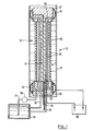
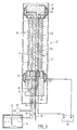
- Figure 1 is a cross sectional view of a probe for insertion into a tube having sealing means at each end, fluid circulation means and an electrode.
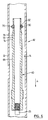
- Figure 2 is a cross sectional view of an alternative probe for performing the process.
- Figure 3 is cross sectional view of the upper portion of a probe having thermally expandable O-ring sealing means, wherein the probe is sealed in a tube.
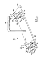
- Figure 4 is a perspective view of a clamp for use in compressing O-ring seals of a probe of Fig. 3.
- Figure 5 is a perspective view of a probe with the clamp of Figure 4 attached thereto.
- Figure 6 is a cross sectional view of the probe portion of Figure 3 wherein the probe is being removed from the tube.
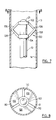
- Figure 7 is a cross sectional view of a probe according to a further embodiment of this invention.
- Figure 8 is a top plan view in the direction of line 8 - 8 of Figure 7.
- Figure 9 is a cross sectional view of a further embodiment of a probe according to this invention.
- Figure 10 is a cross sectional optical photomicrograph (100X) showing an electrodeposited nickel layer produced according to the invention.
- Figure 11 is a transmission electron micrograph (15000X) showing the ultra-fine grain structure and high degree of twinning for a nickel layer produced according to the invention.
- the invention will be described in relation to the in situ repair of metal tubes such as heat exchanger tubes made of any of the commercial iron, copper and nickel based alloys.
- the electrodeposited metal layer deposited according to the invention may comprise any commercial iron, nickel, chromium or copper bearing alloy.
- the internal diameter of the tube being repaired is at least 5 mm, but typically is in the range 10 mm to 50 mm; and the length of tube section being repaired may be as short as 5 mm, but typically is in the range 100 mm to 900 mm.
- the following description illustrates the method of the invention as it relates to the deposition of nickel on the internal wall of a tube. The artisan will appreciate that the invention has a more general application than that specifically described herein.
- a probe 10 is inserted into a metal tube 12, such as a nickel/copper alloy heat exchanger tube, and manipulated to a section 13 of the tube 12 requiring repair.
- the tube section 13 has an inner wall 14.
- the probe 10 has seals 15, which are preferably inflatable, at each end to isolate the probe 10 within the tube section 13 and to contain electrolyte and other process fluids within the section 13.
- the seals 15 are inflated through a capillary air line 17 connected to a pressurized air supply preferably in the range 10-40 psig.
- the seals 15 are provided about end base 20 and head 21 pieces which preferably are cylindrical in shape.
- An outer tubular porous plastic housing 23 which may be a plastic weave such as polypropylene, extends between the base 20 and head 21, and contains an electrode 25, which is the anode under electrodeposition conditions at the tube wall 14 and which preferably is a flexible porous tubular member made of woven Pt wire extending between the base 20 and head 21 of the probe 10.
- the flexible housing 23 provides an interface between the anode and cathode, i.e, the electrode 25 and tube 13; thus, preventing shorting during electrodeposition.
- the housing also hinders interference with the metal deposition at the tube wall 14 which may be caused by gases or sludge particles generated during electrodepositing. Fluids are circulated through the tube section 13 via a feed inlet means 28 and an outlet means 29 formed in the base 20 and head 21 respectively.
- Conduits 31 and 32 connect the inlet and outlet means 28 and 29 with a reservoir 34 and associated pump means 35.
- a thermocouple 36 is provided through the base 20 to monitor the temperature during electrodepositing.
- the anode 25 and tube section 13 (cathode) are connected to a direct current power supply 38 by means of suitable conductor leads.
- the air line 17, conduits 32, tubular anode 25, and tubular plastic housing 23 are all flexible to allow the probe 10 to be snaked through a tube 12 having curves or bends in it.
- pressurized air is provided through the line 17 thereby inflating the seals 15.
- the seals 15 are toroidal rubber members which may be ribbed to provide a stronger grip against the inner tube wall 14.
- other sealing means such as thermally expandable O-rings, may be used to affect the same purpose as the inflatable seals 15 of this embodiment.
- different types of seals may be used at each end of the probe 10. In some applications, it may be useful to have an inflatable seal 15 at the base 20 with the seal at the other end of the probe 10 being effected by a separate removable plug (not shown).
- Fluids may be delivered to and circulated through the seated probe 10 via the inlet and outlet means 28 and 29 with their associated conduits 31 and 32.
- the conduits 31 and 32 may be quite long (e.g., up to 500 ft.) depending on the application. While only one fluid reservoir 34 is shown in Fig. 1, clearly, a plurality of fluid reservoirs can be used with appropriate valving to supply and circulate the process fluids to and through the probe 10.
- a preferred fluid delivery system for the probe 10 will include pumps, valves and programmable controlling and monitoring devices to provide fluid flows through the probe 10 under precise flow rate, pressure and temperatures conditions.
- the power supply 38 is a commercial pulse plating direct current unit having a 400A/20V peak output.
- a busbar (not shown) may be used to connect a plurality of probes 10 which are inserted into a plurality of tubes 12.
- Heat exchanger tubes utilized in nuclear generating plants typically have diameters from 10 mm to 25 mm.
- the electrode 25 of the probe 10 has a diameter from 1 mm to 12.5 mm, more preferably from 2 mm to 10 mm, and most preferably, from 3 mm to 10 mm.
- a suitable electrode 25 for use in the invention has a composite structure with an inner layer of structural metal and an outer layer of platinum.
- the inner structural metal layer must have high strength and ductility despite the dimensions of the electrode 25.
- the metal must not be deleterious to the electrodepositing process and must be corrosion resistant so as to maintain its structural integrity despite the electrodepositing solutions which pass through the probe 10.
- the inner metal layer is titanium or niobium.
- the titanium and platinum forming the electrode 25 are preferably cold worked so as to maintain their strength. Accordingly, the titanium and platinum are each fully hard. The platinum may be clad on the titanium by first preparing the inner titanium layer, and then extruding the platinum onto it.
- the inner metal layer preferably is from 100 microns to 2 mm thick, more preferably from 250 microns to 1 mm thick, and most preferably, from 250 microns to 500 microns thick.
- the outer platinum layer is preferably from 50 microns to 250 microns thick, more preferably from 75 microns to 250 microns thick, and most preferably, from 100 microns to 200 microns thick.
- FIG. 2 An alternative probe 50 is shown in Figure 2.
- the structure of the probe 50 is essentially the same as that of the probe 10 ( Figure 1) except that the tubular porous housing 53 and anode 55 are sized and positioned to accommodate the inclusion of pellets of pure metal, e.g. (Ni) 57, within the tubular anode 55.
- the metal pellets 57 oxidize and the metal ions are reduced on the cathode surface, thus driving the reaction toward metal deposition a the cathode (tube wall 14).
- filters 59 are provided at inlets 61 and outlets 62 within the anode 55.
- thermally expandable O-ring seals may be used with a probe 40 of the invention as shown in Figures 3 - 6.
- Figure 3 shows a tube section 13 which is sealed by a thermally expandable O-ring 70.
- the O-ring 70 sits in a recess 72 of a probe end 65.
- the probe end 65 is preferably made of a dimensionally stable, chemically inert, machinable plastic such as that sold by DuPont under the trademark TORLON.
- the recess 72 has a lower abutting annular face 74 and an upper abutting annular face 76.
- the O-ring 70 extends from the recess 72 outwardly to the inner wall 14 of the tube section 13, thereby sealing the end of the probe 40.
- the O-ring 70 is circular in cross section in its relaxed state.
- the faces 74 and 76 provide resistance to the travel of the O-ring 70 along the exterior surface of the probe end 65 as the probe 40 is inserted into the tube 12 as well as during the electrodepositing process.
- a probe 40 having thermally expandable O-rings 70 has ends 65 and 66 (not shown) at either end of an electrode 25.
- the probe end 66 is essentially the same in structure as the end 65 except that where the end 65 has a trough 90 and abutting annular surface 92 defined beyond the recess 72 toward the end of the probe 40, the end 66 has a trough 90 and abutting surface defined beyond the recess 72 toward the electrode 25 of the probe 40. The reason for this structuring will be apparent from the following description.
- the O-ring 70 is positioned in the recess 72 of the probe end 65.
- the O-ring 70 must be deformed so that the surface of the O-ring 70 opposite the recess 72 will not contact the tube wall 14 as the probe 40 is inserted therein.
- a clamp 80 which is shown in Figure 4, is utilized to compress the O-ring 70 to reduce the outside diameter sufficiently to enable insertion of the probe 40 into the tube section 13.
- the clamp 80 comprises a base 120, a first clamping means 122, a second clamping means 124 and a handle 126.
- the first and second clamping means 122 and 124 are positioned on the upper surface 128 of the base 120 and are located at opposed ends of the base 120.
- the clamp 120 is adapted for a probe 40 which has an O-ring 70 at either end. Accordingly, the first and second clamping means 122 and 124 are positioned a sufficient distance apart so that each end of the probe 40 which includes an O-ring 70 may be received therein.
- Each clamping means 122 and 124 comprises a lower portion 130 and an upper portion 132 which are pivotally connected by means of a hinge 134 between an open position (see Figure 4) and a closed position (see Figure 5).
- the lower portion 130 has an upper surface 136 in which a recess 138 is provided.
- the upper portion 132 has an inner surface 140 in which a recess 142 is provided.
- the recesses 138 and 142 define a cavity in which the probe end 65 having the O-ring 70 may be received.
- the circumference of the cavity is sufficiently small so that the O-ring 70 will be deformed (i.e., forced to deform laterally in the axial direction of the probe 40) when the clamping means 122 is closed.
- the circumference of the cavity is selected so that the probe 40 with the deformed O-rings 70 will be able to be inserted into the tube 12 to be treated.
- the inner surface 136 has an upwardly extending flange member 144.
- the upper portion 132 is provided with a mating recess 146 such that when the clamping means is closed, the flange 144 is received in the recess 146.
- the upper portion 132 and the flange 144 are provided with laterally extending openings 148 which align when the clamp 80 is closed.
- a probe 40 is placed axially along the base 120 such that the O-ring 70 at each end of the probe 40 is received in the recesses 138.
- the upper portion 132 of each clamping means 122 and 124 is then closed to the position shown in Figure 5.
- the clamping means 122 and 124 may be closed by applying pressure to move the upper portions 132 pivotably downwardly so that the upper surfaces 136 contact the inner surfaces 140.
- a rod 150 is then inserted through the aligned openings 148 locking the clamping means 122 and 124 in the closed position.
- the O-rings 70 are then sufficiently cooled so that they will temporarily remain deformed when the probe 40 is removed from the clamp 80.
- the degree of cooling which is required will depend upon various factors including the composition of the O-ring 70 as well as the amount of time which will be required to position the probe 40 in the tube section 13.
- the O-ring 70 is preferably frozen by reducing its temperature to less than -90°C, more preferably to less than -120°C, and most preferably, to -170°C to -196°C.
- the O-ring 70 may be frozen by immersing it into liquid nitrogen (-196°C). The immersion may be achieved by lifting the clamp 80 by the handle 126.
- the cooling is very rapid and the clamp 80 may only be immersed in the liquid nitrogen for about 5 minutes to attain the desired temperature.
- the clamp 80 is then removed from the liquid nitrogen, the rods 150 are removed, the clamping means 122 and 124 are opened, and the probe 40 is removed from the clamp 80.
- the probe 40 is then ready for insertion into a tube 12. Due to the temperature extremes to which the clamp 80 is subjected, it is manufactured from a material, such as carbon steel which may withstand the rapid temperature changes without structural failure.
- the O-ring 70 will remain in the deformed state for about 5 minutes while the probe 40 is inserted into the tube section 13. Once the probe 40 is properly positioned, the O-ring 70 will warm and expand to its original shape contacting the tube wall 14 and providing a positive seal for the probe 40. Once in position, the seal may withstand pressures of up to 100 psi without any substantial leaks developing. In comparison, inflatable seals 15 which were described with respect to Figure 1 may typically withstand pressures of about 20 psi.
- the probe 40 may be removed simply by pulling the probe 40 out of the tube 12.
- the O-rings 70 at either end 65 and 66 are caused to roll over the abutting faces 76 and into the troughs 90 where they are retained in position by the abutting faces 92.
- the troughs 90 are sufficiently recessed so that the outer wall of the O-rings 70, when in the relaxed state, do not contact the tube wall 14 as the probe 40 is moved therein.
- the O-ring 70 may be made of any elastomeric material which is capable of being deformed and frozen in the deformed position.
- the elastomeric material may be a natural or synthetic rubber.
- the elastomeric material must be resistant to chemical degradation by the chemicals utilized in the process.
- the O-ring 70 is prepared from a polyfluorocarbon such as that sold under the trademark VITON.
- one end of the probe 10 may have a seal and the other end may merely be covered by the electrolyte or other process fluid.
- the tube 12 may be vertically disposed, then the lower end of the probe 10 (e.g., the base 20) may be sealed with an inflatable seal 15 or an O-ring 70.
- the head 21 may not have a seal.
- the tube 12 may be pressurized with air from the end of the tube opposite the end from which the probe 10 is inserted to contain process fluids about the electrode 25 and to ensure that electrode 25 is, at all times, covered with the electrolyte or other process fluids.
- a spacer 100 is provided adjacent the head 21 to position the probe 10 in the centre of the tube section 13 and to maintain the probe 10 at that position during the electrodepositing process.
- the spacer 100 has an upper circular portion 102 and a lower circular portion 104.
- the circular portions 102 and 104 are fixed by any suitable means known in the art to the probe 10.
- An upper arm 106 extends downwardly from the upper circular portion 102 to the inside wall of tube section 13.
- a lower arm 108 extends upwardly from the lower circular portion 104 to the inner wall 14 of tube section 13.
- the arms 106 and 108 meet at the tube wall. As seen in Figure 8, the arms 106 and 108 extend substantially over the cross section of the tube 12.
- Openings 110 are positioned between the arms 106 and 108 to permit the electrolyte, or other fluids to flow therethrough.
- the air pressure in the tube 12 will vary depending upon the rate of fluid flow in the electrochemical cell defined by the probe 10 and the tube wall 14. The air pressure is greater than the fluid pressure in the electrochemical cell.
- conduits 31 and 32 may be quite long, for example up to about 500 ft. Due to the narrow size of these conduits, substantial frictional losses are encountered as the electrolyte flows through the conduit 31 to the probe 10 and is returned to the reservoir via the conduit 32. In order to reduce the entanglement of conduits 31 and 32, the return conduit 32 is typically positioned coaxially within the conduit 31.
- the pressure in the electrochemical cell defined by the probe 10 and the tube section 13 may be substantially reduced by positioning the feed conduit 31 within the return conduit 32 and providing a flow reverser in the base 20 (see Figure 9).
- fresh electrolyte is pumped through the conduit 31 into the coaxial conduit 33 which extends from the reservoir 34 to the base 20 of the probe 10. This comprises the majority of the length of the electrolyte conduits.
- the inner coaxial conduit 31 divides out of the outer coaxial conduit 32.
- the conduit 31 extends to the feed inlet means 28, and the feed outlet means 29 drains into the conduit 32.
- the cross-sectional area of the annular portion of the conduit 32 through which the returned electrolyte flows is larger than the cross-sectional layer of the conduit 31 (through which the fresh electrolyte flows). Accordingly, in the coaxial conduit 33 the fresh electrolyte passing through the inner conduit 31 sustains greater frictional loss than the returned electrolyte flowing through the conduit 32. As a result, the pressure in the fresh electrolyte stream where it enters the electrochemical cell is substantially reduced. The reduced pressure in the electrochemical cell reduces the risk of a leak in the seal 15 at head 21 of the probe. Further, it allows a greater rate of flow of electrolyte through the electrochemical cell, thus permitting increased plating rates.
- a preferred process will now be described in relation to the electrodeposition of nickel on the wall 14 of a tube 12.
- various metals or alloys can be electrodeposited on the tube wall 14 by using the appropriate metals or metal salts moulder the necessary electrochemical conditions.
- the chemistry of electrodepositing is well known.
- heat exchanger tubes such as used in power generating facilities are made of a nickel/copper alloy, so the electrodeposition of a nickel layer to repair a degraded tube section 13 of such a heat exchanger tube would in most instances be preferred.
- the preferred process of the invention comprises initial surface preparation of the inner wall 14 of the tube section 13, the electrodeposition of a transition film of metal or a strike, and electrodepositing of the structural metal layer repairing the tube section 13.
- the inner surface 14 of the degraded tube section 13 is mechanically cleaned by, for example, brushing or water lancing to remove any loose or semi-adherent deposits.
- the probe 10 is then inserted into the tube 12 and manipulated to span the degraded section 13.
- the probe 10 is secured in place in the tube 12 by inflating the seals 15 as described.
- the secured probe 10 and tube section 13 define an electrochemical cell.
- the tube section 13 is degreased by circulating an aqueous solution of 5% NaOH through the probe 10 at a flow rate of 100-400 ml/min., preferably 300-400 ml/min.
- the flow of fluid through the probe 10 is via the conduits 31 and 32 as described.
- a current density of 10-100 mA/cm 2 is applied between the anode 25 and cathode (tube section 13) for 5-10 min. to vigorously generate hydrogen gas at the inner tube wall surface 14, thereby removing all remaining soils and particulates from the tube surface 14.
- This degreasing step is followed by a rinsing flow of deionized water through the tube section 13 for about 5 min.
- a dilute aqueous solution of strong mineral acid e.g. 5%-20% HCl
- a transition film of metal or a strike may then be electrodeposited.
- a strike layer is typically required where the metal on which the electrodeposition is occurring is a passive metal or alloy, such as stainless steel or chromium containing nickel alloys. However, if the metal comprises primarily an active or noble metal or alloy such as iron or copper, then a strike layer may not be required.
- a solution of NiCl 2 (200-400 g/l) and boric acid (30-45 g/l) as a buffer in water at 60°C is circulated through the tube section 13 at a rate of 100-400 ml/min., preferably, 300-400 ml/min.
- a current density of 50 mA/cm 2 to 300 mA/cm 2 is applied across the electrodes for 2-15 min. to allow the deposition of a thin strike of nickel on the inner tube wall 14.
- a pulsed direct current is preferred for this step and is applied with an average current density of 50-300 mA/cm 2 , preferably 50-150 mA/cm 2 , at a frequency of 10-1000 Hz, preferably, 100-1000 Hz, with an on-time or duty cycle of 10-60%, preferably 10-40%.
- Chloride in the electrolyte acts to etch the wall surface 14, thereby assisting the formation of a strong bond between the wall 14 and the strike layer and promoting a continuous metallic interface between the wall 14 and the strike layer.
- the strike layer should be sufficiently thick to ensure that the portion of the tube wall 14 to be treated does not contain any bare spots.
- the strike layer has a thickness from 2 to 50 ⁇ m, more preferably from 5 to 20 ⁇ m and, most preferably from 10 to 15 ⁇ m.
- the tube section 13 preferably is rinsed with deionized water, at 60°C with a flow rate of 100 - 1000 ml/min. for 5 - 20 min. to remove chloride carry over.
- a structural layer of fine grained nickel is then electrodeposited onto the strike by circulating through the tube section 13 an electrolyte comprising an aqueous solution of NiSO 4 (300-450 g/l) and boric acid (30-45 g/l), preferably with low concentrations of additives such as sodium lauryl sulfate (surfactant), coumarin (leveler), and saccharin (brightener) each having a concentration not exceeding 1 g/l, preferably 60 mg/l, and applying a pulsed current as described below.
- Nickel cations are replenished in the electrolyte by the addition of NiCO 3 .
- the electrolyte preferably contains a pinning agent such as phosphoric acid as described below.
- sodium lauryl sulfate acts to reduce the surface tension of the electrolyte, thereby reducing or eliminating pitting in the surface of the deposited layer.
- Coumarin acts as a leveler to assist the filling of micro-cracks in the electrodepositing layer.
- Saccharin acts to smooth out the surface of the metal layer during electrodepositing and reduces stresses in the deposit.
- the electrodepositing solution is circulated at a temperature of 25-90°C to enhance reaction kinetics, and a pulsed average direct current density of 50-300 mA/cm 2 is applied across the electrodes 25 and 13.
- the average direct current density is preferably 50-150 mA/cm 2 .
- the pulsing of the current proceeds at a frequency of 10-1000 Hz, preferably 100-1000 Hz, with the on-time or duty cycle being 10-60%, preferably 10-40%.
- the periodic reversal of polarity serves to reverse the electrodepositing process momentarily.
- Electrodepositing proceeds for sufficient time to allow the formation of a structural layer of nickel having the desired thickness, typically 0.1-2 mm.
- the tube section 13 preferably is rinsed with deionized water, preferably at about 60°C, at a flow rate of 100-400 ml/min. for 5-20 min. to remove all residual process chemicals.
- the seals 15 are deflated and the probe 10 is removed.
- a structural layer of nickel may be electrodeposited onto the inner wall 14 of the tube section 13 in about 1 - 10 hrs.
- the process efficiency using the described platinum electrode is typically 70 - 100%, and may be in the range 90 - 100%. The efficiency generally varies within this range depending on the metal salts used and the average currrent density applied (i.e. a higher current density reduces efficiency). Process efficiency can be increased to essentially 100% by using a probe 50 as shown in Fig. 2 and described above.
- the electrodeposited layer produced according to the invention possesses an ultrafine grain microstructure wherein the grain sizes are in the range 20-5000 nm, preferably 20 - 1000 nm, more preferably 100 - 250 nm and most preferably the layer has an average grain size of 100 - 200 nm.
- the size of grains in process equipment varies from 20 to about 40 microns. Accordingly, the method of the present invention permits the deposition of crystals which are at least about one order of magnitude smaller than the metal substrate on which they are plated and may in fact be two or three orders of magnitude smaller. Accordingly, the structural layer so deposited forms a generally uniform coating on the metal surface treated to repair the corrosion or other degradation.
- the physical properties of a metal and its susceptibility to environmental degradation are related to its grain size, microstructure and chemistry.
- small grain size of a metal correlates with greater metal strength and higher ductility (for a review, see Fougere et al., Scripta Metall. et Mater., 26 , 1879 (1992)).
- the invention enables the production of an electrodeposited layer which has a fine grained structure with uniform chemical composition.
- the electrodeposited sleeve of the invention possesses enhanced strength while maintaining excellent ductility.
- the electrodeposited metal according to the invention has good resistance to corrosion.
- the structural layer which is electrodeposited may have a thickness from 0.1 - 2 mm.
- the thickness of the structure will depend upon the desired mechanical properties and corrosion resistance of the sleeve material relative to the initial design standards. For example, if a heat exchanger tube is being repaired, then the structural layer should be sufficiently thin so as not to interfere with the fluid flow through the tube or the heat transfer across it. Generally, the smaller the average grain size of the crystals, the stronger the structural layer. Accordingly, the smaller the grain size, the smaller the required thickness of the structural layer.
- the process can provide a high degree of crystal lattice twinning between grains.
- the invention allows the production of an electrodeposited layer which has greater than 10% twin boundaries, more preferably greater than 30% twin boundaries, and most preferably 50%-70% twin boundaries.
- a high degree of twin or "special" grain boundaries (such as twin boundaries) on the order of ⁇ 30%, correlates with greater resistance to grain boundary cracking mechanisms such as intergranular stress corrosion cracking as compared to metals not having such special grain boundaries (see Palumbo et al., Scripta Metall. et Mater., 25 , 1775 (1991)).
- Figure 10 shows a cross sectional optical photomicrograph (100X) showing an electrodeposited nickel layer produced in a tube according to the process of the invention.
- the uniform fine grained structure of the nickel layer is evident in this Figure.
- the high degree of twinning which is indicative of a high fraction of "special" grain boundaries in the structural nickel layer formed by the process of the invention is apparent from the 15,000X magnification of the micrograph of Figure 11.
- the fine grained, highly twinned microcrystalline structure of a nickel layer formed by the present process provides minimum mechanical properties as follows: Vickers hardness ⁇ 200; yield strength ⁇ 80,000 psi; tensile strength ⁇ 100,000 psi; and elongation to failure in bending ⁇ 10%; preferably Vickers hardness ⁇ 250; yield strengh ⁇ 100,000 psi; tensile strength ⁇ 150,000 psi; and elongation to failure in bending ⁇ 10%.
- Heat exchanger tubes such as nuclear steam generator tubes, typically operate at temperatures of about 300°C. At such temperatures, the grains in the electrodeposited metal tend to grow. The increase in the grain size results in decreased strength of the structural layer over time. To maintain the mechanical properties of the electrodeposited layer, it is preferred to inhibit the growth of the grains in the electrodeposited layer.
- the as plated grain size is stabilized by adding a grain boundary pinning agent.
- the pinning (stabilization) agent is phosphorus or molybdenum. Phosphorus may be introduced into the electrodeposited layer by adding a chemical that releases phosphorus such as phosphoric acid or phosphorous acid or both to the electrolyte.
- the electrolyte contains at least 0.1 g/l of the pinning agent, more preferably from 0.1 to 5 g/l and, most preferably 0.15 g/l of the stabilizing agent.
- an electrodeposited metal comprising from 400 to 4,000 ppm by weight phosphorus achieved the desired grain size stabilization.
- Corrosion resistance agents and strengthening agents may be added to the electrolyte to increase the strength or corrosion resistance or both of the electrodeposited metal.
- corrosion resistance agents are manganese sulfate, sodium molybdate and chromium salts such as chromium chloride.
- strengthening agents include manganese sulfate, sodium tungstate and cobalt sulfate. Up to about 50 g/l of each of these agents may be added to the electrolyte. Such additions result in electrodeposited metals containing less than 5 wt.% of each constituent metal of these agents.
- an electrodeposited material having two or more layers wherein abutting layers each have a different composition.
- a thick layer of nickel may be first electrodeposited on the area to be treated. Subsequently, a thin layer of the material from which the steam generator tube is manufactured may be electrodeposited. Electro-forming most of the thickness of the sleeve (e.g., about 90%) from nickel is advantageous due to the high plating rates that are possible. Further, the electrodeposition of nickel requires a relatively minimal amount of monitoring. Electrodepositing an outer layer which has a composition akin to that of the steam generator tube helps to ensure electrochemical compatibility in the operating environment.
Landscapes
- Chemical & Material Sciences (AREA)
- Engineering & Computer Science (AREA)
- Chemical Kinetics & Catalysis (AREA)
- Electrochemistry (AREA)
- Materials Engineering (AREA)
- Metallurgy (AREA)
- Organic Chemistry (AREA)
- Crystallography & Structural Chemistry (AREA)
- Physics & Mathematics (AREA)
- Thermal Sciences (AREA)
- Mechanical Engineering (AREA)
- General Engineering & Computer Science (AREA)
- Electroplating Methods And Accessories (AREA)
- Solid-Phase Diffusion Into Metallic Material Surfaces (AREA)
- Prevention Of Electric Corrosion (AREA)
Claims (46)
- Procédé pour la déposition électrolytique in situ d'une couche structurelle de renfort en métal qui adhère sur une paroi intérieure d'un tronçon dégradé (13) d'un tube en métal (12) fabriqué en fer, en cuivre, en nickel ou un alliage de l'un quelconque parmi le fer, le cuivre et le nickel, le procédé utilisant une sonde possédant une électrode souple (25) qui s'étend sensiblement le long de sa longueur, des moyens d'étanchement (15, 70) à l'une ou aux deux extrémités (20, 21 ; 65, 66) pour contenir des fluides à l'intérieur du tronçon de tube (13), et des moyens de circulation (31, 32, 35) pour amener des fluides à s'écouler vers l'intérieur et vers l'extérieur du tronçon de tube (13), le procédé comprenant les étapes suivantes:nettoyer par voie mécanique la surface de paroi interne dans ledit tronçon de tube (13) ;introduire une sonde (10) dans le tube en métal en faisant ainsi fléchir l'électrode (25) quand des courbes ou des coudes sont présents dans le tube (12) et déplacer cette sonde de telle sorte qu'elle s'étende le long du tronçon de tube dégradé ;dilater les moyens d'étanchement (15, 70) afin d'engager la paroi intérieure (14) du tube, en fixant ainsi l'électrode (25) dans le tronçon de tube (13) et en définissant une cellule afin de contenir l'écoulement de fluide à l'intérieur du tronçon de tube (13) ;déposer par voie électrolytique une couche structurelle de métal sur la paroi interne du tronçon de tube dégradé (13) en faisant s'écouler un électrolyte qui contient une quantité majeure de nickel sous forme ionique à travers le tronçon et en appliquant un courant continu par impulsions entre l'électrode (25) et le tube métallique (12) à une fréquence d'impulsions de 10 à 1.000 Hz avec un cycle utile dans la plage de 10 à 60% pendant une durée suffisante afin de déposer par voie électrolytique une couche métallique de 0,1 à 2 mm d'épaisseur, de sorte que le tronçon de tube (13) soit restauré dans ses propriétés mécaniques d'origine.
- Procédé selon la revendication 1,dans lequel le tube en métal présente un diamètre interne d'au moins 5 mm, et comprenant en outre l'étape, après avoir introduit la sonde (10), consistant à appliquer un courant électrique par impulsions entre l'électrode (25) et le tube en métal (12) tout en faisant s'écouler un électrolyte qui contient un sel de nickel métallique à travers le tronçon de tube (13) pour déposer par voie électrolytique une couche amorce de métal sur la paroi interne (14) du tronçon de tube (13), la déposition électrolytique étant effectuée pendant une durée suffisante pour déposer une couche amorce de 2 à 50 µm d'épaisseur sur la paroi du tube.
- Procédé selon la revendication 2,dans lequel l'électrode (25) est une anode et le tube de métal (12) est une cathode pendant la déposition électrolytique de métal sur la paroi interne du tube (14) ; et comprenant en outre l'étape consistant à activer la surface du métal de la paroi interne du tronçon de tube (13) juste avant la déposition électrolytique de la couche amorce, ladite activation étant accomplie en faisant s'écouler un fluide d'activation de surface à travers le tronçon de tube (13).
- Procédé selon la revendication 3,dans lequel le fluide d'activation est un acide minéral fort en solution aqueuse.
- Procédé selon la revendication 4,dans lequel le fluide d'activation est une solution aqueuse de 5 à 20% d'acide chlorhydrique que l'on fait circuler à travers le tronçon de tube à un débit de 100 à 400 ml/min pendant 5 à 10 minutes.
- Procédé selon la revendication 1,dans lequel le nettoyage mécanique est accompli par brossage.
- Procédé selon la revendication 1,dans lequel le nettoyage mécanique est accompli par projection d'eau.
- Procédé selon l'une quelconque des revendications 1 à 7, comprenant en outre l'étape consistant à dégraisser la surface interne (14) du tronçon de tube après introduction de la sonde (10).
- Procédé selon la revendication 8,dans lequel le dégraissage est accompli en faisant s'écouler une solution aqueuse de 5% d'hydroxyde à travers le tronçon de tube tout en appliquant une densité de courant de 10 à 100 mA/cm2 entre l'électrode (anode) et le tube de métal (cathode) pendant 5 à 10 minutes.
- Procédé selon la revendication 9,dans lequel le dégraissage utilise une solution aqueuse de 5% de NaOH sous le débit de 100 à 400 ml/min.
- Procédé selon la revendication 9,dans lequel comprenant en outre l'étape consistant à rincer le tronçon de tube (13) avec de l'eau désionisée après le dégraissage.
- Procédé selon la revendication 2,comprenant en outre l'étape consistant à rincer le tronçon de tube avec de l'eau désionisée après déposition électrolytique de la couche amorce.
- Procédé selon la revendication 1,dans lequel la déposition électrolytique de la couche structurelle en métal inclut l'inversion périodique de la polarité du courant continu appliqué par impulsions, lesdites inversions de polarité ayant lieu avec une densité de courant en moyenne plus faible que celle qui est utilisée pour la déposition électrolytique, et lesdites inversions ne dépassent pas environ 10% du cycle de service total.
- Procédé selon la revendication 3,dans lequel la couche structurelle de métal déposée par voie électrolytique est du nickel, la couche amorce étant déposée par voie électrolytique en utilisant un électrolyte qui contient NiC12, la couche structurelle étant déposée par voie électrolytique en utilisant un électrolyte qui contient NiSO4, et la déposition électrolytique est suivie d'un rinçage avec de l'eau désionisée.
- Procédé selon la revendication 14,dans lequel l'électrolyte pour la déposition électrolytique de l'amorce est une solution aqueuse de 200 à 400 g/l de NiC12, et l'électrolyte pour la déposition électrolytique de la couche structurelle est une solution aqueuse de 300 à 450 g/l de NiSO4.
- Procédé selon la revendication 14,dans lesquels on ajoute 30 à 45 g/l d'acide borique en tant que tampon dans les électrolytes qui sont utilisés pour la déposition électrolytique de l'amorce et la déposition électrolytique de la couche structurelle.
- Procédé selon la revendication 14,dans lequel on utilise du NiCO3 pour compléter les cations de nickel enlevés de l'électrolyte pendant la déposition électrolytique de la couche structurelle.
- Procédé selon la revendication 16,dans lequel l'électrolyte pour la déposition électrolytique de la couche structurelle contient également du sodium-lauryl-sulfate, de la coumarine ou de la saccharine, ou une combinaison quelconque de ceux-ci, ayant chacun une concentration qui ne dépasse pas 1 g/l.
- Procédé selon la revendication 15,dans lequel l'électrolyte pour la déposition électrolytique de l'amorce est à environ 60°C, et l'on applique entre l'anode et la cathode un courant continu avec une densité de 50 à 300 mA/cm2 pendant 2 à 15 minutes.
- Procédé selon la revendication 15,dans lequel l'électrolyte pour la déposition électrolytique de l'amorce est à environ 60°C, et l'on applique un courant continu par impulsions entre l'anode et la cathode avec une densité de courant moyenne de 50 à 150 mA/cm2 à une fréquence de 100 à 1.000 Hz et un cycle de service de 10 à 40% pendant 2 à 15 minutes.
- Procédé selon la revendication 1,dans lequel l'électrolyte pour la déposition électrolytique la couche structurelle est à 25 à 90°C, et l'on applique un courant continu par impulsions entre l'anode et la cathode avec une densité de courant moyenne de 50 à 300 mA/cm2 pendant 1 à 10 heures.
- Procédé selon la revendication 21,dans lequel la déposition électrolytique de la couche structurelle inclut des inversions de polarité périodiques du courant continu par impulsions, lesdites inversions de polarité étant à une densité de courant en moyenne plus faible que celle qui est utilisée pour la déposition électrolytique, et lesdites inversions ne dépassant pas environ 10% du cycle de service total.
- Procédé selon la revendication 1,dans lequel l'anode comprend du nickel métallique qui est ionisé et consommé pendant la déposition électrolytique.
- Procédé selon la revendication 1,dans lequel l'électrolyte pour la déposition électrolytique de la couche structurelle contient également un agent de pinning pour inhiber la croissance de grains métalliques dans la couche déposée par voie électrolytique.
- Procédé selon la revendication 24,dans lequel l'agent de pinning est du phosphore ou du molybdène.
- Procédé selon la revendication 25,dans lequel de l'acide phosphorique de l'acide phosphoreux, ou les deux, peuvent être ajoutés à l'électrolyte comme agent de pinning.
- Procédé selon la revendication 26,dans lequel l'agent de pinning présente une concentration de 0,1 à 5 g/l dans l'électrolyte.
- Procédé selon la revendication 27,dans lequel l'agent de pinning présente une concentration d'environ 0,15 g/l dans l'électrolyte.
- Procédé selon la revendication 1,dans lequel l'électrolyte pour la déposition électrolytique de la couche structurelle contient également un agent de résistance anticorrosion ou un agent de renfort, ou les deux.
- Procédé selon la revendication 29,dans lequel l'agent de résistance anticorrosion comprend l'un quelconque parmi le sulfate de manganèse, le molybdate de sodium, et les sels de chrome.
- Procédé selon la revendication 29,dans lequel l'agent de renfort comprend l'un quelconque parmi le sulfate de manganèse, le tungstate de sodium, et le sulfate de cobalt.
- Procédé selon la revendication 29,dans lequel chacun des agents de résistance anticorrosion et de renfort peut être présent dans l'électrolyte sous une concentration jusqu'à 50 g/l.
- Sonde capable d'être introduite dans un tube de métal, le tube ayant une paroi intérieure, ladite sonde comprenant :caractérisée en ce queune électrode (25) qui s'étend le long de la longueur de la sonde entre une première et une seconde extrémité (20, 21 ; 65, 66) de celle-ci ;des moyens d'étanchement (15, 70) à chaque extrémité (20, 21 ; 65, 66) de la sonde afin d'attacher l'électrode (25) dans un tronçon (13) du tube, en définissant ainsi une cellule, et pour contenir l'écoulement de fluide à l'intérieur du tronçon de tube (13) ;des moyens de circulation de fluide (31, 32, 35) assurant une communication en écoulement du fluide à travers la première extrémité (20 ; 65) de la sonde entre la cellule et un réservoir externe de fluide (34);ladite électrode (25) est souple de manière à lui permettre de se fléchir transversalement par rapport à sa longueur, etles moyens d'étanchement (15, 70) à l'une ou aux deux extrémités de la sonde (20, 21 ; 65, 66) sont dilatables.
- Sonde selon la revendication 33,dans laquelle la sonde est disposée verticalement lorsqu'elle est placée dans le tube, et lesdits moyens d'étanchement comprennent des moyens de centrage pour positionner la seconde extrémité supérieure (21) ;lesdits moyens de centrage ayant au moins une ouverture pour permettre la communication en écoulement du fluide vers la cellule.
- Sonde selon la revendication 33,dans laquelle les moyens d'étanchement à la première extrémité (20) sont constitués par un joint torique dilatable par voie thermique.
- Sonde selon la revendication 33,dans laquelle l'électrode (25) comprend une couche intérieure de métal structurel et une couche extérieure de platine plaquée sur le métal structurel.
- Sonde selon la revendication 36,dans laquelle le métal structurel est du titane.
- Sonde selon la revendication 37,dans laquelle le titane et le platine sont travaillés à froid, la couche intérieure ayant une épaisseur de 100 µm à 2 mm, et la couche extérieure ayant une épaisseur de 50 à 250 µm.
- Sonde selon la revendication 33,dans laquelle chaque extrémité de la sonde comporte un premier et un second évidement (72, 92) pour recevoir un joint torique dilatable par voie thermique (70), ledit premier évidement (92) étant plus profond que ledit second évidement (72), de sorte que lorsque la sonde est dans le tube et que chaque joint torique (70) est dans le premier évidement (92), chaque joint torique n'est pas en contact avec la paroi du tube, et de telle sorte que lorsque la sonde est dans le tube et que chaque joint torique (70) est dans le second évidement (72) et que chaque joint torique est dans son état dilaté,chaque joint torique (70) est en contact avec la paroi du tube, en assurant ainsi une étanchéité.
- Sonde selon l'une ou l'autre des revendications 33 ou 39,dans laquelle les moyens de circulation de fluide comprennent un conduit d'alimentation en fluide frais (31) et un conduit de retour de fluide utilisé (32), le conduit d'alimentation de fluide frais (31) étant positionné à l'intérieur du conduit du retour de fluide utilisé (32).
- Sonde selon la revendication 40,dans laquelle la superficie d'écoulement transversale du conduit d'alimentation de fluide frais (31) est plus petite que la superficie d'écoulement transversale du conduit de retour de fluide utilisé (32).
- Sonde selon la revendication 40,comprenant en outre un boítier tubulaire poreux, souple et non-conducteur (23, 53) qui entoure l'électrode souple (25) le long de la longueur entière de l'électrode, ledit boítier (23, 53) étant espacé vers l'extérieur depuis l'électrode (25) et, lorsque l'électrode (25) est positionnée dans un tube, ledit boítier étant espacé vers l'intérieur depuis la paroi du tube.
- Sonde selon la revendication 42,comprenant en outre des pastilles (57) d'un métal à déposer par voie électrolytique, disposées sur la paroi interne du tube.
- Sonde selon la revendication 42,dans laquelle l'électrode souple (25) comprend une pluralité de tronçons souples dont chacun est flexible par rapport aux tronçons en butée.
- Sonde selon la revendication 44,dans laquelle l'électrode souple est réalisée avec un fil en platine.
- Sonde selon l'une quelconque des revendications 40 à 45, prise en dépendance de la revendication 33, dans laquelle lesdits moyens d'étanchement dilatables comprennent des joints (15) gonflables avec de l'air sous pression.
Applications Claiming Priority (3)
| Application Number | Priority Date | Filing Date | Title |
|---|---|---|---|
| US152714 | 1993-11-16 | ||
| US08/152,714 US5516415A (en) | 1993-11-16 | 1993-11-16 | Process and apparatus for in situ electroforming a structural layer of metal bonded to an internal wall of a metal tube |
| PCT/CA1994/000632 WO1995014122A1 (fr) | 1993-11-16 | 1994-11-15 | Procede et dispositif destines a realiser par electrodeposition in situ une couche structurale metallique soudee a la paroi interne d'un tube metallique |
Publications (2)
| Publication Number | Publication Date |
|---|---|
| EP0729523A1 EP0729523A1 (fr) | 1996-09-04 |
| EP0729523B1 true EP0729523B1 (fr) | 1999-02-24 |
Family
ID=22544089
Family Applications (2)
| Application Number | Title | Priority Date | Filing Date |
|---|---|---|---|
| EP95900582A Expired - Lifetime EP0729523B1 (fr) | 1993-11-16 | 1994-11-15 | Procede et dispositif destines a realiser par electrodeposition in situ une couche structurale metallique soudee a la paroi interne d'un tube metallique |
| EP95900581A Expired - Lifetime EP0729522B1 (fr) | 1993-11-16 | 1994-11-15 | Tube metallique avec section presentant une couche structurale interne obtenue par electrodeposition |
Family Applications After (1)
| Application Number | Title | Priority Date | Filing Date |
|---|---|---|---|
| EP95900581A Expired - Lifetime EP0729522B1 (fr) | 1993-11-16 | 1994-11-15 | Tube metallique avec section presentant une couche structurale interne obtenue par electrodeposition |
Country Status (8)
| Country | Link |
|---|---|
| US (3) | US5516415A (fr) |
| EP (2) | EP0729523B1 (fr) |
| KR (2) | KR100230196B1 (fr) |
| CN (2) | CN1044729C (fr) |
| AU (2) | AU8137194A (fr) |
| CA (2) | CA2175597C (fr) |
| DE (2) | DE69416689T2 (fr) |
| WO (2) | WO1995014121A1 (fr) |
Families Citing this family (70)
| Publication number | Priority date | Publication date | Assignee | Title |
|---|---|---|---|---|
| FR2731498B1 (fr) * | 1995-03-08 | 1997-06-06 | Framatome Sa | Procede de reparation par chemisage electrolytique d'un tube tel qu'un tube de generateur de vapeur |
| JP3081558B2 (ja) * | 1997-04-30 | 2000-08-28 | 株式会社ダイワエクセル | 内面めっき方法及び内面めっき用補助極 |
| US6080504A (en) * | 1998-11-02 | 2000-06-27 | Faraday Technology, Inc. | Electrodeposition of catalytic metals using pulsed electric fields |
| USRE40386E1 (en) * | 1998-11-06 | 2008-06-17 | Hitachi Ltd. | Chrome plated parts and chrome plating method |
| US6258239B1 (en) * | 1998-12-14 | 2001-07-10 | Ballard Power Systems Inc. | Process for the manufacture of an electrode for a solid polymer fuel cell |
| DE19925373B4 (de) * | 1999-06-02 | 2006-04-06 | Robert Bosch Gmbh | Verfahren und Vorrichtung zum Galvanisieren |
| DE19954652A1 (de) * | 1999-11-13 | 2001-05-17 | Rheinmetall W & M Gmbh | Verfahren zur Innenbeschichtung eines Waffenrohres |
| DE10001888A1 (de) * | 2000-01-19 | 2001-07-26 | Rheinmetall W & M Gmbh | Verfahren zur Innenbeschichtung eines Waffenrohres |
| US6378904B1 (en) * | 2001-01-08 | 2002-04-30 | James Patrick Niehoff | ATV trailer |
| DE10109138C2 (de) * | 2001-02-26 | 2003-12-11 | Hew Ag | Bauteile für den Kesselbereich von Kraftwerken oder Müllverbrennungsanlagen |
| KR100469084B1 (ko) * | 2002-03-25 | 2005-02-02 | 한국수력원자력 주식회사 | 설파메이트 욕을 이용한 Ni―Fe―P 합금도금 방법 |
| EP1507612B1 (fr) * | 2002-05-27 | 2013-12-11 | Concast Ag | Procede d'enduction galvanique d'une coquille pour la coulee continue |
| US7560015B2 (en) * | 2002-05-27 | 2009-07-14 | Concast Ag | Process for electrolytic coating of a strand casting mould |
| US20030234181A1 (en) * | 2002-06-25 | 2003-12-25 | Gino Palumbo | Process for in-situ electroforming a structural layer of metallic material to an outside wall of a metal tube |
| AU2003212164A1 (en) * | 2002-06-25 | 2004-01-06 | Integran Technologies Inc. | Process for in-situ electroforming a structural layer of metallic material to an outside wall of a metal tube |
| US6902827B2 (en) * | 2002-08-15 | 2005-06-07 | Sandia National Laboratories | Process for the electrodeposition of low stress nickel-manganese alloys |
| EP1464732A1 (fr) * | 2003-03-31 | 2004-10-06 | Tecnol S.p.A. | Dispositif et méthode pour l'application d'un revêtement sur un élément métallique |
| US7445697B2 (en) * | 2003-10-22 | 2008-11-04 | Nexx Systems, Inc. | Method and apparatus for fluid processing a workpiece |
| DE102004051374A1 (de) * | 2003-10-30 | 2005-06-02 | Sumitomo Electric Industries, Ltd. | Galvanogeformtes Ionenimplantations-Strukturmaterial und Verfahren zur Herstellung des Strukturmaterials |
| EP1745247B1 (fr) * | 2004-04-23 | 2015-11-11 | Philip Morris Products S.a.s. | Generateurs d'aerosol et procede de production d'aerosols |
| US20060118411A1 (en) * | 2004-12-07 | 2006-06-08 | H & T Marsberg Gmbh & Co. Kg | Process and apparatus for multiple surface treatments of battery cans |
| US7387578B2 (en) * | 2004-12-17 | 2008-06-17 | Integran Technologies Inc. | Strong, lightweight article containing a fine-grained metallic layer |
| US7320832B2 (en) * | 2004-12-17 | 2008-01-22 | Integran Technologies Inc. | Fine-grained metallic coatings having the coefficient of thermal expansion matched to the one of the substrate |
| CA2619509C (fr) | 2005-08-12 | 2015-01-06 | Modumetal, Llc. | Materiaux composites a composition modulee et leurs procedes de fabrication |
| US8101050B2 (en) * | 2006-06-20 | 2012-01-24 | Vetco Gray Inc. | System, method, and apparatus for continuous electroplating of elongated workpieces |
| US20100096850A1 (en) * | 2006-10-31 | 2010-04-22 | Massachusetts Institute Of Technology | Nanostructured alloy coated threaded metal surfaces and methods of producing same |
| US7875161B2 (en) * | 2006-12-28 | 2011-01-25 | Hamilton Sundstrand Corporation | Method for electrodepositing a coating on an interior surface |
| US8257572B2 (en) * | 2008-03-28 | 2012-09-04 | Tenaris Connections Limited | Method for electrochemical plating and marking of metals |
| JP5195072B2 (ja) * | 2008-06-25 | 2013-05-08 | スズキ株式会社 | シリンダブロックのめっき処理装置及び方法 |
| CN102438823B (zh) * | 2009-03-24 | 2017-12-12 | 通用电器技术有限公司 | 疲劳腐蚀开裂的金属管的涂覆 |
| US8247050B2 (en) * | 2009-06-02 | 2012-08-21 | Integran Technologies, Inc. | Metal-coated polymer article of high durability and vacuum and/or pressure integrity |
| BRPI1010877B1 (pt) | 2009-06-08 | 2020-09-15 | Modumetal, Inc | Revestimento de multicamadas resistente à corrosão e método de eletrodeposição |
| JP5338500B2 (ja) * | 2009-06-10 | 2013-11-13 | スズキ株式会社 | シリンダブロックめっき処理装置のシール治具及びシール方法 |
| JP4629154B1 (ja) * | 2010-03-23 | 2011-02-09 | Jx日鉱日石金属株式会社 | 電子材料用銅合金及びその製造方法 |
| US20130004793A1 (en) * | 2011-03-23 | 2013-01-03 | Hiroshi Kuwagaki | Copper alloy for electronic material and method of manufacture for same |
| KR101370310B1 (ko) * | 2011-10-13 | 2014-03-06 | 한닢테크(주) | 반도체 실리콘잉곳 제조용 반응로의 내부표면 도금방법 |
| DE102012109812A1 (de) * | 2012-10-15 | 2014-04-17 | Noatzke Verwaltungs GmbH | Eloxiervorrichtung und Eloxierverfahren |
| JP5986925B2 (ja) * | 2012-12-28 | 2016-09-06 | 三菱重工業株式会社 | 回転機械の製造方法、回転機械のめっき方法 |
| BR112015022020A8 (pt) | 2013-03-15 | 2019-12-10 | Modumetal Inc | objeto ou revestimento e seu processo de fabricação |
| WO2014146117A2 (fr) | 2013-03-15 | 2014-09-18 | Modumetal, Inc. | Procédé et appareil d'application en continu de revêtements métalliques nanostratifiés |
| CA2905548C (fr) | 2013-03-15 | 2022-04-26 | Modumetal, Inc. | Revetements nanostratifies |
| EA201500948A1 (ru) | 2013-03-15 | 2016-03-31 | Модьюметл, Инк. | Способ изготовления изделия и изделие, изготовленное вышеуказанным способом |
| JP6189656B2 (ja) | 2013-06-14 | 2017-08-30 | Kyb株式会社 | 給電部材及びそれを備えた高速めっき装置 |
| JP6193005B2 (ja) | 2013-06-14 | 2017-09-06 | Kyb株式会社 | 保持装置及びそれを備えた高速めっき装置 |
| CN105980608B (zh) * | 2013-12-13 | 2017-11-24 | 新日铁住金株式会社 | 钢管的电镀装置 |
| US9303328B2 (en) | 2014-01-09 | 2016-04-05 | Teledyne Instruments, Inc. | System and method for electroplating of hole surfaces |
| GB2528873A (en) * | 2014-07-31 | 2016-02-10 | Mohammad Sakhawat Hussain | Direct high speed nickel plating on difficult to plate metals |
| EP3194642A4 (fr) | 2014-09-18 | 2018-07-04 | Modumetal, Inc. | Procédé et appareil d'application en continu de revêtements métalliques nanostratifiés |
| BR112017005534A2 (pt) | 2014-09-18 | 2017-12-05 | Modumetal Inc | métodos de preparação de artigos por processos de eletrodeposição e fabricação aditiva |
| US9903521B2 (en) * | 2014-10-01 | 2018-02-27 | Richard L. Glenn | Upstream pipe plug |
| US20170016131A1 (en) * | 2015-07-15 | 2017-01-19 | Far East University | Growth method of dendritic crystal structure that provides directional heat transfer |
| US10197165B1 (en) | 2016-02-03 | 2019-02-05 | The United States Of America As Represented By The Administrator Of Nasa | Cold installation of elastomeric valve seat |
| US11365488B2 (en) | 2016-09-08 | 2022-06-21 | Modumetal, Inc. | Processes for providing laminated coatings on workpieces, and articles made therefrom |
| TW201821649A (zh) | 2016-09-09 | 2018-06-16 | 美商馬杜合金股份有限公司 | 層合物與奈米層合物材料於工具及模製方法之應用 |
| WO2018053158A1 (fr) | 2016-09-14 | 2018-03-22 | Modumetal, Inc. | Système de génération de champ électrique complexe, fiable et à haut rendement, et procédé de production de revêtements l'utilisant |
| EP3535118A1 (fr) | 2016-11-02 | 2019-09-11 | Modumetal, Inc. | Structures d'emballage à couches d'interface de haute densité de topologie optimisée |
| CA3057836A1 (fr) | 2017-03-24 | 2018-09-27 | Modumetal, Inc. | Plongeurs de levage dotes de revetements deposes par electrodeposition, et systemes et procedes de production de ceux-ci |
| CA3060619A1 (fr) | 2017-04-21 | 2018-10-25 | Modumetal, Inc. | Articles tubulaires dotes de revetements deposes par electrodeposition et systemes et procedes de production desdits articles |
| KR102032296B1 (ko) * | 2017-11-01 | 2019-10-15 | 두산중공업 주식회사 | 가확관부 및 밀봉용접부 전기도금 정비장치, 이를 포함하는 정비시스템, 및 이를 운용하는 방법 |
| US11536521B2 (en) * | 2018-02-23 | 2022-12-27 | Unison Industries, Llc | Heat exchanger assembly with a manifold additively manufactured onto a core and method of forming |
| EP3784823A1 (fr) | 2018-04-27 | 2021-03-03 | Modumetal, Inc. | Appareils, systèmes et procédés de production d'une pluralité d'articles pourvus de revêtements nano-stratifiés à l'aide d'une rotation |
| US11492725B2 (en) * | 2018-06-26 | 2022-11-08 | Purdue Research Foundation | High-strength single-crystal like nanotwinned nickel coatings and methods of making the same |
| CN109267129A (zh) * | 2018-11-13 | 2019-01-25 | 辽宁工程技术大学 | 一种吐丝管内表面低温快速沉积方法 |
| US11280016B2 (en) | 2020-03-19 | 2022-03-22 | Integran Technologies Inc. | Apparatus and method for in-situ electrosleeving and in-situ electropolishing internal walls of metallic conduits |
| CN112522748B (zh) * | 2020-11-23 | 2021-10-15 | 北京科技大学 | 一种管件内壁自动化连续流动电镀装置及方法 |
| CN112342599B (zh) * | 2020-12-01 | 2021-11-05 | 中航飞机起落架有限责任公司 | 一种工件内孔及端面电镀加工装置 |
| US12529160B2 (en) | 2022-07-19 | 2026-01-20 | Integran Technologies Inc. | Articles comprising heterogeneous and thermally stable grain-refined alloys |
| US20240026556A1 (en) * | 2022-07-19 | 2024-01-25 | Integran Technologies Inc. | Articles comprising thermally stable, grain-refined alloys |
| US20240254650A1 (en) * | 2023-01-31 | 2024-08-01 | Dong-A University Research Foundation For Industry-Academy Cooperation | Electroplating apparatus for surface modification of pipes |
| GB2628667A (en) * | 2023-03-31 | 2024-10-02 | Subsea 7 Ltd | Adapting hydrocarbon pipelines to transport hydrogen |
Family Cites Families (27)
| Publication number | Priority date | Publication date | Assignee | Title |
|---|---|---|---|---|
| US3125464A (en) * | 1964-03-17 | Figure | ||
| US2106004A (en) * | 1937-05-20 | 1938-01-18 | Nat Water Main Cleaning Co | Device used for coating the interior of a water main |
| US2764540A (en) * | 1952-09-10 | 1956-09-25 | William G Farin | Method and means for electropolishing inner surfaces |
| US3103235A (en) * | 1961-09-29 | 1963-09-10 | Penetryn System | Sleeve packer for chemical grouting |
| US3287248A (en) * | 1962-08-31 | 1966-11-22 | Nalco Chemical Co | Electrochemical cell including a tubular foraminous partition |
| US3618639A (en) * | 1969-11-24 | 1971-11-09 | Cues Inc | Packer for sealing pipe leaks |
| US3673073A (en) * | 1970-10-07 | 1972-06-27 | Automation Ind Inc | Apparatus for electroplating the interior of an elongated pipe |
| US3804725A (en) * | 1972-08-10 | 1974-04-16 | Western Electric Co | Methods and apparatus for treating an article |
| US4120994A (en) * | 1974-03-11 | 1978-10-17 | Inoue-Japax Research Incorporated | Method of preparing heat-transfer members |
| US4200674A (en) * | 1974-03-11 | 1980-04-29 | Inoue-Japax Research Inc. | Method of preparing heat-transfer members |
| DE2613351C3 (de) * | 1976-03-29 | 1982-03-25 | Kraftwerk Union AG, 4330 Mülheim | Verfahren zur chemischen Dekontamination von metallischen Bauteilen von Kernreaktoranlagen |
| JPS539236A (en) * | 1976-07-13 | 1978-01-27 | Nippon Piston Ring Co Ltd | High speed chromium plating method |
| SE7701371L (sv) * | 1977-02-08 | 1978-08-09 | Loqvist Kaj Ragnar | Pletering av hal |
| US4280882A (en) * | 1979-11-14 | 1981-07-28 | Bunker Ramo Corporation | Method for electroplating selected areas of article and articles plated thereby |
| SU1161599A1 (ru) * | 1981-11-05 | 1985-06-15 | Nii Sanitarnoj Tekhniki Oboru | Электролит и способ никелирования изделий из цинковых сплавов. • |
| US4416737A (en) * | 1982-02-11 | 1983-11-22 | National Steel Corporation | Process of electroplating a nickel-zinc alloy on steel strip |
| US4461680A (en) * | 1983-12-30 | 1984-07-24 | The United States Of America As Represented By The Secretary Of Commerce | Process and bath for electroplating nickel-chromium alloys |
| BE899632A (nl) * | 1984-05-11 | 1984-11-12 | Ebes Ver Energie Schelde | Werkwijze om pijpen van een stoomgenerator te herstellen. |
| FR2565323B1 (fr) * | 1984-05-30 | 1986-10-17 | Framatome Sa | Procede de protection contre la corrosion d'un tube de generateur de vapeur et dispositif pour la mise en oeuvre de ce procede |
| US4780072A (en) * | 1985-02-01 | 1988-10-25 | Burnette Robert W | Apparatus for internally coating welded pipe at the weldment |
| FR2585817B1 (fr) * | 1985-08-05 | 1989-08-25 | Framatome Sa | Procede et dispositif de traitement de surface pour les echangeurs de chaleur |
| US4687562A (en) * | 1986-12-23 | 1987-08-18 | Amp Incorporated | Anode assembly for selectively plating electrical terminals |
| FR2615207B1 (fr) * | 1987-05-14 | 1991-11-22 | Framatome Sa | Canne tubulaire pour le traitement de la surface interieure d'un tube |
| US4931150A (en) * | 1988-03-28 | 1990-06-05 | Sifco Industries, Inc. | Selective electroplating apparatus and method of using same |
| US4853099A (en) | 1988-03-28 | 1989-08-01 | Sifco Industries, Inc. | Selective electroplating apparatus |
| US4908280A (en) * | 1989-07-10 | 1990-03-13 | Toyo Kohan Co., Ltd. | Scratch and corrosion resistant, formable nickel plated steel sheet, and manufacturing method |
| US5352266A (en) * | 1992-11-30 | 1994-10-04 | Queen'university At Kingston | Nanocrystalline metals and process of producing the same |
-
1993
- 1993-11-16 US US08/152,714 patent/US5516415A/en not_active Expired - Lifetime
-
1994
- 1994-11-15 EP EP95900582A patent/EP0729523B1/fr not_active Expired - Lifetime
- 1994-11-15 AU AU81371/94A patent/AU8137194A/en not_active Abandoned
- 1994-11-15 CA CA002175597A patent/CA2175597C/fr not_active Expired - Fee Related
- 1994-11-15 CN CN94194180A patent/CN1044729C/zh not_active Expired - Fee Related
- 1994-11-15 WO PCT/CA1994/000631 patent/WO1995014121A1/fr not_active Ceased
- 1994-11-15 DE DE69416689T patent/DE69416689T2/de not_active Expired - Fee Related
- 1994-11-15 AU AU81372/94A patent/AU8137294A/en not_active Abandoned
- 1994-11-15 EP EP95900581A patent/EP0729522B1/fr not_active Expired - Lifetime
- 1994-11-15 CN CN94194203A patent/CN1137811A/zh active Pending
- 1994-11-15 KR KR1019960702572A patent/KR100230196B1/ko not_active Expired - Fee Related
- 1994-11-15 CA CA002175596A patent/CA2175596C/fr not_active Expired - Fee Related
- 1994-11-15 WO PCT/CA1994/000632 patent/WO1995014122A1/fr not_active Ceased
- 1994-11-15 KR KR1019960702573A patent/KR100249276B1/ko not_active Expired - Fee Related
- 1994-11-15 DE DE69413555T patent/DE69413555T2/de not_active Expired - Fee Related
-
1995
- 1995-01-09 US US08/370,081 patent/US5527445A/en not_active Expired - Lifetime
- 1995-01-09 US US08/369,969 patent/US5538615A/en not_active Expired - Lifetime
Also Published As
| Publication number | Publication date |
|---|---|
| CA2175596A1 (fr) | 1995-05-26 |
| EP0729522A1 (fr) | 1996-09-04 |
| US5527445A (en) | 1996-06-18 |
| CN1137811A (zh) | 1996-12-11 |
| CN1136333A (zh) | 1996-11-20 |
| AU8137294A (en) | 1995-06-06 |
| EP0729523A1 (fr) | 1996-09-04 |
| CN1044729C (zh) | 1999-08-18 |
| KR100230196B1 (ko) | 1999-11-15 |
| CA2175596C (fr) | 1999-05-25 |
| DE69416689T2 (de) | 1999-10-14 |
| US5538615A (en) | 1996-07-23 |
| AU8137194A (en) | 1995-06-06 |
| DE69413555T2 (de) | 1999-05-27 |
| DE69413555D1 (de) | 1998-10-29 |
| US5516415A (en) | 1996-05-14 |
| WO1995014121A1 (fr) | 1995-05-26 |
| EP0729522B1 (fr) | 1998-09-23 |
| KR100249276B1 (ko) | 2000-04-01 |
| WO1995014122A1 (fr) | 1995-05-26 |
| CA2175597C (fr) | 2000-04-25 |
| DE69416689D1 (de) | 1999-04-01 |
Similar Documents
| Publication | Publication Date | Title |
|---|---|---|
| EP0729523B1 (fr) | Procede et dispositif destines a realiser par electrodeposition in situ une couche structurale metallique soudee a la paroi interne d'un tube metallique | |
| US20030234181A1 (en) | Process for in-situ electroforming a structural layer of metallic material to an outside wall of a metal tube | |
| CA3171824C (fr) | Appareil et procede pour le chemisage electrolytique in situ et le polissage electrolytique in situ de parois internes de conduits metalliques | |
| CA1132086A (fr) | Electrodeposition in-situ d'un alliage de nickel et de zinc sur une cathode, avec lessivage du zinc | |
| US20180312990A1 (en) | Amorphous nickel phosphorus alloys for oil and gas | |
| CN107250441A (zh) | 用于对棒进行连续镀铬的生态学方法及相关装置 | |
| US5584428A (en) | Process for manufacturing clad pipe | |
| US7138043B2 (en) | Method for applying a metal layer to a light metal surface | |
| WO2004001102A1 (fr) | Procede destine a l'electroformage in situ d'une couche structurelle en materiau metallique sur une paroi exterieure d'un tube metallique | |
| US20030178318A1 (en) | Method for electroplating Ni-Fe-P alloys using sulfamate solution | |
| US9243342B2 (en) | Metal cleaning and deposition process for coiled tubing using electro plasma | |
| EP1500450A1 (fr) | Méthode pour joindre une mousse métallique à une pièce métallique | |
| CA2503675C (fr) | Procede destine a l'electroformage in situ d'une couche structurelle en materiau metallique sur une paroi exterieure d'un tube metallique | |
| Low et al. | Multifunctional nanostructured metallic coatings by electrodeposition | |
| JPH09176892A (ja) | 陽極酸化法及び装置 | |
| Walker | Structure and properties of electrodeposited metals | |
| GB2094350A (en) | Electrodepositing metallic layers; joining pipes | |
| Shreir | Platinum provides protection for steel structures | |
| Protsenko | Electrochemical Corrosion Behavior and Protective Properties of Coatings Deposited from Deep Eutectic Solvents-Assisted Plating Baths | |
| JP2005290471A (ja) | めっき処理物及びめっき処理方法 | |
| Kim et al. | Material Integrity Assessment for a Ni Electrodeposit inside a Tube | |
| CN120483337A (zh) | 一种电解海水除垢系统及除垢方法 | |
| Kim et al. | A Study on the Material Reliability of a Ni Alloy Electrodeposition | |
| JPH063287B2 (ja) | 軽水炉蒸気発生器用管 |
Legal Events
| Date | Code | Title | Description |
|---|---|---|---|
| PUAI | Public reference made under article 153(3) epc to a published international application that has entered the european phase |
Free format text: ORIGINAL CODE: 0009012 |
|
| 17P | Request for examination filed |
Effective date: 19960610 |
|
| AK | Designated contracting states |
Kind code of ref document: A1 Designated state(s): BE DE FR |
|
| 17Q | First examination report despatched |
Effective date: 19961010 |
|
| GRAG | Despatch of communication of intention to grant |
Free format text: ORIGINAL CODE: EPIDOS AGRA |
|
| GRAG | Despatch of communication of intention to grant |
Free format text: ORIGINAL CODE: EPIDOS AGRA |
|
| GRAH | Despatch of communication of intention to grant a patent |
Free format text: ORIGINAL CODE: EPIDOS IGRA |
|
| GRAH | Despatch of communication of intention to grant a patent |
Free format text: ORIGINAL CODE: EPIDOS IGRA |
|
| GRAA | (expected) grant |
Free format text: ORIGINAL CODE: 0009210 |
|
| AK | Designated contracting states |
Kind code of ref document: B1 Designated state(s): BE DE FR |
|
| REF | Corresponds to: |
Ref document number: 69416689 Country of ref document: DE Date of ref document: 19990401 |
|
| ET | Fr: translation filed | ||
| PLBE | No opposition filed within time limit |
Free format text: ORIGINAL CODE: 0009261 |
|
| STAA | Information on the status of an ep patent application or granted ep patent |
Free format text: STATUS: NO OPPOSITION FILED WITHIN TIME LIMIT |
|
| 26N | No opposition filed | ||
| REG | Reference to a national code |
Ref country code: FR Ref legal event code: TP |
|
| PGFP | Annual fee paid to national office [announced via postgrant information from national office to epo] |
Ref country code: FR Payment date: 20021017 Year of fee payment: 9 |
|
| PGFP | Annual fee paid to national office [announced via postgrant information from national office to epo] |
Ref country code: DE Payment date: 20021202 Year of fee payment: 9 Ref country code: BE Payment date: 20021202 Year of fee payment: 9 |
|
| PG25 | Lapsed in a contracting state [announced via postgrant information from national office to epo] |
Ref country code: BE Free format text: LAPSE BECAUSE OF NON-PAYMENT OF DUE FEES Effective date: 20031130 |
|
| BERE | Be: lapsed |
Owner name: *INTEGRAN TECHNOLOGIES INC. Effective date: 20031130 |
|
| PG25 | Lapsed in a contracting state [announced via postgrant information from national office to epo] |
Ref country code: DE Free format text: LAPSE BECAUSE OF NON-PAYMENT OF DUE FEES Effective date: 20040602 |
|
| PG25 | Lapsed in a contracting state [announced via postgrant information from national office to epo] |
Ref country code: FR Free format text: LAPSE BECAUSE OF NON-PAYMENT OF DUE FEES Effective date: 20040730 |
|
| REG | Reference to a national code |
Ref country code: FR Ref legal event code: ST |