EP0729541B1 - Systeme de charniere - Google Patents
Systeme de charniere Download PDFInfo
- Publication number
- EP0729541B1 EP0729541B1 EP95901940A EP95901940A EP0729541B1 EP 0729541 B1 EP0729541 B1 EP 0729541B1 EP 95901940 A EP95901940 A EP 95901940A EP 95901940 A EP95901940 A EP 95901940A EP 0729541 B1 EP0729541 B1 EP 0729541B1
- Authority
- EP
- European Patent Office
- Prior art keywords
- pin
- hinge
- knuckles
- knuckle
- hinge body
- Prior art date
- Legal status (The legal status is an assumption and is not a legal conclusion. Google has not performed a legal analysis and makes no representation as to the accuracy of the status listed.)
- Expired - Lifetime
Links
- 230000000284 resting effect Effects 0.000 description 2
- 238000000926 separation method Methods 0.000 description 2
- 229910001369 Brass Inorganic materials 0.000 description 1
- 239000010951 brass Substances 0.000 description 1
- 239000000463 material Substances 0.000 description 1
- 238000000034 method Methods 0.000 description 1
- 230000000717 retained effect Effects 0.000 description 1
Images


Classifications
-
- E—FIXED CONSTRUCTIONS
- E05—LOCKS; KEYS; WINDOW OR DOOR FITTINGS; SAFES
- E05D—HINGES OR SUSPENSION DEVICES FOR DOORS, WINDOWS OR WINGS
- E05D7/00—Hinges or pivots of special construction
- E05D7/10—Hinges or pivots of special construction to allow easy separation or connection of the parts at the hinge axis
- E05D7/1005—Hinges or pivots of special construction to allow easy separation or connection of the parts at the hinge axis by axially moving free pins, balls or sockets
- E05D7/1022—Hinges or pivots of special construction to allow easy separation or connection of the parts at the hinge axis by axially moving free pins, balls or sockets with snap-fitted pins
-
- E—FIXED CONSTRUCTIONS
- E05—LOCKS; KEYS; WINDOW OR DOOR FITTINGS; SAFES
- E05D—HINGES OR SUSPENSION DEVICES FOR DOORS, WINDOWS OR WINGS
- E05D5/00—Construction of single parts, e.g. the parts for attachment
- E05D5/10—Pins, sockets or sleeves; Removable pins
- E05D5/14—Construction of sockets or sleeves
- E05D2005/145—Construction of sockets or sleeves with elastically deformable parts
-
- E—FIXED CONSTRUCTIONS
- E05—LOCKS; KEYS; WINDOW OR DOOR FITTINGS; SAFES
- E05D—HINGES OR SUSPENSION DEVICES FOR DOORS, WINDOWS OR WINGS
- E05D5/00—Construction of single parts, e.g. the parts for attachment
- E05D5/10—Pins, sockets or sleeves; Removable pins
- E05D5/12—Securing pins in sockets, movably or not
- E05D5/125—Non-removable, snap-fitted pins
-
- E—FIXED CONSTRUCTIONS
- E05—LOCKS; KEYS; WINDOW OR DOOR FITTINGS; SAFES
- E05D—HINGES OR SUSPENSION DEVICES FOR DOORS, WINDOWS OR WINGS
- E05D5/00—Construction of single parts, e.g. the parts for attachment
- E05D5/10—Pins, sockets or sleeves; Removable pins
- E05D5/12—Securing pins in sockets, movably or not
- E05D5/128—Securing pins in sockets, movably or not the pin having a recess or through-hole engaged by a securing member
Definitions
- the present invention relates to a hinge, and in particular to a self retaining hinge having a single piece hinge leaf and hinge body.
- DE-A-2 623 140 discloses a hinge and a hinge body having the features of the preambles of the independent claims 1 resp. 7.
- Hinges having a hinge body and a pin inserting therein are well known. Hinges having a pin retaining feature provide advantages as the pin may be removed for several reasons, such as to remove a leaf, or to remove a cover or door. However, when the pin is removed, it may be easily misplaced or lost. Therefore, it is advantageous to provide a hinge which allows the pin to be slid out from the hinge body to allow separation of the two portions pivoting about the hinge, but still retains the pin.
- U.S. Patent 1,979,894 to Hart Attempts to prevent inadvertently removal of a pin are shown in U.S. Patent 1,979,894 to Hart.
- the hinge does not hold the pin in position once it is removed from the retaining position.
- the hinge requires additional elements other than the hinge body for retaining the pin.
- U.S. Patent 2,817,871 to Ferry also shows a hinge with pin retaining properties, but does not provide for retaining the pin a position to release one of the leaves. The hinge does not provide for reversing the pin and still have a retaining feature function in a proper manner.
- the present invention is directed to a hinge which provides for removing a pin from a retaining position for separation while retaining the pin.
- a hinge includes a main body portion and a leaf portion which are connected with a removable pin. The pin is retained by knuckles on the main body portion and the leaf portion.
- the hinge main body portion includes a pair of knuckles which have retaining members formed therein. The retaining members are biased toward the pin and engage annular grooves formed in the pin.
- the pin has a first groove which has tapering sides and a second groove which has one straight side and one tapered side. With this configuration, the pin may be inserted in a first direction and slid with the retaining portion sliding over the tapered sides. However, when the retaining member engages the straight side of the second groove, the straight side abuts the member and cannot be slid further.
- the leaf member When the pin is pulled out from the engaged position, the leaf member may be separated from the main body portion of the hinge. However, the retaining member of the second knuckle biases against the groove and retains the pin within one of the knuckles. Therefore, the pin is not misplaced or lost. When the leaf and main body portion are realigned, the pin may be easily slid back into place with the two portions pivoting about one another.
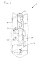
- the hinge 10 includes a main hinge body 12 pivoting with a leaf 16 about a pin 14.
- the components of the hinge 10 may be made of brass or other suitable materials.
- the hinge body 12 includes a base 18 having mounting holes 50 formed therein for mounting the hinge body 12 to a surface.
- a support or riser portion 24 extends upward from the base 18 and includes annular knuckles 20 configured to receive and surround the pin 14, as explained hereinafter.
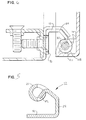
- the knuckles 20 each include an opening portion or wall opening which is cut out from the annular portion of the knuckle 20 and extending into the support portion 24.
- a retainer member or biasing means 22 is formed in the cut out portion and extends from the support portion 24 partially into the space which is enclosed by each knuckle 20, as also shown in Figure 4.
- the retainer member 22 may extend on either side of the opening for the pins.
- the leaf member 16 also includes a knuckle 28 and may be molded into a cover or other pivoting portion. It can be appreciated that many configurations and mounting methods for the leaf 16 may be utilized.
- the pin 14 includes a first end 30 with a tapered nose portion 32. At a second end 34, an enlarged pin removal portion 36 is configured to be gripped or pried to aid removal of the pin 14.
- Proximate the first end 30 are a first annular groove 38 and a second annular groove 40.
- the first annular groove includes a pair of tapering sides 42.
- the second annular groove 40 includes a straight side 44 nearer the first end 30 and extending radially outward.
- a second side 46 tapers radially outward nearer the second end 34.
- the hinge pin 14 inserts through the knuckles 20 and 28 to pivotally connect the hinge body portion 12 to the leaf portion 16.
- the first end 30 engages the retainer member 22.
- the tapered portion 32 forces the retainer portion 22 outward and allows the pin to slide by.
- the retainer member 22 slides over the first annular groove 38 and its tapered side 42.
- the retainer 22 then slides over the second annular groove 40, as the retainer 22 slides over the straight side 44.
- the pin 14 As the pin 14 slides through the leaf knuckle 28, the pin 14 engages the second knuckle 20. As with the first knuckle engaged, the retainer member 22 slides over the annular groove 38. At this point, the pin 14 is fully engaged, as shown in Figure 1. The retainer member 22 at the first end of the pin 30 rests in the annular groove 38. The pin 14 is prevented from being further inserted through the hinge body 12 as the removal portion 36 abuts the knuckle 20.
- the pin 14 may not be retracted further at this point as the retainer member 22 is resting in the second annular groove 40. Further pressure forces the side of the retainer member 22 against the straight side 44 of the second annular groove 40. This prevents further retracting movement of the pin 14 relative to the retainer 14. However, as the retainer member 22 is resting in the annular groove 40, the biasing force of the member is sufficient to retain the pin 14 from sliding in either direction.
Landscapes
- Engineering & Computer Science (AREA)
- Mechanical Engineering (AREA)
- Hinges (AREA)
Claims (8)
- Charnière (10) comprenant:caractérisée par les articulations (20) qui sont supportées en étant espacées de la base (18) et dans lesquelles une partie de sollicitation (22) de la partie montante (24) est solidaire du corps de charnière (12) et s'étend dans la partie ouverte et partiellement dans l'ouverture tubulaire, de sorte que la partie de sollicitation (22) s'étend dans les rainures (38, 40) quand les rainures (38, 40) s'alignent avec une partie de sollicitation (22) correspondante.un corps de charnière (12) comportant une base (18) et une partie montante (24), la partie montante partant vers le haut de la base et supportant une pluralité d'articulations annulaires (20) formant des ouvertures tubulaires alignées,une broche (14) configurée de façon à s'ajuster à travers les ouvertures tubulaires, comprenant une première extrémité conique (30) et une première rainure annulaire (38) formée dans la broche à proximité de l'extrémité conique, la première rainure annulaire (38) comportant des côtés coniques (42), et une seconde rainure (40) comportant un premier côté droit (44) plus près de l'extrémité conique et un côté conique opposé (46), chaque articulation présentant une paroi définissant une partie ouverte,
- Charnière (10) selon la revendication 1, comprenant en outre des moyens de montage (50) pour monter le corps de charnière (12) sur une surface.
- Charnière (10) selon la revendication 1, dans laquelle la broche (14) comprend en outre des moyens (36) de retrait de broche pour retirer la broche de la charnière.
- Charnière (10) selon la revendication 1, dans laquelle la partie de sollicitation (22) est configurée de façon à coulisser sur les côtés coniques (42, 46) de rainure et à être en appui sur le côté droit (44) de la rainure (40).
- Charnière (10) selon la revendication 4, comprenant en outre des moyens (36) de retrait de broche à une seconde extrémité de la broche (14), dans laquelle les moyens de retrait sont plus larges que les ouvertures tubulaires.
- Charnière (10) selon la revendication 1, comprenant en outre une partie à feuille comportant une articulation (28) entre deux articulations (20) du corps de charnière (12) configurée de façon à recevoir la broche (14).
- Corps de charnière (12) comprenant une base (18) et une partie montante (24), la partie montante (24) partant vers le haut de la partie de base et supportant une pluralité d'articulations (20), lesdites articulations formant des ouvertures tubulaires alignées dans lesquelles chacune desdites articulations a une paroi d'articulation y définissant une ouverture de paroi, caractérisé en ce que les articulations (20) sont espacées de la base à l'aide de la partie montante (24), et dans lequel chaque articulation (20) a une partie de sollicitation (22) solidaire du corps de charnière (12) et à proximité de chaque ouverture de paroi s'étendant de la partie montante (24) partiellement jusque dans réouverture tubulaire.
- Corps de charnière (12) selon la revendication 7, comprenant en outre un élément formant feuille (16) comportant une articulation de feuille (28) entre deux articulations du corps de charnière configurée de façon à recevoir une broche (14).
Applications Claiming Priority (3)
| Application Number | Priority Date | Filing Date | Title |
|---|---|---|---|
| US15512393A | 1993-11-19 | 1993-11-19 | |
| US155123 | 1993-11-19 | ||
| PCT/US1994/013302 WO1995014149A1 (fr) | 1993-11-19 | 1994-11-18 | Systeme de charniere |
Publications (2)
| Publication Number | Publication Date |
|---|---|
| EP0729541A1 EP0729541A1 (fr) | 1996-09-04 |
| EP0729541B1 true EP0729541B1 (fr) | 1998-04-15 |
Family
ID=22554186
Family Applications (1)
| Application Number | Title | Priority Date | Filing Date |
|---|---|---|---|
| EP95901940A Expired - Lifetime EP0729541B1 (fr) | 1993-11-19 | 1994-11-18 | Systeme de charniere |
Country Status (6)
| Country | Link |
|---|---|
| US (1) | US5666695A (fr) |
| EP (1) | EP0729541B1 (fr) |
| JP (1) | JPH09511033A (fr) |
| CA (1) | CA2176242A1 (fr) |
| DE (1) | DE69409667T2 (fr) |
| WO (1) | WO1995014149A1 (fr) |
Families Citing this family (49)
| Publication number | Priority date | Publication date | Assignee | Title |
|---|---|---|---|---|
| GB9526510D0 (en) * | 1995-12-23 | 1996-02-28 | Ihw Ltd | Hinge assembly for a vehicle door |
| DE19632027A1 (de) * | 1996-08-08 | 1998-02-12 | Scharwaechter Gmbh Co Kg | Trennbares Kraftwagentürscharnier |
| AU723760B2 (en) * | 1997-04-25 | 2000-09-07 | Torqmaster Inc. | Friction hinge with retention finger |
| US5943738A (en) * | 1998-01-06 | 1999-08-31 | Torqmaster, Inc. | Friction hinge with retention finger |
| DE29715007U1 (de) * | 1997-08-22 | 1997-10-16 | Usine Métallurgique Altkirch S.A., Altkirch | Stangen-Türband-Garnitur |
| US6068308A (en) | 1998-03-13 | 2000-05-30 | Austin Hardware, Inc. | Latch assembly |
| CA2237976A1 (fr) | 1998-06-15 | 1999-12-15 | Christian Guillemette | Dispositif d'articulation verrouillable |
| US5931104A (en) * | 1998-06-22 | 1999-08-03 | Horn; William A. | Pivotal hinge security safe |
| US5971515A (en) * | 1998-06-22 | 1999-10-26 | Baker; Steven J. | Protected internal hinge for security safe |
| US6502872B1 (en) | 1998-10-09 | 2003-01-07 | Austin Hardware, Inc. | Latch assembly |
| US6354119B1 (en) | 1999-11-24 | 2002-03-12 | Austin Hardware, Inc. | Handle and lock |
| JP4014344B2 (ja) * | 2000-01-05 | 2007-11-28 | 株式会社ジャムコ | ヒンジ部材 |
| US6393662B1 (en) * | 2000-02-22 | 2002-05-28 | Hon Hai Precision Ind. Co., Ltd. | Lubricated hinge device |
| US6315154B1 (en) * | 2000-03-15 | 2001-11-13 | Delta Consolidated Industries | Double-wall blow-molded article with pinned hinge |
| US6684457B2 (en) * | 2000-05-25 | 2004-02-03 | Liebert Corporation | Adjustable and reversible hinge assembly |
| DE10030591C1 (de) * | 2000-06-21 | 2002-02-21 | Edscha Ag | Scharnier |
| US6604798B1 (en) | 2000-08-10 | 2003-08-12 | Integra Enclosures | Enclosure for securing components |
| US6952940B2 (en) | 2000-10-23 | 2005-10-11 | Allegis Corporation | Double lock T-handle assembly |
| US6532778B2 (en) | 2000-10-23 | 2003-03-18 | Allegis Corporation | Double lock T-handle assembly |
| US6438800B1 (en) * | 2001-01-22 | 2002-08-27 | General Electric Company | Door hinge assembly for an electrical appliance enclosure |
| AU150813S (en) | 2001-09-11 | 2003-02-24 | Viscount Plastics Australia Pty Ltd | A hinge pin |
| US7599842B2 (en) * | 2003-01-16 | 2009-10-06 | Genworth Financial, Inc. | Systems and methods for assignment of sales leads |
| TW200517572A (en) * | 2003-10-17 | 2005-06-01 | Brush & Co John D | Internal hinge for fire resistant safe |
| US20050103797A1 (en) * | 2003-11-13 | 2005-05-19 | Monoflo International, Inc. | Plastic container including plastic hinge assembly |
| US20050235461A1 (en) * | 2004-03-31 | 2005-10-27 | George Timothy V | Compression finial |
| US7100243B1 (en) | 2005-06-07 | 2006-09-05 | Platzke Mason F | Gate hinge with locking pin |
| ITPD20050226A1 (it) * | 2005-07-21 | 2007-01-22 | Alutec Srl | Cerniera per serramenti |
| US8226130B2 (en) | 2005-12-09 | 2012-07-24 | Industrilås i NässjöAB | Control roller mechanism-activator |
| US7761958B2 (en) * | 2005-12-09 | 2010-07-27 | Allegris Corporation | Hinge and latch mechanism |
| DE102007019939B3 (de) * | 2007-04-27 | 2008-09-18 | Simonswerk, Gmbh | Türband und Verfahren zur Herstellung eines Türbandes |
| US20080295285A1 (en) * | 2007-05-31 | 2008-12-04 | Hoffman Enclosures, Inc | Hinge pin for enclosure |
| US8714667B2 (en) * | 2007-10-01 | 2014-05-06 | Hoffman Enclosures, Inc. | Configurable enclosure for electronics components |
| US7819443B2 (en) * | 2007-11-19 | 2010-10-26 | Ventfabrics, Inc. | Door latch assembly |
| CN201335093Y (zh) * | 2008-12-04 | 2009-10-28 | 康准电子科技(昆山)有限公司 | 枢纽器 |
| CN201439667U (zh) * | 2009-05-26 | 2010-04-21 | 国基电子(上海)有限公司 | 铰链及使用所述铰链的电子装置 |
| CN102094895A (zh) * | 2009-12-11 | 2011-06-15 | 康准电子科技(昆山)有限公司 | 枢纽器 |
| US8464396B2 (en) | 2011-09-16 | 2013-06-18 | Hoffman Enclosures Inc. | Removable hidden hinge pin |
| EP2710933B1 (fr) * | 2012-09-21 | 2017-06-07 | Burg-Wächter Kg | Dispositif de réception d'envois de courriers, de colis et/ou de marchandises |
| US10119322B2 (en) * | 2015-08-27 | 2018-11-06 | Ellenby Technologies, Inc. | Electronic safes and hinge mechanisms for electronic safe |
| US10544611B2 (en) * | 2016-03-17 | 2020-01-28 | Hubbell Incorporated | Removable hinge assemblies |
| US10442580B2 (en) | 2016-11-10 | 2019-10-15 | Steven Murrill | Chemical storage container with locking hinge |
| DE102017100644B4 (de) * | 2017-01-13 | 2018-08-30 | Solarlux Gmbh | Lösbare Scharnieranordnung mit Fehlbediensperre |
| DE102017108586B3 (de) * | 2017-04-21 | 2017-12-28 | Rittal Gmbh & Co. Kg | Scharnier für ein Schaltschrankgehäuse sowie ein entsprechendes Schaltschrankgehäuse und Montageverfahren |
| KR102154924B1 (ko) * | 2019-03-08 | 2020-09-10 | 나성호 | 변위가능한 힌지유닛 |
| DE102019118758B3 (de) * | 2019-07-11 | 2020-10-08 | Dirak Dieter Ramsauer Konstruktionselemente Gmbh | Scharnier und System zum lösbaren Verbinden einer Tür mit einem Rahmen |
| US11473357B2 (en) * | 2021-03-09 | 2022-10-18 | Fca Us Llc | Hinge for a removable vehicle door |
| US11927042B2 (en) | 2021-07-30 | 2024-03-12 | Airbus Americas, Inc. | Quick-release hinge devices, systems and methods |
| TWI812535B (zh) * | 2022-11-04 | 2023-08-11 | 富世達股份有限公司 | 鉸鏈 |
| US12460462B2 (en) | 2023-02-16 | 2025-11-04 | Ellenby Technologies, Inc. | Secure vault apparatus |
Family Cites Families (25)
| Publication number | Priority date | Publication date | Assignee | Title |
|---|---|---|---|---|
| US93058A (en) * | 1869-07-27 | Improved hinge | ||
| NL278783A (fr) * | ||||
| US713338A (en) * | 1902-08-28 | 1902-11-11 | Napoleon Paquette | Hinge. |
| US1728433A (en) * | 1924-07-21 | 1929-09-17 | John L Mohun | Journal box |
| US1754013A (en) * | 1928-01-12 | 1930-04-08 | Fisher Joseph | Hinge |
| US1824886A (en) * | 1929-06-19 | 1931-09-29 | Stanley Works | Hinge construction |
| FR716946A (fr) * | 1931-05-12 | 1931-12-30 | Charnière | |
| US1979894A (en) * | 1932-06-18 | 1934-11-06 | Reading Hardware Corp | Butt hinge construction |
| US2817871A (en) * | 1955-07-18 | 1957-12-31 | Stanley Works | Hinge |
| US2997734A (en) * | 1955-11-23 | 1961-08-29 | Herbert A Dyer | Hinge |
| US2937399A (en) * | 1957-10-14 | 1960-05-24 | Griffin Mfg Company | Hinge |
| US3013297A (en) * | 1958-01-06 | 1961-12-19 | Stanley Works | Hinge having pintle retaining means |
| US3068508A (en) * | 1959-05-04 | 1962-12-18 | M And H Ind | Hinge construction |
| US3135013A (en) * | 1961-03-10 | 1964-06-02 | Stanley Works | Hinge with pin retaining means |
| US3621512A (en) * | 1970-06-12 | 1971-11-23 | Arthur Johnson | Tamper resistant hinge |
| US3733649A (en) * | 1971-08-11 | 1973-05-22 | Ch Nagy | Tamper proof door butt hinge assembly |
| CA975417A (en) * | 1973-03-30 | 1975-09-30 | Anton Johl | Folding article of furniture |
| US3962750A (en) * | 1975-04-07 | 1976-06-15 | Gott Manufacturing Co., Inc. | Hinge construction |
| DE2623140A1 (de) * | 1976-05-22 | 1977-12-01 | Ver Baubeschlag Gretsch Co | Gelenkverbindung |
| US4475266A (en) * | 1979-05-24 | 1984-10-09 | The Stanley Works | Non-handed two knuckle hinge |
| US4455711A (en) * | 1981-07-20 | 1984-06-26 | Hartwell Corporation | Hinge having a laterally outwardly extending flat spring |
| US4413449A (en) * | 1982-01-25 | 1983-11-08 | Faye Lloyd H | Motorized system for cleaning drain troughs |
| DE3314753A1 (de) * | 1983-04-23 | 1984-10-25 | Simonswerk GmbH, 4840 Rheda-Wiedenbrück | Mehrteiliges scharnier |
| US4603452A (en) * | 1985-01-22 | 1986-08-05 | General Dynamics Corporation | Detachable hinge with conveniently releasable hinge flaps |
| US5355559A (en) * | 1993-04-26 | 1994-10-18 | Amerock Corporation | Hinge for inset doors |
-
1994
- 1994-11-18 EP EP95901940A patent/EP0729541B1/fr not_active Expired - Lifetime
- 1994-11-18 JP JP7514605A patent/JPH09511033A/ja active Pending
- 1994-11-18 DE DE69409667T patent/DE69409667T2/de not_active Expired - Fee Related
- 1994-11-18 CA CA002176242A patent/CA2176242A1/fr not_active Abandoned
- 1994-11-18 WO PCT/US1994/013302 patent/WO1995014149A1/fr not_active Ceased
-
1995
- 1995-11-16 US US08/558,412 patent/US5666695A/en not_active Expired - Fee Related
Also Published As
| Publication number | Publication date |
|---|---|
| JPH09511033A (ja) | 1997-11-04 |
| WO1995014149A1 (fr) | 1995-05-26 |
| DE69409667T2 (de) | 1998-09-24 |
| CA2176242A1 (fr) | 1995-05-26 |
| DE69409667D1 (de) | 1998-05-20 |
| EP0729541A1 (fr) | 1996-09-04 |
| US5666695A (en) | 1997-09-16 |
Similar Documents
| Publication | Publication Date | Title |
|---|---|---|
| EP0729541B1 (fr) | Systeme de charniere | |
| JP7282931B2 (ja) | 土壌作業機器用摩耗部品 | |
| US5782569A (en) | Molded binder assembly | |
| CA1286862C (fr) | Charniere amovible pour portiere de vehicule automobile | |
| CA2237976A1 (fr) | Dispositif d'articulation verrouillable | |
| US5161759A (en) | Wire bundle retainer | |
| JP2003534935A (ja) | 調整スパナの取手のための取り替えグリップ | |
| US4965889A (en) | Cover for a toilet bowl | |
| US4864692A (en) | Hinge with axial pin locking system for doors or windows | |
| US4715090A (en) | Demountable hinges | |
| US20010016967A1 (en) | Hinge | |
| EP0794307B1 (fr) | Une charnière pour portes et fenêtres métalliques | |
| US6178561B1 (en) | Safety goggles having a lens frame force-fitted in a primary frame | |
| JP2001504930A (ja) | 制御ケーブルのためのシースターミナル | |
| EP0748716A3 (fr) | Articulation pour un siège arrière de véhicules | |
| EP0873706B1 (fr) | Système d'étagères | |
| US4261266A (en) | Extensible table | |
| GB2180884A (en) | Lift-off hinge assembly | |
| AU4864197A (en) | Assembly component and object with integrated assembly component | |
| US5964480A (en) | Document folder assembly | |
| US6619643B1 (en) | Clamping device | |
| GB2204910A (en) | Lift-off hinge assembly | |
| EP1155651B1 (fr) | Système de fixation pour tampons de siège de toilette | |
| EP4296146A1 (fr) | Dispositif de verrouillage/déverrouillage pour garde-boue de véhicule et ensemble garde-boue associé | |
| EP0033348A1 (fr) | Reliures de livres et leur suspension d'amarrage |
Legal Events
| Date | Code | Title | Description |
|---|---|---|---|
| PUAI | Public reference made under article 153(3) epc to a published international application that has entered the european phase |
Free format text: ORIGINAL CODE: 0009012 |
|
| 17P | Request for examination filed |
Effective date: 19960618 |
|
| AK | Designated contracting states |
Kind code of ref document: A1 Designated state(s): DE FR GB IT |
|
| GRAG | Despatch of communication of intention to grant |
Free format text: ORIGINAL CODE: EPIDOS AGRA |
|
| 17Q | First examination report despatched |
Effective date: 19970219 |
|
| GRAG | Despatch of communication of intention to grant |
Free format text: ORIGINAL CODE: EPIDOS AGRA |
|
| GRAH | Despatch of communication of intention to grant a patent |
Free format text: ORIGINAL CODE: EPIDOS IGRA |
|
| GRAH | Despatch of communication of intention to grant a patent |
Free format text: ORIGINAL CODE: EPIDOS IGRA |
|
| GRAA | (expected) grant |
Free format text: ORIGINAL CODE: 0009210 |
|
| ITF | It: translation for a ep patent filed | ||
| AK | Designated contracting states |
Kind code of ref document: B1 Designated state(s): DE FR GB IT |
|
| REF | Corresponds to: |
Ref document number: 69409667 Country of ref document: DE Date of ref document: 19980520 |
|
| ET | Fr: translation filed | ||
| PLBE | No opposition filed within time limit |
Free format text: ORIGINAL CODE: 0009261 |
|
| STAA | Information on the status of an ep patent application or granted ep patent |
Free format text: STATUS: NO OPPOSITION FILED WITHIN TIME LIMIT |
|
| 26N | No opposition filed | ||
| PGFP | Annual fee paid to national office [announced via postgrant information from national office to epo] |
Ref country code: GB Payment date: 20001004 Year of fee payment: 7 |
|
| PGFP | Annual fee paid to national office [announced via postgrant information from national office to epo] |
Ref country code: FR Payment date: 20001107 Year of fee payment: 7 |
|
| PGFP | Annual fee paid to national office [announced via postgrant information from national office to epo] |
Ref country code: DE Payment date: 20001124 Year of fee payment: 7 |
|
| PG25 | Lapsed in a contracting state [announced via postgrant information from national office to epo] |
Ref country code: GB Free format text: LAPSE BECAUSE OF NON-PAYMENT OF DUE FEES Effective date: 20011118 |
|
| REG | Reference to a national code |
Ref country code: GB Ref legal event code: IF02 |
|
| PG25 | Lapsed in a contracting state [announced via postgrant information from national office to epo] |
Ref country code: DE Free format text: LAPSE BECAUSE OF NON-PAYMENT OF DUE FEES Effective date: 20020702 |
|
| GBPC | Gb: european patent ceased through non-payment of renewal fee |
Effective date: 20011118 |
|
| PG25 | Lapsed in a contracting state [announced via postgrant information from national office to epo] |
Ref country code: FR Free format text: LAPSE BECAUSE OF NON-PAYMENT OF DUE FEES Effective date: 20020730 |
|
| REG | Reference to a national code |
Ref country code: FR Ref legal event code: ST |
|
| REG | Reference to a national code |
Ref country code: FR Ref legal event code: ST |
|
| PG25 | Lapsed in a contracting state [announced via postgrant information from national office to epo] |
Ref country code: IT Free format text: LAPSE BECAUSE OF NON-PAYMENT OF DUE FEES Effective date: 20051118 |