EP0729547B1 - Starthilfevorrichtung, insbesondere für dieselmotoren - Google Patents
Starthilfevorrichtung, insbesondere für dieselmotoren Download PDFInfo
- Publication number
- EP0729547B1 EP0729547B1 EP95926841A EP95926841A EP0729547B1 EP 0729547 B1 EP0729547 B1 EP 0729547B1 EP 95926841 A EP95926841 A EP 95926841A EP 95926841 A EP95926841 A EP 95926841A EP 0729547 B1 EP0729547 B1 EP 0729547B1
- Authority
- EP
- European Patent Office
- Prior art keywords
- solid electrolyte
- electrode
- starting aid
- aid system
- oxygen
- Prior art date
- Legal status (The legal status is an assumption and is not a legal conclusion. Google has not performed a legal analysis and makes no representation as to the accuracy of the status listed.)
- Expired - Lifetime
Links
- 239000007784 solid electrolyte Substances 0.000 claims description 29
- 229910052760 oxygen Inorganic materials 0.000 claims description 16
- 239000001301 oxygen Substances 0.000 claims description 16
- 238000002347 injection Methods 0.000 claims description 15
- 239000007924 injection Substances 0.000 claims description 15
- QVGXLLKOCUKJST-UHFFFAOYSA-N atomic oxygen Chemical compound [O] QVGXLLKOCUKJST-UHFFFAOYSA-N 0.000 claims description 14
- 238000002485 combustion reaction Methods 0.000 claims description 7
- 239000000446 fuel Substances 0.000 claims description 5
- MCMNRKCIXSYSNV-UHFFFAOYSA-N Zirconium dioxide Chemical compound O=[Zr]=O MCMNRKCIXSYSNV-UHFFFAOYSA-N 0.000 claims description 3
- 230000002093 peripheral effect Effects 0.000 claims 1
- 239000000919 ceramic Substances 0.000 description 4
- 239000000203 mixture Substances 0.000 description 3
- -1 Oxygen ion Chemical class 0.000 description 2
- 238000010438 heat treatment Methods 0.000 description 2
- MYMOFIZGZYHOMD-UHFFFAOYSA-N Dioxygen Chemical compound O=O MYMOFIZGZYHOMD-UHFFFAOYSA-N 0.000 description 1
- 230000015572 biosynthetic process Effects 0.000 description 1
- 239000004020 conductor Substances 0.000 description 1
- 239000002283 diesel fuel Substances 0.000 description 1
- 229910001882 dioxygen Inorganic materials 0.000 description 1
- 238000010292 electrical insulation Methods 0.000 description 1
- RVTZCBVAJQQJTK-UHFFFAOYSA-N oxygen(2-);zirconium(4+) Chemical compound [O-2].[O-2].[Zr+4] RVTZCBVAJQQJTK-UHFFFAOYSA-N 0.000 description 1
- 238000005086 pumping Methods 0.000 description 1
- 238000007789 sealing Methods 0.000 description 1
Images

Classifications
-
- F—MECHANICAL ENGINEERING; LIGHTING; HEATING; WEAPONS; BLASTING
- F02—COMBUSTION ENGINES; HOT-GAS OR COMBUSTION-PRODUCT ENGINE PLANTS
- F02N—STARTING OF COMBUSTION ENGINES; STARTING AIDS FOR SUCH ENGINES, NOT OTHERWISE PROVIDED FOR
- F02N19/00—Starting aids for combustion engines, not otherwise provided for
- F02N19/001—Arrangements thereof
-
- F—MECHANICAL ENGINEERING; LIGHTING; HEATING; WEAPONS; BLASTING
- F02—COMBUSTION ENGINES; HOT-GAS OR COMBUSTION-PRODUCT ENGINE PLANTS
- F02P—IGNITION, OTHER THAN COMPRESSION IGNITION, FOR INTERNAL-COMBUSTION ENGINES; TESTING OF IGNITION TIMING IN COMPRESSION-IGNITION ENGINES
- F02P19/00—Incandescent ignition, e.g. during starting of internal combustion engines; Combination of incandescent and spark ignition
- F02P19/02—Incandescent ignition, e.g. during starting of internal combustion engines; Combination of incandescent and spark ignition electric, e.g. layout of circuits of apparatus having glowing plugs
-
- F—MECHANICAL ENGINEERING; LIGHTING; HEATING; WEAPONS; BLASTING
- F02—COMBUSTION ENGINES; HOT-GAS OR COMBUSTION-PRODUCT ENGINE PLANTS
- F02B—INTERNAL-COMBUSTION PISTON ENGINES; COMBUSTION ENGINES IN GENERAL
- F02B2275/00—Other engines, components or details, not provided for in other groups of this subclass
- F02B2275/16—Indirect injection
-
- F—MECHANICAL ENGINEERING; LIGHTING; HEATING; WEAPONS; BLASTING
- F02—COMBUSTION ENGINES; HOT-GAS OR COMBUSTION-PRODUCT ENGINE PLANTS
- F02B—INTERNAL-COMBUSTION PISTON ENGINES; COMBUSTION ENGINES IN GENERAL
- F02B3/00—Engines characterised by air compression and subsequent fuel addition
- F02B3/06—Engines characterised by air compression and subsequent fuel addition with compression ignition
-
- Y—GENERAL TAGGING OF NEW TECHNOLOGICAL DEVELOPMENTS; GENERAL TAGGING OF CROSS-SECTIONAL TECHNOLOGIES SPANNING OVER SEVERAL SECTIONS OF THE IPC; TECHNICAL SUBJECTS COVERED BY FORMER USPC CROSS-REFERENCE ART COLLECTIONS [XRACs] AND DIGESTS
- Y02—TECHNOLOGIES OR APPLICATIONS FOR MITIGATION OR ADAPTATION AGAINST CLIMATE CHANGE
- Y02T—CLIMATE CHANGE MITIGATION TECHNOLOGIES RELATED TO TRANSPORTATION
- Y02T10/00—Road transport of goods or passengers
- Y02T10/10—Internal combustion engine [ICE] based vehicles
- Y02T10/12—Improving ICE efficiencies
Definitions
- the invention relates to a starting aid device for diesel engines after the kind of Main claim.
- Jump start devices known, such as Glow plugs or flame candles.
- the Jump start devices are in the combustion chamber or in the Intake pipe of diesel engines arranged and with them the by means of an injection jet into the combustion chamber or Diesel fuel introduced into the intake pipe for ignition brought.
- the ignition temperature is determined by glow plugs achieved an electrically heated glow pencil, the Temperature can be over 1000 ° C.
- the jump start device according to the invention with the has characteristic features of the main claim in contrast, the advantage that the ignition temperature is lowered can be and at the same time easier ignition of the Air / fuel mixture is possible. This ensures that the engine is more even on cold start Exhibits run-up behavior.
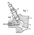
- Figure 1 shows a combustion chamber with a prechamber a diesel engine
- Figure 2 shows an oxygen pump cell in Finger design
- Figure 3 with an oxygen pump cell planar solid electrolyte body
- Figure 4 is a cross section through the solid electrolyte body according to FIG. 3.
- a diesel engine with an engine block 11 has a combustion chamber 12 with a prechamber 13.
- a Injection valve 14 with an injection jet 15 such used that the injection jet 15 in the prechamber 13th is led.
- the antechamber 13 there is still one Jumper 16 positioned up to the Edge zone of the injection jet 15 is sufficient.
- the starting aid device 16 is an oxygen pump cell 18 which works on the basis of an oxygen ion-conducting solid electrolyte.
- Zirconium dioxide stabilized with Y 2 O 3 for example, is used as the solid electrolyte ceramic.
- the solid electrolyte ceramic can, according to FIG. 2, be constructed from a tubular solid electrolyte body 20 which is closed on one side and has a finger design or, according to FIGS. 3 and 4, as a platelet-shaped solid electrolyte body 30.
- the tubular solid electrolyte body 20 according to FIG. 1 is shown in FIG a metallic housing 23 used and has on it outer surface of a first electrode 21 and on its inner surface of a second electrode 22.
- the electrodes 21, 22 are provided with conductor tracks, the electrode 21 with the housing 23 and the electrode 22 with a Contact part 24 is contacted.
- a rod-shaped heating element 25 arranged inside the Solid electrolyte body 20 .
- the platelet-shaped solid electrolyte body 30 according to FIG. 3 is also in a metallic housing 33 Holding means 34 and sealing means 35 attached.
- Solid electrolyte body 30 according to FIG. 4 for example from a first solid electrolyte film 36, a second Solid electrolyte sheet 37 and a third solid electrolyte sheet 38.
- a channel 39 is in the second solid electrolyte film 37 stamped, which is open on the housing side and with the Atmosphere.
- On the injection jet side Channel 39 is closed at the end.
- On the first Solid electrolyte sheet 36 is an outer first electrode 31 and a second electrode 32 positioned in channel 39 arranged.
- a heater 41 embedded In the third solid electrolyte film 38 is in a electrical insulation 40 a heater 41 embedded.
- the heater element 25 of the tubular solid electrolyte body 20 and the heater 41 of the plate-shaped Solid electrolyte body 30 serve to the ceramic of Solid electrolyte body to the corresponding Bring operating temperature to the formation of a Oxygen ion conduction is necessary.
- the Oxygen ion conduction and thus the oxygen transport already set at a temperature of around 300 ° C a. It is expedient to use the heating devices 25, 41 at the same time the ignition temperature for the Realize fuel / air mixture.
- a pump voltage of, for example 800 mV applied is applied to the electrodes 21, 31 each as an anode and in connection with the atmosphere standing electrodes 22, 32 each connected as a cathode are.
- This causes molecular oxygen to escape Atmosphere using the oxygen pumping phenomenon in Solid electrolyte ceramics from the one connected as cathode Electrode 22, 32 to the electrode connected as an anode 21.31.
Landscapes
- Engineering & Computer Science (AREA)
- Chemical & Material Sciences (AREA)
- Combustion & Propulsion (AREA)
- Mechanical Engineering (AREA)
- General Engineering & Computer Science (AREA)
- Combustion Methods Of Internal-Combustion Engines (AREA)
Description
Claims (8)
- Starthilfevorrichtung für einen Dieselmotor mit einer in einem Verbrennungsraum oder in einem Ansaugrohr angeordneten Starthilfeeinrichtung, welche einen in den Verbrennungsraum oder das Ansaugrohr eingeleiteten Einspritzstrahl eines Kraftstoffs in einen zündfähigen Zustand bringt, gekennzeichnet durch eine auf der Basis eines sauerstoffionenleitenden Festelektrolyten arbeitende Sauerstoff-Pumpzelle (18), mit welcher Sauerstoff zumindest in die Randzone des Einspritzstrahls (15) gepumpt wird.
- Starthilfevorrichtung nach Anspruch 1, dadurch gekennzeichnet, daß die Pumpzelle (18) eine erste Elektrode (21, 31) und eine zweite Elektrode (22, 32) aufweist, wobei zumindest eine der Elektroden (21, 31) sich im Bereich des Einspritzstrahls (15) befindet, und daß eine Pumpspannung an die Elekroden (21, 22, 31, 32) derart angelegt ist, daß Sauerstoff von der einen Elektrode zu der im Einspritzstrahl (15) angeordneten Elektrode gepumpt wird.
- Starthilfevorrichtung nach Anspruch 2, dadurch gekennzeichnet, daß die andere Elektrode (22, 32) mit der Atmosphäre in Verbindung steht, so daß Sauerstoff aus der Atmosphäre in den Verbrennungsraum (12, 13) gepumpt wird.
- Starthilfevorrichtung nach Anspruch 3, dadurch gekennzeichnet, daß die Pumpzelle (18) einen rohrförmigen Festelektrolytkörper (20) aufweist, der am einspritzstrahlseitigen Ende geschlossen ist und mit seinem offenen Ende mit der Atmosphäre in Verbindung steht.
- Starthilfevorrichtung nach Anspruch 2, dadurch gekennzeichnet, daß die Pumpzelle (18) einen plättchenförmigen Festelektrolytkörper (30) aufweist, bei dem die eine Elektrode (31) im Einspritzstrahl (15) und die andere Elektrode (32) vom Einspritzstrahl (15) abgewandt auf dem plättchenförmigen Festelektrolytkörper (30) angeordnet ist.
- Starthilfevorrichtung nach Anspruch 5, dadurch gekennzeichnet, daß der Festelektrolytkörper (30) einen mit der Atmosphäre in Verbindung stehenden Kanal (39) aufweist, in dem die andere Elektrode (32) angeordnet ist.
- Starthilfevorrichtung nach Anspruch 4, 5 oder 6, dadurch gekennzeichnet, daß der Festelektrolytkörper (20, 30) aus stabilisiertem ZrO2 besteht.
- Starthilfeeinrichtung nach Anspruch 1, dadurch gekennzeichnet, daß die Pumpzelle (18) eine Heizeinrichtung (25, 41) aufweist, mit der sowohl die Betriebstemperatur der Pumpzelle (18) als auch die Zündtemperatur des Kraftstoffs im Einspritzstrahl (15) einstellbar ist.
Applications Claiming Priority (3)
| Application Number | Priority Date | Filing Date | Title |
|---|---|---|---|
| DE4431477 | 1994-09-03 | ||
| DE4431477A DE4431477C2 (de) | 1994-09-03 | 1994-09-03 | Starthilfevorrichtung, insbesondere für einen Dieselmotor |
| PCT/DE1995/001010 WO1996007823A1 (de) | 1994-09-03 | 1995-08-03 | Starthilfevorrichtung, insbesondere für dieselmotoren |
Publications (2)
| Publication Number | Publication Date |
|---|---|
| EP0729547A1 EP0729547A1 (de) | 1996-09-04 |
| EP0729547B1 true EP0729547B1 (de) | 1998-12-23 |
Family
ID=6527385
Family Applications (1)
| Application Number | Title | Priority Date | Filing Date |
|---|---|---|---|
| EP95926841A Expired - Lifetime EP0729547B1 (de) | 1994-09-03 | 1995-08-03 | Starthilfevorrichtung, insbesondere für dieselmotoren |
Country Status (5)
| Country | Link |
|---|---|
| US (1) | US5678518A (de) |
| EP (1) | EP0729547B1 (de) |
| JP (1) | JPH09505129A (de) |
| DE (2) | DE4431477C2 (de) |
| WO (1) | WO1996007823A1 (de) |
Families Citing this family (5)
| Publication number | Priority date | Publication date | Assignee | Title |
|---|---|---|---|---|
| US7469662B2 (en) * | 1999-03-23 | 2008-12-30 | Thomas Engine Company, Llc | Homogeneous charge compression ignition engine with combustion phasing |
| US6585809B1 (en) * | 2002-07-12 | 2003-07-01 | Komad Parsa | Continuous gas separation in an open system |
| US7318858B2 (en) * | 2002-07-12 | 2008-01-15 | Parsa Investment, L.P. | Gas separator for providing an oxygen-enriched stream |
| US6895945B2 (en) * | 2002-07-12 | 2005-05-24 | Parsa Investments, L.P. | System and method for conditioning of intake air for an internal combustion engine |
| US8925518B1 (en) * | 2014-03-17 | 2015-01-06 | Woodward, Inc. | Use of prechambers with dual fuel source engines |
Family Cites Families (11)
| Publication number | Priority date | Publication date | Assignee | Title |
|---|---|---|---|---|
| JPS5346084A (en) * | 1976-10-08 | 1978-04-25 | Nissan Motor | Oxygen sensor |
| US4189355A (en) * | 1976-12-02 | 1980-02-19 | Nissan Motor Company, Limited | Method for detection of fluctuation in air/fuel ratio of air-fuel mixture fed to internal combustion engine |
| DE2805133C2 (de) * | 1978-02-07 | 1984-05-17 | Volkswagenwerk Ag, 3180 Wolfsburg | Luftverdichtende selbstzündende Brennkraftmaschine |
| US4407704A (en) * | 1979-12-04 | 1983-10-04 | Ngk Insulators, Ltd. | Oxygen concentration detector and a method of detecting oxygen concentration |
| JPS58162718A (ja) * | 1982-03-23 | 1983-09-27 | Nissan Motor Co Ltd | ディーゼルエンジン始動用点火装置 |
| DE3231122C2 (de) * | 1982-08-21 | 1994-05-11 | Bosch Gmbh Robert | Regeleinrichtung für die Gemischzusammensetzung einer Brennkraftmaschine |
| KR880000160B1 (ko) * | 1983-10-14 | 1988-03-12 | 미쓰비시전기 주식회사 | 기관의 공연비 제어 장치 |
| DE3918678A1 (de) * | 1989-06-08 | 1990-12-13 | Bosch Gmbh Robert | Verfahren zum einspritzen von kraftstoff in den brennraum eines dieselmotors |
| DE4014356A1 (de) * | 1990-05-04 | 1991-11-07 | Beru Werk Ruprecht Gmbh Co A | Gluehkerze |
| DE4243965A1 (de) * | 1992-12-23 | 1994-06-30 | Beru Werk Ruprecht Gmbh Co A | Flammglühanlage |
| DE4311849C2 (de) * | 1992-12-23 | 2003-04-24 | Bosch Gmbh Robert | Sensor zur Bestimmung von Gaskomponenten und/oder Gaskonzentrationen von Gasgemischen |
-
1994
- 1994-09-03 DE DE4431477A patent/DE4431477C2/de not_active Expired - Fee Related
-
1995
- 1995-08-03 JP JP8509086A patent/JPH09505129A/ja active Pending
- 1995-08-03 WO PCT/DE1995/001010 patent/WO1996007823A1/de not_active Ceased
- 1995-08-03 DE DE59504631T patent/DE59504631D1/de not_active Expired - Fee Related
- 1995-08-03 US US08/619,703 patent/US5678518A/en not_active Expired - Fee Related
- 1995-08-03 EP EP95926841A patent/EP0729547B1/de not_active Expired - Lifetime
Also Published As
| Publication number | Publication date |
|---|---|
| EP0729547A1 (de) | 1996-09-04 |
| WO1996007823A1 (de) | 1996-03-14 |
| DE4431477A1 (de) | 1996-03-14 |
| JPH09505129A (ja) | 1997-05-20 |
| DE59504631D1 (de) | 1999-02-04 |
| DE4431477C2 (de) | 1996-09-26 |
| US5678518A (en) | 1997-10-21 |
Similar Documents
| Publication | Publication Date | Title |
|---|---|---|
| DE69412939T2 (de) | Zusammenbau eines Plasmastrahl-Zünders und einer Direkteinspritzdüse | |
| DE3486042T2 (de) | Elektrochemische vorrichtung. | |
| GB1561017A (en) | Pulse-actuated fuelinjection spark plug | |
| DE2503811A1 (de) | Brennkraftmaschine | |
| DE2937048A1 (de) | Elektrochemischer messfuehler fuer die bestimmung des sauerstoffgehaltes in gasen, insbesondere in abgasen von brennkraftmaschinen | |
| DE102016218707A1 (de) | Hubkolben-Brennkraftmaschine | |
| EP0729547B1 (de) | Starthilfevorrichtung, insbesondere für dieselmotoren | |
| DE69932685T2 (de) | Glühsensor - keramische flache Platte | |
| DE3538633A1 (de) | Vorkammer mit einer anordnung zur thermischen isolierung | |
| DE102016209922A1 (de) | Vorkammerzündkerze | |
| DE10031893A1 (de) | Glühstiftkerze mit Ionenstromsensor sowie Verfahren zum Betreiben einer derartigen Glühstiftkerze | |
| DE102017204055A1 (de) | Verfahren zum Betreiben einer fremdgezündeten Hubkolben-Brennkraftmaschine und fremdgezündete Hubkolben-Brennkraftmaschine | |
| DE3230462A1 (de) | Zuendsystem einer brennkraftmaschine | |
| DE3206787A1 (de) | Zuendkerze | |
| EP3027970B1 (de) | Glühstiftkerze mit keramischem heizelement mit innenliegender kontaktierung, und herstellungsverfahren derselben | |
| DE102007050634A1 (de) | Zündkerze | |
| DE102017204806A1 (de) | Fremdgezündete Hubkolben-Brennkraftmaschine | |
| DE102014206247A1 (de) | Sensor zur Erfassung mindestens einer Eigenschaft eines Messgases in einem Messgasraum und Verfahren zum Herstellen | |
| EP0859231B1 (de) | Gasmessfühler | |
| AT413855B (de) | Brennkraftmaschine | |
| EP0213604A2 (de) | Zündvorrichtung für einen Verbrennungsmotor | |
| DE3017399A1 (de) | Brennkraftmaschine mit hauptbrennraeumen, die ueber wenigstens einen schusskanal jeweils mit einem nebenbrennraum verbunden sind | |
| WO2015090723A1 (de) | Zündkerze mit dichtung aus einem nichtleitenden material | |
| DE3616640A1 (de) | Zuendkerze mit gleitfunkenstrecke | |
| DE102023130704A1 (de) | Gassensorelement, Gassensor und Herstellungsverfahren für Gassensorelement |
Legal Events
| Date | Code | Title | Description |
|---|---|---|---|
| PUAI | Public reference made under article 153(3) epc to a published international application that has entered the european phase |
Free format text: ORIGINAL CODE: 0009012 |
|
| AK | Designated contracting states |
Kind code of ref document: A1 Designated state(s): DE FR GB IT SE |
|
| 17P | Request for examination filed |
Effective date: 19960916 |
|
| GRAG | Despatch of communication of intention to grant |
Free format text: ORIGINAL CODE: EPIDOS AGRA |
|
| 17Q | First examination report despatched |
Effective date: 19980219 |
|
| GRAG | Despatch of communication of intention to grant |
Free format text: ORIGINAL CODE: EPIDOS AGRA |
|
| GRAH | Despatch of communication of intention to grant a patent |
Free format text: ORIGINAL CODE: EPIDOS IGRA |
|
| GRAH | Despatch of communication of intention to grant a patent |
Free format text: ORIGINAL CODE: EPIDOS IGRA |
|
| GRAA | (expected) grant |
Free format text: ORIGINAL CODE: 0009210 |
|
| AK | Designated contracting states |
Kind code of ref document: B1 Designated state(s): DE FR GB IT SE |
|
| REF | Corresponds to: |
Ref document number: 59504631 Country of ref document: DE Date of ref document: 19990204 |
|
| ET | Fr: translation filed | ||
| ITF | It: translation for a ep patent filed | ||
| GBT | Gb: translation of ep patent filed (gb section 77(6)(a)/1977) |
Effective date: 19990223 |
|
| PGFP | Annual fee paid to national office [announced via postgrant information from national office to epo] |
Ref country code: GB Payment date: 19990726 Year of fee payment: 5 |
|
| PGFP | Annual fee paid to national office [announced via postgrant information from national office to epo] |
Ref country code: FR Payment date: 19990813 Year of fee payment: 5 |
|
| PGFP | Annual fee paid to national office [announced via postgrant information from national office to epo] |
Ref country code: SE Payment date: 19990818 Year of fee payment: 5 |
|
| PGFP | Annual fee paid to national office [announced via postgrant information from national office to epo] |
Ref country code: DE Payment date: 19991026 Year of fee payment: 5 |
|
| PLBE | No opposition filed within time limit |
Free format text: ORIGINAL CODE: 0009261 |
|
| STAA | Information on the status of an ep patent application or granted ep patent |
Free format text: STATUS: NO OPPOSITION FILED WITHIN TIME LIMIT |
|
| 26N | No opposition filed | ||
| PG25 | Lapsed in a contracting state [announced via postgrant information from national office to epo] |
Ref country code: GB Free format text: LAPSE BECAUSE OF NON-PAYMENT OF DUE FEES Effective date: 20000803 |
|
| PG25 | Lapsed in a contracting state [announced via postgrant information from national office to epo] |
Ref country code: SE Free format text: LAPSE BECAUSE OF NON-PAYMENT OF DUE FEES Effective date: 20000804 |
|
| GBPC | Gb: european patent ceased through non-payment of renewal fee |
Effective date: 20000803 |
|
| EUG | Se: european patent has lapsed |
Ref document number: 95926841.8 |
|
| PG25 | Lapsed in a contracting state [announced via postgrant information from national office to epo] |
Ref country code: FR Free format text: LAPSE BECAUSE OF NON-PAYMENT OF DUE FEES Effective date: 20010430 |
|
| PG25 | Lapsed in a contracting state [announced via postgrant information from national office to epo] |
Ref country code: DE Free format text: LAPSE BECAUSE OF NON-PAYMENT OF DUE FEES Effective date: 20010501 |
|
| REG | Reference to a national code |
Ref country code: FR Ref legal event code: ST |
|
| PG25 | Lapsed in a contracting state [announced via postgrant information from national office to epo] |
Ref country code: IT Free format text: LAPSE BECAUSE OF NON-PAYMENT OF DUE FEES;WARNING: LAPSES OF ITALIAN PATENTS WITH EFFECTIVE DATE BEFORE 2007 MAY HAVE OCCURRED AT ANY TIME BEFORE 2007. THE CORRECT EFFECTIVE DATE MAY BE DIFFERENT FROM THE ONE RECORDED. Effective date: 20050803 |