EP0730118A2 - Schweissrohrverbindung und Verfahren zu ihrer Herstellung - Google Patents
Schweissrohrverbindung und Verfahren zu ihrer Herstellung Download PDFInfo
- Publication number
- EP0730118A2 EP0730118A2 EP96301207A EP96301207A EP0730118A2 EP 0730118 A2 EP0730118 A2 EP 0730118A2 EP 96301207 A EP96301207 A EP 96301207A EP 96301207 A EP96301207 A EP 96301207A EP 0730118 A2 EP0730118 A2 EP 0730118A2
- Authority
- EP
- European Patent Office
- Prior art keywords
- fitting
- wire
- groove
- lead
- heating wire
- Prior art date
- Legal status (The legal status is an assumption and is not a legal conclusion. Google has not performed a legal analysis and makes no representation as to the accuracy of the status listed.)
- Granted
Links
Images

Classifications
-
- B—PERFORMING OPERATIONS; TRANSPORTING
- B29—WORKING OF PLASTICS; WORKING OF SUBSTANCES IN A PLASTIC STATE IN GENERAL
- B29D—PRODUCING PARTICULAR ARTICLES FROM PLASTICS OR FROM SUBSTANCES IN A PLASTIC STATE
- B29D23/00—Producing tubular articles
- B29D23/001—Pipes; Pipe joints
- B29D23/003—Pipe joints, e.g. straight joints
- B29D23/005—Pipe joints, e.g. straight joints provided with electrical wiring
-
- F—MECHANICAL ENGINEERING; LIGHTING; HEATING; WEAPONS; BLASTING
- F16—ENGINEERING ELEMENTS AND UNITS; GENERAL MEASURES FOR PRODUCING AND MAINTAINING EFFECTIVE FUNCTIONING OF MACHINES OR INSTALLATIONS; THERMAL INSULATION IN GENERAL
- F16L—PIPES; JOINTS OR FITTINGS FOR PIPES; SUPPORTS FOR PIPES, CABLES OR PROTECTIVE TUBING; MEANS FOR THERMAL INSULATION IN GENERAL
- F16L47/00—Connecting arrangements or other fittings specially adapted to be made of plastics or to be used with pipes made of plastics
- F16L47/02—Welded joints; Adhesive joints
- F16L47/03—Welded joints with an electrical resistance incorporated in the joint
Definitions
- This invention relates to weldable plastics pipe fittings, by which is meant plastics fittings for connection to plastic pipes in which part of an "inner” peripheral wall of the fitting is arranged to be joined by fusion or “welding" to a part of an outside peripheral wall of a pipe or pipe-like member.
- the invention also relates to methods of forming such pipe fittings.
- pipe as used herein is meant any pipe-like member such as a pipe as such, and also pipe fittings such as "T"-junctions, elbows, bends, reducers, branch and valve inlets, for example.
- Such weldable plastics pipe fittings may in one form comprise a sleeve-like member, the inner or fusion wall of which is intended to be welded to the outer peripheral wall of the pipe, in which case the fitting may comprise a coupling for connecting by such welding techniques two pipes together, or an end cap to the pipe for example.
- the plastics pipe fitting may comprise a saddle type or shaped member having an inner or fusion wall arranged to be welded to part of the outside peripheral wall of a main pipe, the saddle member having an opening therethrough to the outer peripheral wall of the main pipe, the saddle constituting, upon providing a corresponding opening through the wall of the pipe, a fitting for coupling a side-pipe to the main pipe.
- fittings of the kind to which this invention relates comprising a sleeve-like member for connecting two pipes together
- this can be done by arranging for the helical groove, and hence its included heating wire, to pass from one end of the sleeve to the other, the helix being close spaced at two heating zones near each end of the sleeve, and wide spaced in between.
- the fitting comprises a closed-off sleeve with integral end cap to a pipe or pipe-like member.
- a terminal connected at the inner side or part of the helical or spiral heating wire defining a heating zone would inevitably provide a weakness and potential fluid leakage from within the pipe and fitting.
- a weldable plastics pipe fitting in which a groove, at least the majority of which is helical or spiral, is disposed in on a fusion wall of the fitting, from an outer part to an inner part thereof and an electrical heating wire is located within the groove and connected at each end to an input/output terminal, wherein a lead-in portion of the groove is disposed entering from the outer part of the fitting to the inner part, and a lead-in portion of the electrical wire located therein is buried beneath the surface of the fusion wall throughout at least the majority of its length at a depth which at its least is substantially more than the diameter of the heating wire, and wherein a helical or spiral portion of the groove continuing from the lead-in portion thereof runs from the inner part of the fitting to the outer part, the heating wire laid therein being located such as to be at or adjacent the surface of the fusion wall of the fitting, the terminals for each end of the heating wire being disposed on the fitting at or adjacent the outer part thereof, and the helical
- a method of forming a weldable plastics pipe fitting in which a groove, at least the majority of which is helical or spiral, is formed in a fusion wall of the fitting, from an outer part to an inner part thereof and an electrical heating wire is laid within the groove and connected at each end to an input/output terminal, wherein a lead-in portion of the groove is formed from the outer part of the fitting to the inner part, and a lead-in portion of the electrical wire is laid therein such as to be buried throughout at least the majority of its length beneath the surface of the fusion wall at a depth which at its least is substantially more than the diameter of the heating wire, and wherein a helical or spiral portion of the groove continuing from the lead-in portion thereof is then cut from the inner part of the fitting to the outer part, and the heating wire laid therein such as to be at or adjacent the surface of the fusion wall of the fitting, the terminals for each end of the heating wire being disposed on the fitting at or adjacent the outer part
- the fitting as hereinabove defined may be provided with its two portion groove and its laid-in heating wire in one step.
- the heating wire may be laid in to the groove as it is formed by a groove cutting tool or a member associated therewith.
- Excess plastics material, and distortions of the fusion wall of the fitting may be removed by working the fusion wall of the fitting, such as by machining, so as to ensure removal of such excess material from the edges of the surface grooves, and to ensure full coverage of the buried lead-in portion of the heating wire.
- the lead-in wire and its containing portion of the groove in the inner fusion wall may be in the form of a gentle curve which may be helical from a terminal position of the wire at or adjacent the axially outer part of the fitting to the ancillary inner part of the heating portion of the fitting and may be buried at a depth of substantially more than the diameter of the heating wire, whereafter the groove and its included wire turns around the inner fusion wall of the sleeve again in a close spaced helix to the outer part and to a second terminal located at or adjacent thereto.
- the lead-in portion of the groove and wire may again be in the form of a gradual curve which may be spiral from a first terminal at or adjacent the radially outer part of the fitting to a radially inner part marking the end of the heating zone, again at a depth substantially more than the diameter of the heating wire, whereafter the groove and included wire, at or just below surface level is formed in a spiral outwardly to a second terminal at or adjacent the radially outer part of the fitting.
- At least the majority of the lead-in portion of the heating wire may be at a depth of between one and a half and two and a half times the diameter of the heating wire, such as at two times such diameter in depth.
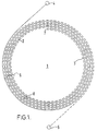
- a heating wire 2, 3 is set out therein in a spiral form and is in fact in the configuration of a closed-end bipolar loop having an ingoing part 2 and an outgoing part 3, so that in practice on the saddle fitting 1 the heating wire runs from a first terminal 4 adjacent the radially outer part of the fitting in a decreasing spiral, round an opening (not shown) at the centre of the fitting, to the radially inner part of a heating zone 6 within a groove cut appropriately therefor, in the fusion wall (not shown) of the fitting and returns in parallel increasing spiral grooves, to a second terminal adjacent the radially outer part of the fitting.
- Such an arrangement involves difficulties in laying the heating wire, particularly at the "turn-round" point 7 at the radially innermost portion thereof, but even more seriously, due at least partly to the tendency of molten plastics material from the fitting during the fusion process, and hence the included heating wire, to move primarily parallel to the fusion wall, involves a serious short-circuiting problem, in that should incoming and outgoing adjacent parts of the wire contact and short-circuit at, say, a position 8 halfway across the heating zone, the radially outer part of the heating wire will continue to heat, whilst the inner part will fail to do so.
- the fitting will be fused over the radially outer portion of the heating zone but not at the radially inner, thereby giving a false impression of secure fusion between the fitting and the pipe on which it is mounted, leading to the possibility in use of leakage and failure generally of the fitting on the pipe.
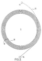
- FIG. 2 represents schematically the wiring of a saddle-type fitting similar to that represented in Figure 1, but in this case incorporating an arrangement of grooving and wiring in accordance with the present invention.
- a lead-in part 10 of a heating wire from a first terminal 11, is laid in a gently curving half-spiral groove as it is formed in the fusion wall (not shown) of the fitting from the radially outer part of the fitting to the inner part of a heating zone 12 thereof, the groove being such that the heating wire in this lead-in portion of the wire is at all points across the heating zone at a depth of approximately one and a half times the diameter of the heating wire.
- the groove and the wire laid therein are raised close to the fusion wall surface (not shown) and are then traversed outwardly in a spiral 13 around the fusion wall of the fitting such that the wire lies at or adjacent the surface of such fusion wall and therefore passes above the lead-in portion 10 of the heating wire, which is safely insulated therefrom by the wall thickness therebetween, to a second terminal 14. It is to be observed that since, as noted above, movement of molten plastics material of the fitting during fusion is predominantly parallel to the fusion wall, the disposition of the lead-in portion of the heating wire below the heating zone 12 portion of the wire, reduces very greatly any risk of short circuiting between the two portions 10 and 12.
- Any flaps or similar disturbed material at the surface of the internal wall of the fitting may be then removed by milling or similar mechanical working so as to ensure location of the spiral portion of the heating wire at or closely adjacent the surface of the inner wall of the fitting.
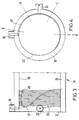
- Figures 3 to 7 of the drawings illustrate a sleeve-type weldable plastics pipe fitting.
- the fitting may, for example, be a double ended fitting arranged to connect at each end to a pipe disposed within that end of the sleeve-like fitting.
- Figure 3 shows one end 15 of such a fitting 16 in which, in accordance with the invention, a lead-in portion 17, connecting from a first external input/output terminal 18, of heating wire is laid in a half-helical groove as it is cut by a cutting tool (not shown) at a depth substantially below the surface of the infusion wall 19 of the sleeve at a depth such that the lead-in portion 17 of the heating wire is at all points over a heating zone 20 approximately at its least, twice the diameter of the heating wire below the surface of the fusion wall 19.
- the cutting tool On reaching the inner part of the heating zone of the sleeve, the cutting tool is then raised to adjacent the surface of the fusion wall 19 of the sleeve and moved in a close pitched helix 23 to the outer end 21 of the sleeve, the wire disposed therein being thereby adjacent the surface of the inner wall 19 of the sleeve, the heating wire therein connecting to a second input/output terminal 22 protruding from the outer side of the sleeve.
- the ends of the fitting can, by means of the invention, be welded in separate operations to two pipe ends. With large and heavy pipes and fittings this is of great benefit to on-site operators.
- the lead-in portion 10, 17 is said to comprise a half-spiral or a half-helix
- this lead-in configuration can vary considerably, depending upon, amongst other things, the operational requirements of the cutting tool used for its formation.
- the lead-in portion may comprise one or two spiral or helical turns.
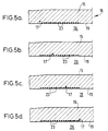
- Figures 5 (a), (b), (c) and (d), which comprise the sections on lines "A", "B", “C” and “D” of Figure 3 clearly show the lead-in portion 17 of the heating wire in its disposition buried beneath the inner wall 19 of the sleeve 16.
- the depth of the lead-in portion is, at its least, not less than approximately twice the diameter of the heating wire across the heating zone 20.
- These sections also show the helically wound portion 23 of the heating wire laying closely adjacent to the surface of the inner wall 19 of the sleeve, and indeed having a significant part of its surface exposed to the interior 26 of the sleeve.
- the sleeve fitting 16 is manufactured to an adequate tolerance to provide a narrow gap about a pipe 27 to which it is to be fused in the function of use of the fitting in connection to a pipe end.
- the terminals 18, 22 are connected across a power source which thereby heats the heating wire over the heating zone 20, and fuses together the plastics material adjacent the inner wall 19 of the fitting 16 at the heating zone 20 and part of the outer wall 28 of the pipe adjacent the heating zone.
Landscapes
- Engineering & Computer Science (AREA)
- Mechanical Engineering (AREA)
- General Engineering & Computer Science (AREA)
- Branch Pipes, Bends, And The Like (AREA)
- Lining Or Joining Of Plastics Or The Like (AREA)
- Rigid Pipes And Flexible Pipes (AREA)
- Non-Disconnectible Joints And Screw-Threaded Joints (AREA)
Applications Claiming Priority (2)
| Application Number | Priority Date | Filing Date | Title |
|---|---|---|---|
| GB9504175 | 1995-03-02 | ||
| GB9504175A GB2298466B (en) | 1995-03-02 | 1995-03-02 | Weldable pipe fittings and methods of forming the same |
Publications (3)
| Publication Number | Publication Date |
|---|---|
| EP0730118A2 true EP0730118A2 (de) | 1996-09-04 |
| EP0730118A3 EP0730118A3 (de) | 1998-02-11 |
| EP0730118B1 EP0730118B1 (de) | 2001-06-13 |
Family
ID=10770512
Family Applications (1)
| Application Number | Title | Priority Date | Filing Date |
|---|---|---|---|
| EP96301207A Expired - Lifetime EP0730118B1 (de) | 1995-03-02 | 1996-02-22 | Schweissrohrverbindung und Verfahren zu ihrer Herstellung |
Country Status (4)
| Country | Link |
|---|---|
| EP (1) | EP0730118B1 (de) |
| AT (1) | ATE202195T1 (de) |
| DE (1) | DE69613257D1 (de) |
| GB (1) | GB2298466B (de) |
Family Cites Families (5)
| Publication number | Priority date | Publication date | Assignee | Title |
|---|---|---|---|---|
| FR2519578A1 (fr) * | 1981-07-01 | 1983-07-18 | Sam Innovation Tech | Dispositif en matiere plastique pour realiser une perforation dans un element sous-jacent en matiere plastique, procede de fabrication d'un tel dispositif et sa mise en oeuvre pour realiser des derivations de canalisations |
| ATE27053T1 (de) * | 1982-05-12 | 1987-05-15 | Geberit Ag | Schweissmuffe. |
| US4915417A (en) * | 1988-08-02 | 1990-04-10 | Flo-Control, Inc. | Thermally assembled conduitry |
| EP0357551B1 (de) * | 1988-08-29 | 1991-10-09 | Geberit AG | Formstück aus Kunststoff für Rohrsysteme |
| CH687161A5 (de) * | 1994-01-10 | 1996-09-30 | Fischer Georg Rohrleitung | Elektrisch schweissbares Formteil aus Kunststoff. |
-
1995
- 1995-03-02 GB GB9504175A patent/GB2298466B/en not_active Expired - Lifetime
-
1996
- 1996-02-22 EP EP96301207A patent/EP0730118B1/de not_active Expired - Lifetime
- 1996-02-22 DE DE69613257T patent/DE69613257D1/de not_active Expired - Lifetime
- 1996-02-22 AT AT96301207T patent/ATE202195T1/de active
Also Published As
| Publication number | Publication date |
|---|---|
| EP0730118B1 (de) | 2001-06-13 |
| DE69613257D1 (de) | 2001-07-19 |
| EP0730118A3 (de) | 1998-02-11 |
| GB2298466B (en) | 1998-10-07 |
| GB2298466A (en) | 1996-09-04 |
| GB9504175D0 (en) | 1995-04-19 |
| ATE202195T1 (de) | 2001-06-15 |
Similar Documents
| Publication | Publication Date | Title |
|---|---|---|
| US4670078A (en) | Process for heat-sealing thermoplastic conduits | |
| EP1660803B1 (de) | Verfahren zur verbindung eines mehrlagigen rohrs | |
| US6131954A (en) | Weldable couple for electrofusion coupling of profile wall thermoplastic pipes without a separate coupler | |
| CA1278595C (en) | Pipe joint connecting plastic pipes and process of making such joint | |
| EP1851476B1 (de) | Verfahren zur verbindung eines mehrlagigen rohrs | |
| US4626308A (en) | Method of making welded pipe joints | |
| US20080048439A1 (en) | Method for joining multi-layered pipe | |
| US5489403A (en) | Method for welding pipe pieces made of thermoplastics | |
| EP0058175A1 (de) | Elektrische schmelzverbindung für rohre. | |
| EP0505083B1 (de) | Schweissbare Rohranschlussstücke und damit hergestellte Rohrverbindungen | |
| EP0730118B1 (de) | Schweissrohrverbindung und Verfahren zu ihrer Herstellung | |
| US6215107B1 (en) | Heating coil fitting with shrunk-on cover and process for same | |
| GB2284179A (en) | Electrofusion coupling element | |
| JPS63152792A (ja) | 管継手 | |
| CN219493354U (zh) | 工业用无干扰钢塑复合管连接结构 | |
| JP2721465B2 (ja) | 電気融着式プラスチック管継手 | |
| JP2023055438A (ja) | 電気融着継手 | |
| JPH0226398A (ja) | 溶着継手 | |
| CA2280146A1 (en) | Method of an apparatus for electrofusion coupling of profile wall thermoplastic pipes without a coupler |
Legal Events
| Date | Code | Title | Description |
|---|---|---|---|
| PUAI | Public reference made under article 153(3) epc to a published international application that has entered the european phase |
Free format text: ORIGINAL CODE: 0009012 |
|
| AK | Designated contracting states |
Kind code of ref document: A2 Designated state(s): AT BE CH DE DK ES FR IT LI NL SE |
|
| PUAL | Search report despatched |
Free format text: ORIGINAL CODE: 0009013 |
|
| AK | Designated contracting states |
Kind code of ref document: A3 Designated state(s): AT BE CH DE DK ES FR IT LI NL SE |
|
| 17P | Request for examination filed |
Effective date: 19980729 |
|
| RAP1 | Party data changed (applicant data changed or rights of an application transferred) |
Owner name: RUTLAND PLASTICS LIMITED |
|
| 17Q | First examination report despatched |
Effective date: 20000131 |
|
| GRAG | Despatch of communication of intention to grant |
Free format text: ORIGINAL CODE: EPIDOS AGRA |
|
| GRAG | Despatch of communication of intention to grant |
Free format text: ORIGINAL CODE: EPIDOS AGRA |
|
| GRAH | Despatch of communication of intention to grant a patent |
Free format text: ORIGINAL CODE: EPIDOS IGRA |
|
| GRAH | Despatch of communication of intention to grant a patent |
Free format text: ORIGINAL CODE: EPIDOS IGRA |
|
| GRAA | (expected) grant |
Free format text: ORIGINAL CODE: 0009210 |
|
| AK | Designated contracting states |
Kind code of ref document: B1 Designated state(s): AT BE CH DE DK ES FR IT LI NL SE |
|
| PG25 | Lapsed in a contracting state [announced via postgrant information from national office to epo] |
Ref country code: NL Free format text: LAPSE BECAUSE OF FAILURE TO SUBMIT A TRANSLATION OF THE DESCRIPTION OR TO PAY THE FEE WITHIN THE PRESCRIBED TIME-LIMIT Effective date: 20010613 Ref country code: LI Free format text: LAPSE BECAUSE OF FAILURE TO SUBMIT A TRANSLATION OF THE DESCRIPTION OR TO PAY THE FEE WITHIN THE PRESCRIBED TIME-LIMIT Effective date: 20010613 Ref country code: IT Free format text: LAPSE BECAUSE OF FAILURE TO SUBMIT A TRANSLATION OF THE DESCRIPTION OR TO PAY THE FEE WITHIN THE PRE;WARNING: LAPSES OF ITALIAN PATENTS WITH EFFECTIVE DATE BEFORE 2007 MAY HAVE OCCURRED AT ANY TIME BEFORE 2007. THE CORRECT EFFECTIVE DATE MAY BE DIFFERENT FROM THE ONE RECORDED.SCRIBED TIME-LIMIT Effective date: 20010613 Ref country code: FR Free format text: LAPSE BECAUSE OF FAILURE TO SUBMIT A TRANSLATION OF THE DESCRIPTION OR TO PAY THE FEE WITHIN THE PRESCRIBED TIME-LIMIT Effective date: 20010613 Ref country code: CH Free format text: LAPSE BECAUSE OF FAILURE TO SUBMIT A TRANSLATION OF THE DESCRIPTION OR TO PAY THE FEE WITHIN THE PRESCRIBED TIME-LIMIT Effective date: 20010613 Ref country code: BE Free format text: LAPSE BECAUSE OF FAILURE TO SUBMIT A TRANSLATION OF THE DESCRIPTION OR TO PAY THE FEE WITHIN THE PRESCRIBED TIME-LIMIT Effective date: 20010613 Ref country code: AT Free format text: LAPSE BECAUSE OF FAILURE TO SUBMIT A TRANSLATION OF THE DESCRIPTION OR TO PAY THE FEE WITHIN THE PRESCRIBED TIME-LIMIT Effective date: 20010613 |
|
| REF | Corresponds to: |
Ref document number: 202195 Country of ref document: AT Date of ref document: 20010615 Kind code of ref document: T |
|
| REF | Corresponds to: |
Ref document number: 69613257 Country of ref document: DE Date of ref document: 20010719 |
|
| PG25 | Lapsed in a contracting state [announced via postgrant information from national office to epo] |
Ref country code: SE Free format text: LAPSE BECAUSE OF FAILURE TO SUBMIT A TRANSLATION OF THE DESCRIPTION OR TO PAY THE FEE WITHIN THE PRESCRIBED TIME-LIMIT Effective date: 20010913 Ref country code: DK Free format text: LAPSE BECAUSE OF FAILURE TO SUBMIT A TRANSLATION OF THE DESCRIPTION OR TO PAY THE FEE WITHIN THE PRESCRIBED TIME-LIMIT Effective date: 20010913 |
|
| PG25 | Lapsed in a contracting state [announced via postgrant information from national office to epo] |
Ref country code: DE Free format text: LAPSE BECAUSE OF FAILURE TO SUBMIT A TRANSLATION OF THE DESCRIPTION OR TO PAY THE FEE WITHIN THE PRESCRIBED TIME-LIMIT Effective date: 20010914 |
|
| NLV1 | Nl: lapsed or annulled due to failure to fulfill the requirements of art. 29p and 29m of the patents act | ||
| PG25 | Lapsed in a contracting state [announced via postgrant information from national office to epo] |
Ref country code: ES Free format text: LAPSE BECAUSE OF FAILURE TO SUBMIT A TRANSLATION OF THE DESCRIPTION OR TO PAY THE FEE WITHIN THE PRESCRIBED TIME-LIMIT Effective date: 20011220 |
|
| EN | Fr: translation not filed | ||
| REG | Reference to a national code |
Ref country code: CH Ref legal event code: PL |
|
| PLBE | No opposition filed within time limit |
Free format text: ORIGINAL CODE: 0009261 |
|
| STAA | Information on the status of an ep patent application or granted ep patent |
Free format text: STATUS: NO OPPOSITION FILED WITHIN TIME LIMIT |
|
| 26N | No opposition filed |