EP0730149A2 - Linearisierte potentiometrische Elektrode - Google Patents
Linearisierte potentiometrische Elektrode Download PDFInfo
- Publication number
- EP0730149A2 EP0730149A2 EP96301139A EP96301139A EP0730149A2 EP 0730149 A2 EP0730149 A2 EP 0730149A2 EP 96301139 A EP96301139 A EP 96301139A EP 96301139 A EP96301139 A EP 96301139A EP 0730149 A2 EP0730149 A2 EP 0730149A2
- Authority
- EP
- European Patent Office
- Prior art keywords
- temperature
- resistance
- ion
- log
- membrane
- Prior art date
- Legal status (The legal status is an assumption and is not a legal conclusion. Google has not performed a legal analysis and makes no representation as to the accuracy of the status listed.)
- Withdrawn
Links
Images

Classifications
-
- G—PHYSICS
- G01—MEASURING; TESTING
- G01N—INVESTIGATING OR ANALYSING MATERIALS BY DETERMINING THEIR CHEMICAL OR PHYSICAL PROPERTIES
- G01N27/00—Investigating or analysing materials by the use of electric, electrochemical, or magnetic means
- G01N27/26—Investigating or analysing materials by the use of electric, electrochemical, or magnetic means by investigating electrochemical variables; by using electrolysis or electrophoresis
- G01N27/416—Systems
- G01N27/4163—Systems checking the operation of, or calibrating, the measuring apparatus
- G01N27/4165—Systems checking the operation of, or calibrating, the measuring apparatus for pH meters
Definitions
- the invention relates to electrochemical sensors and, more particularly, to temperature-corrected electrochemical sensors characterized by an improved linearized response.
- Electrochemical sensors are used to detect the presence of ions in solution.
- a common form of such sensor is the well-known pH electrode which measures the concentration of H + ions in solution.
- Such a sensor is typically formed from a body having a membrane selectively permeable to H + ions formed or mounted on a surface thereof for immersion in, or at least contact with, a solution (or semi-solid such as meat, cheese, soil, and the like) to be measured on an exterior face thereof.
- a filling solution of controlled composition within the body contacts the interior of the membrane and provides a standard potential for an electrode such as a wire which is immersed in the solution.
- Changes in the pH of the test material (solution, etc.) to which the membrane is exposed change the potential of the electrode with respect to a reference electrode that is also in contact with the test material.
- the change in potential between the sensing and reference electrodes provides a direct indication of the pH of the test material.
- Electrodes of this type when used with a membrane that is specific to the ion to be measured, are also commonly used to measure other ions such as Na + , K + , Ca 2+ , F and other mono-valent and divalent cations and anions; and are referred to generally as "ion-selective" electrodes. When available for the particular ion to be measured, such electrodes are very popular, since they usually provide a relatively fast and simple means of measurement with reasonable accuracy.
- E E 0 + (RT/nF)
- R the gas constant
- T the absolute temperature
- n the charge on the ion(s)
- F the Faraday constant
- a the activity of the ion(s). Accordingly, it is essential that the readings of such electrodes be corrected for temperature.
- Temperature correction is sometimes accomplished by separately measuring the temperature of the test material (e.g., solution) in which the electrode is immersed and thereafter applying a calculated correction factor to readings taken with the electrode.
- this technique is subject to variable error arising from spatial separation between the temperature measuring element and the sensing membrane.
- the invention described in the '544 patent makes use of the fact that the logarithm of the resistance of pH sensitive membranes varies inversely with the temperature of the material (e.g., solution) being measured. This fact is used to advantage by applying an externally-generated alternating voltage across the membrane in parallel with the DC voltage generated by the ion concentration differences across the membrane that arise from the material under test. The alternating voltage is used to measure the instantaneous resistance of the membrane and thus provide a correction factor for the measurement. This technique is referred to hereinafter as "the log R" technique.
- the present invention is directed to an improved linearized, temperature corrected electrochemical sensor and measurement system.
- the present invention provides an improved linearized, temperature corrected electrochemical sensor that is characterized by a temperature correction factor of narrow dispersion despite the use of membranes of different types and materials and an improved log R temperature measurement system including an improved log R algorithm and noise reduction techniques.
- the present invention provides a temperature corrected electrode of the log R type that provides a relatively linear temperature correction factor of narrow dispersion over a broad range of temperatures.
- the temperature correction linearity of this log R type electrode may be further enhanced through the application of a more advanced temperature correction algorithm. This same advanced algorithm provides advantages in improved linearity in non-log R type electrodes.
- the target R-T calibration curve may advantageously be formed as the average of the R-T curves of a pair of spherical membranes of the type commonly used in pH and other ion-selective membranes.
- the membrane pair are specifically chosen from among possible candidates for the closeness of the match of their R-T curves and their linearity over a wide operating temperature range, e.g., over a range on the order of from near zero degrees Celsius (0°C) to near one hundred degrees Celsius (100°C).
- the membranes to be used in the electrodes are fitted to this curve. This is accomplished, for example, by varying the thickness of the material to be used in the electrode membrane by small amounts as necessary to increase or decrease the resistance values so that they fall on the calibration curve as nearly as possible over the temperature range.
- the shape of the membrane is desirably also carefully controlled, since this can have a significant effect on the R-T characteristic of the membrane. It has been discovered that superior performance is obtained with spherical (5.5 - 9 mm diameter) bulbs and flat membranes of relatively uniform size. Consistency in forming and shaping the membrane material also enhance the ability to match the membrane to the target calibration R-T curve.
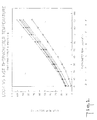
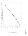
- Figures 1 and 2 are graphs of the temperature of a test solution as calculated by a log R meter in the absence of the improvement of the present invention (vertical axis) as a function of the NIST thermometer measured temperature (horizontal axis) for a variety of membranes which may be used with the meter for varying applications.
- Figure 1 is before temperature calibration of the algorithm
- Figure 2 is after temperature calibration of the algorithm.
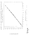
- Figures 3 and 4 are graphs of the temperature of a test solution as calculated by a log R meter as enhanced by the present invention (vertical axis) as a function of the NIST thermometer measured temperature (horizontal axis) for the same membranes as in Figures 1 and 2 but showing the remarkably reduced temperature dispersion attendant on the present invention.
- Figure 3 is before temperature calibration of the algorithm
- Figure 4 is after temperature calibration of the algorithm.
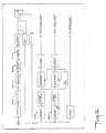
- Figure 5 is a block diagram of the new and improved log R system as discussed in the examples.
- Fig. 2 the temperature as calculated and indicated by a meter of the log R type (see U.S. Patent No. 4,321,544 supra) for ion-selective electrodes using six different membranes, A, B, C, D, E, and F respectively, is shown as compared to the temperature measured by a NIST certified thermometer.
- the temperature calculated by the log R meter for a given solution may vary by as much as about 15°C from the actual solution temperature at the electrodes and the potential correction computed from the Nernst equation with these data will vary accordingly. This has heretofore constrained the utilization of such a meter with a variety of electrodes, over a wide temperature range.
- Figure 4 shows the remarkable reduction, and near elimination, of the temperature dispersion for the same electrodes as in Fig. 2, as a consequence of implementation of the present invention.
- an improved log R meter adjusted to the target calibration curve, and further calibrated to an individual electrode, will provide a response that is essentially independent of the particular electrode type and manufacturing variations.
- the present invention thus greatly expands the usefulness of the log R type meters.
- the optimum electrode resistance for Log R performance between about 0° and 100°C is from 50 to 300 Megohms at 25°C. These resistance limits are based on electrical limits of measurement based on the electrodes cable capacitance and reference electrode impedance. At higher or lower resistances some reduction in accuracy occurs at the ends of the temperature range. For instance at higher resistance the accuracy begins to degrade when the temperature approaches 0°C and with lower resistances the accuracy begins to degrade when the temperature approaches 100°C. Testing has shown that acceptable accuracy across the full temperature range can still be achieved with electrode resistances that are over three times higher and two-thirds lower than the optimal.
- Eleven electrode models (3-4 of each) were tested at 15 temperatures, ranging from 0 - 90°C.
- the testing sequence was conducted with both increasing and decreasing temperature steps to test for hysteresis and the tests were repeated after 2 and 4 week periods to test for and evaluate drift.
- testing was conducted in various buffers (4, 7, and 10 pH) to determine if there were any pH interferences on the membranes temperature response.
- the test instrumentation consisted of a 6 channel measuring circuit using an AC signal superimposed on the DC potential generated by the electrode. The circuit was designed to reject the out of phase components of the AC signal measured to eliminate inductive or capacitive effects of the system (In a micro based instrument this could also be accomplished by measuring the capacitance of the electrode/system and eliminating it in software).
- the 1000 in the 1000 over T is a scaling factor and is not a fundamental part of the mathematical relationship.
- the default values were an average of the typical calibration values measured for the electrode models used in the testing.
- Previously, in U.S. Pat. No. 4,321,544, it had been shown that the temperature on an electrodes membrane was inversely proportional to the logarithm of the membranes resistance (this equation is shown below): (Equation 2) 1/T A * In(R) + B Where:
- Equation 1 has the best accuracy, but equation 3 requires only two (2) calibration points for its maximum accuracy versus the three (3) calibration points needed with equation 1 for its maximum accuracy.
- the remaining tables (infra) and Figures 1 - 4 illustrate the results of each of the three models described above.
- the present inventors were able to determine from the test data that the membrane resistance was unaffected by solution pH and that there was no hysteresis in the membrane temperature response. The testing also showed that the electrodes Log R temperature response drift was less than 0.1°C per week. This drift was primarily in the "A" coefficient of equation 1, and primarily effected the low temperature (below 40°C) response.
- FIG. 5 is a block diagram of the Improved Log R System, which should be referred to for the discussion that follows:
- a sinusoidal voltage of stable amplitude and frequency is used to measure the electrode resistance.
- 5Hz was selected to minimize interference from 50Hz and 60Hz power. The minimization occurs because each half cycle of 5Hz contains an integral number of cycles of 50Hz or 60Hz.
- the frequency is produced with two counters directly from the crystal oscillator of the microprocessor.
- a switched reference gives a 5Hz square wave of known amplitude. This is fed to a switched capacitor bandpass filter whose output is a stepped approximation of a sinusoid.
- the bandpass filter output goes to an on/off switch that allows the computer system to inject Log R drive voltage or not depending on the instrument operating mode.
- the on/off switch feeds a lowpass filter that removes the steps produced by the bandpass filter and outputs a stable sinusoidal drive signal.
- the sinusoidal signal drive signal is fed into the electrode by means of a resistor, R and capacitor C.
- the capacitor prevents the low impedance and DC voltage of the lowpass filter from affecting the DC output of the electrode.
- the function of the resistor is described below.
- the impedance of an electrode has two predominant terms:
- the total voltage on the electrode is measured at the output of a high input impedance buffer.
- the voltage consists of two signals:
- Measuring the voltage across R gives the total current into the electrode. The part of the total current that is in phase with the electrode voltage is used to determine the electrode resistance. The part of the total current that is out of phase is ignored.
- the voltage and current signals for measuring the electrode resistance are processed through two identical filter channels.
- a highly sensitive circuit is used to determine the zero crossing of the voltage channel. Its output is used to synchronously rectify the voltage and current channels.
- the output of the voltage channel rectifier is a full wave rectified sinusoid, which has a DC average value.
- the output of the current channel rectifier has two parts:
- Three lowpass filters are used to supply inputs to the Analog to Digital Converter. Two filters get rid of the AC components of the Log R voltage and current synchronous rectifiers described above. A third extracts the DC electrode voltage from the electrode input buffer by removing the 5Hz signal.
- Test data for the following 9 models (1 each) of electrodes were obtained and evaluated at 15 temperatures, ranging from 0° to 90°C. These electrodes were retested 7 weeks later for Model Nos. 8235, 9207, 8202, 8272, & 8256, and 5 weeks later for Model Nos. 9256, 9202, 9203, & 9206. The retest results were used to perform a 1, 2 and 3 point calibration. Below are tables (6-15) of the original data using the 1, 2 and 3 point calibrations obtained from the retest. As can be seen there was very little drift over this 5 - 7 week period. The drift was approximately 0.1°C per week.
- Test data for the following nine models (one each) of electrodes were obtained and evaluated at 15 temperatures, ranging from 0 - 90°C. Using a 2 point calibrations at various temperatures for the A & C values, the following results (Tables 16-18) were obtained in comparing the calculated temperature to the thermistor measured values.
Landscapes
- Chemical & Material Sciences (AREA)
- Life Sciences & Earth Sciences (AREA)
- Health & Medical Sciences (AREA)
- Physics & Mathematics (AREA)
- Chemical Kinetics & Catalysis (AREA)
- Electrochemistry (AREA)
- Molecular Biology (AREA)
- Analytical Chemistry (AREA)
- Biochemistry (AREA)
- General Health & Medical Sciences (AREA)
- General Physics & Mathematics (AREA)
- Immunology (AREA)
- Pathology (AREA)
- Investigating Or Analyzing Materials By The Use Of Electric Means (AREA)
Applications Claiming Priority (2)
| Application Number | Priority Date | Filing Date | Title |
|---|---|---|---|
| US39759995A | 1995-03-02 | 1995-03-02 | |
| US397599 | 1995-03-02 |
Publications (2)
| Publication Number | Publication Date |
|---|---|
| EP0730149A2 true EP0730149A2 (de) | 1996-09-04 |
| EP0730149A3 EP0730149A3 (de) | 1997-05-21 |
Family
ID=23571857
Family Applications (1)
| Application Number | Title | Priority Date | Filing Date |
|---|---|---|---|
| EP96301139A Withdrawn EP0730149A3 (de) | 1995-03-02 | 1996-02-21 | Linearisierte potentiometrische Elektrode |
Country Status (2)
| Country | Link |
|---|---|
| US (1) | US6168707B1 (de) |
| EP (1) | EP0730149A3 (de) |
Cited By (1)
| Publication number | Priority date | Publication date | Assignee | Title |
|---|---|---|---|---|
| CN106841363A (zh) * | 2017-02-15 | 2017-06-13 | 四川大学 | 基于电位测定的电子集成多电极检测系统 |
Families Citing this family (5)
| Publication number | Priority date | Publication date | Assignee | Title |
|---|---|---|---|---|
| WO2004046707A1 (en) * | 2002-11-18 | 2004-06-03 | Advanced Sensor Technologies | Microscopic multi-site sensor array with integrated control and analysis circuitry |
| US20040249600A1 (en) * | 2003-06-03 | 2004-12-09 | Tiller William A. | Apparatus and methods of measuring a thermodynamic potential of a limited physical space characterized by a series of symmetry states |
| JP2007324659A (ja) * | 2006-05-30 | 2007-12-13 | Sony Corp | チャージドメインフィルタ回路 |
| CN111383904A (zh) | 2015-11-17 | 2020-07-07 | Atonarp株式会社 | 分析装置及其控制方法 |
| CN110186987B (zh) * | 2019-06-27 | 2022-03-08 | 上海三信仪表厂 | 一种通用的溶液ph值25度折算方法 |
Family Cites Families (6)
| Publication number | Priority date | Publication date | Assignee | Title |
|---|---|---|---|---|
| US3662256A (en) | 1970-04-27 | 1972-05-09 | Leeds & Northrup Co | Hydroxyl ion measuring system |
| US4222006A (en) | 1978-12-18 | 1980-09-09 | Catalyst Research Corporation | Thermal composition circuit for electrochemical detectors |
| US4321544A (en) * | 1980-02-19 | 1982-03-23 | Riseman John H | Method and improved apparatus for obtaining temperature-corrected readings of ion levels and readings of solution temperature |
| US4495050A (en) | 1980-11-28 | 1985-01-22 | Ross Jr James W | Temperature insensitive potentiometric electrode system |
| US4851104A (en) * | 1987-02-27 | 1989-07-25 | General Signal Corporation | Instrument for potentiometric electrochemical measurements |
| DE3840961A1 (de) * | 1988-12-05 | 1990-06-07 | Hellige Gmbh | Ionensensitive elektrode und verfahren zur temperaturgangkompensation bei solchen elektroden |
-
1996
- 1996-02-21 EP EP96301139A patent/EP0730149A3/de not_active Withdrawn
-
1998
- 1998-09-24 US US09/160,125 patent/US6168707B1/en not_active Expired - Lifetime
Cited By (2)
| Publication number | Priority date | Publication date | Assignee | Title |
|---|---|---|---|---|
| CN106841363A (zh) * | 2017-02-15 | 2017-06-13 | 四川大学 | 基于电位测定的电子集成多电极检测系统 |
| CN106841363B (zh) * | 2017-02-15 | 2019-05-14 | 四川大学 | 基于电位测定的电子集成多电极检测系统 |
Also Published As
| Publication number | Publication date |
|---|---|
| US6168707B1 (en) | 2001-01-02 |
| EP0730149A3 (de) | 1997-05-21 |
Similar Documents
| Publication | Publication Date | Title |
|---|---|---|
| US7550979B2 (en) | System and method for measuring conductivity of fluid | |
| EP2405263B1 (de) | Analyse eines dielektrischen Mediums | |
| US7772854B2 (en) | High-conductivity contacting-type conductivity measurement | |
| US4259633A (en) | Method and apparatus for measuring the moisture content of wood | |
| US3331021A (en) | A. c. corrosion-rate meter and method | |
| US9488611B2 (en) | Low-conductivity contacting-type conductivity measurement | |
| US5872454A (en) | Calibration procedure that improves accuracy of electrolytic conductivity measurement systems | |
| US20030006148A1 (en) | Method and apparatus for measuring accumulated and instant rate of material loss or material gain | |
| US20160161446A1 (en) | Low slope ph electrode with charge transfer component | |
| US6168707B1 (en) | Ion measurement apparatus and methods for improving the accuracy thereof | |
| US4321544A (en) | Method and improved apparatus for obtaining temperature-corrected readings of ion levels and readings of solution temperature | |
| Bera et al. | A modified Schering bridge for measurement of the dielectric parameters of a material and the capacitance of a capacitive transducer | |
| US20010052768A1 (en) | Proximity sensor method and apparatus that is insensitive to temperature, noise and length of wire | |
| US3593118A (en) | Apparatus for measuring the electrical conductivity of liquids having dielectric-faced electrodes | |
| US2902639A (en) | Apparatus for the measurement of fluid conductivity | |
| JPH09236567A (ja) | 線形ポテンショメータ電極 | |
| SU1474452A1 (ru) | Способ контрол поверхности электропровод щих изделий и устройство дл его осуществлени | |
| CA1262372A (en) | Method for the measurement of capacitances, in particular of low capacitances, wherein two references are used | |
| Breuel et al. | Experiences with novel secondary conductivity sensors within the German calibration service (DKD) | |
| Brkic et al. | Signal processing interface for displacement measurement | |
| RU2122225C1 (ru) | Способ градуировки аппаратуры индукционного каротажа | |
| Britz | Evaluation of electrochemical cell impedance parameters | |
| SU391459A1 (ru) | Электронный влагомер | |
| FI110640B (fi) | Menetelmä hygroskooppisen materiaalin pintakerroksen syvyyssuuntaisen kosteusjakauman mittaamiseksi | |
| SU1694698A1 (ru) | Устройство дл измерени максимальной скорости коррозии магистральных трубопроводов |
Legal Events
| Date | Code | Title | Description |
|---|---|---|---|
| PUAI | Public reference made under article 153(3) epc to a published international application that has entered the european phase |
Free format text: ORIGINAL CODE: 0009012 |
|
| AK | Designated contracting states |
Kind code of ref document: A2 Designated state(s): CH DE FR GB LI |
|
| AX | Request for extension of the european patent |
Free format text: LV |
|
| RAX | Requested extension states of the european patent have changed |
Free format text: LV |
|
| PUAL | Search report despatched |
Free format text: ORIGINAL CODE: 0009013 |
|
| AK | Designated contracting states |
Kind code of ref document: A3 Designated state(s): CH DE FR GB LI |
|
| AX | Request for extension of the european patent |
Free format text: LV |
|
| 17P | Request for examination filed |
Effective date: 19970820 |
|
| 17Q | First examination report despatched |
Effective date: 20020304 |
|
| STAA | Information on the status of an ep patent application or granted ep patent |
Free format text: STATUS: THE APPLICATION IS DEEMED TO BE WITHDRAWN |
|
| 18D | Application deemed to be withdrawn |
Effective date: 20020716 |