EP0730236A1 - Procédé et circuit de saisie et transmission de données vidéos dans un ordinateur personnel - Google Patents
Procédé et circuit de saisie et transmission de données vidéos dans un ordinateur personnel Download PDFInfo
- Publication number
- EP0730236A1 EP0730236A1 EP96103100A EP96103100A EP0730236A1 EP 0730236 A1 EP0730236 A1 EP 0730236A1 EP 96103100 A EP96103100 A EP 96103100A EP 96103100 A EP96103100 A EP 96103100A EP 0730236 A1 EP0730236 A1 EP 0730236A1
- Authority
- EP
- European Patent Office
- Prior art keywords
- scsi
- data
- controller
- pci
- circuit
- Prior art date
- Legal status (The legal status is an assumption and is not a legal conclusion. Google has not performed a legal analysis and makes no representation as to the accuracy of the status listed.)
- Withdrawn
Links
Images




Classifications
-
- H—ELECTRICITY
- H04—ELECTRIC COMMUNICATION TECHNIQUE
- H04N—PICTORIAL COMMUNICATION, e.g. TELEVISION
- H04N1/00—Scanning, transmission or reproduction of documents or the like, e.g. facsimile transmission; Details thereof
- H04N1/00127—Connection or combination of a still picture apparatus with another apparatus, e.g. for storage, processing or transmission of still picture signals or of information associated with a still picture
- H04N1/00204—Connection or combination of a still picture apparatus with another apparatus, e.g. for storage, processing or transmission of still picture signals or of information associated with a still picture with a digital computer or a digital computer system, e.g. an internet server
- H04N1/00236—Connection or combination of a still picture apparatus with another apparatus, e.g. for storage, processing or transmission of still picture signals or of information associated with a still picture with a digital computer or a digital computer system, e.g. an internet server using an image reading or reproducing device, e.g. a facsimile reader or printer, as a local input to or local output from a computer
- H04N1/00241—Connection or combination of a still picture apparatus with another apparatus, e.g. for storage, processing or transmission of still picture signals or of information associated with a still picture with a digital computer or a digital computer system, e.g. an internet server using an image reading or reproducing device, e.g. a facsimile reader or printer, as a local input to or local output from a computer using an image reading device as a local input to a computer
-
- G—PHYSICS
- G06—COMPUTING OR CALCULATING; COUNTING
- G06F—ELECTRIC DIGITAL DATA PROCESSING
- G06F13/00—Interconnection of, or transfer of information or other signals between, memories, input/output devices or central processing units
- G06F13/38—Information transfer, e.g. on bus
- G06F13/382—Information transfer, e.g. on bus using universal interface adapter
- G06F13/385—Information transfer, e.g. on bus using universal interface adapter for adaptation of a particular data processing system to different peripheral devices
-
- H—ELECTRICITY
- H04—ELECTRIC COMMUNICATION TECHNIQUE
- H04N—PICTORIAL COMMUNICATION, e.g. TELEVISION
- H04N1/00—Scanning, transmission or reproduction of documents or the like, e.g. facsimile transmission; Details thereof
- H04N1/00127—Connection or combination of a still picture apparatus with another apparatus, e.g. for storage, processing or transmission of still picture signals or of information associated with a still picture
- H04N1/00204—Connection or combination of a still picture apparatus with another apparatus, e.g. for storage, processing or transmission of still picture signals or of information associated with a still picture with a digital computer or a digital computer system, e.g. an internet server
- H04N1/00236—Connection or combination of a still picture apparatus with another apparatus, e.g. for storage, processing or transmission of still picture signals or of information associated with a still picture with a digital computer or a digital computer system, e.g. an internet server using an image reading or reproducing device, e.g. a facsimile reader or printer, as a local input to or local output from a computer
-
- H—ELECTRICITY
- H04—ELECTRIC COMMUNICATION TECHNIQUE
- H04N—PICTORIAL COMMUNICATION, e.g. TELEVISION
- H04N1/00—Scanning, transmission or reproduction of documents or the like, e.g. facsimile transmission; Details thereof
- H04N1/32—Circuits or arrangements for control or supervision between transmitter and receiver or between image input and image output device, e.g. between a still-image camera and its memory or between a still-image camera and a printer device
- H04N1/32358—Circuits or arrangements for control or supervision between transmitter and receiver or between image input and image output device, e.g. between a still-image camera and its memory or between a still-image camera and a printer device using picture signal storage, e.g. at transmitter
-
- H—ELECTRICITY
- H04—ELECTRIC COMMUNICATION TECHNIQUE
- H04N—PICTORIAL COMMUNICATION, e.g. TELEVISION
- H04N1/00—Scanning, transmission or reproduction of documents or the like, e.g. facsimile transmission; Details thereof
- H04N1/00127—Connection or combination of a still picture apparatus with another apparatus, e.g. for storage, processing or transmission of still picture signals or of information associated with a still picture
- H04N1/00204—Connection or combination of a still picture apparatus with another apparatus, e.g. for storage, processing or transmission of still picture signals or of information associated with a still picture with a digital computer or a digital computer system, e.g. an internet server
-
- H—ELECTRICITY
- H04—ELECTRIC COMMUNICATION TECHNIQUE
- H04N—PICTORIAL COMMUNICATION, e.g. TELEVISION
- H04N2201/00—Indexing scheme relating to scanning, transmission or reproduction of documents or the like, and to details thereof
- H04N2201/0008—Connection or combination of a still picture apparatus with another apparatus
- H04N2201/0034—Details of the connection, e.g. connector, interface
-
- H—ELECTRICITY
- H04—ELECTRIC COMMUNICATION TECHNIQUE
- H04N—PICTORIAL COMMUNICATION, e.g. TELEVISION
- H04N2201/00—Indexing scheme relating to scanning, transmission or reproduction of documents or the like, and to details thereof
- H04N2201/0077—Types of the still picture apparatus
- H04N2201/0084—Digital still camera
-
- H—ELECTRICITY
- H04—ELECTRIC COMMUNICATION TECHNIQUE
- H04N—PICTORIAL COMMUNICATION, e.g. TELEVISION
- H04N5/00—Details of television systems
- H04N5/14—Picture signal circuitry for video frequency region
-
- H—ELECTRICITY
- H04—ELECTRIC COMMUNICATION TECHNIQUE
- H04N—PICTORIAL COMMUNICATION, e.g. TELEVISION
- H04N5/00—Details of television systems
- H04N5/44—Receiver circuitry for the reception of television signals according to analogue transmission standards
- H04N5/4448—Receiver circuitry for the reception of television signals according to analogue transmission standards for frame-grabbing
Definitions
- the present invention relates to a method and a circuit for acquiring and forwarding video image data in a PC with a PCI bus.
- the data is recorded with the aid of a PCI frame grabber circuit and is passed on to the main memory of the PC and / or via a graphics circuit to a monitor essentially in real time via the PCI bus.
- the data can also be routed to another memory or buffer and processed if necessary.
- a corresponding PCI frame grabber circuit has a video input, an A / D converter with an associated A / D controller for converting the incoming analog video signals into digital signals, and also has a PCI bus interface and a module , which converts or formats the digitized video data so that it can be transferred to or retrieved from the PCI bus.
- Examples of sources of video image data are area scan cameras, line scan cameras, X-ray image recorders, ultrasound sensors, laser scanners and others.
- a frame rate of at least 25 images per second is generally required, which corresponds to a data transfer of 11.06 Mbytes per second. The method and the corresponding device must therefore be able to handle such data transfer rates without complications. If a PC is to be used to display video images in real time, only PCs with a so-called PCI bus system, which has a correspondingly high maximum data transfer rate of up to 132 Mbytes per second, are suitable for this.
- a transfer of the data in real time or essentially in real time means that no longer image sequences of many seconds or minutes in duration are temporarily stored or recorded on a recording medium, but that the delay between the recording of the image data and its forwarding to a graphics circuit, the main memory or also from the graphics card to the monitor is in the range of fractions of a second.
- the amount of buffered data thus comprises less than one frame or only a few frames, which, at a frame rate of 25 frames per second, gives the human eye the impression that the video image at any time essentially corresponds to the image that is currently in use is recorded by the camera since delays of 1/10 sec or less caused by the intermediate storage are practically not perceived.
- the corresponding frame grabber circuits therefore generally have a special module developed for this video transmission, which serves as an interface module between the digitized video data on the one hand and the PCI bus on the other.
- These modules which may also have peripheral modules for controlling and monitoring the data flow, are relatively complex and expensive to manufacture, especially since the requirement at the time is still relatively low and the quantities are correspondingly low.
- the present invention has for its object to provide a method and a circuit for capturing and forwarding video image data in a PC, which are simple and inexpensive to implement.
- this object is achieved in that the 8-bit wide digital image data stream is brought to double the 16-bit width in or before the frame grabber circuit, that a standard SCSI for the recording and transmission of the 16-bit wide data stream to the PCI bus Controller is used and that only the synchronous receive clock is used when the data is recorded by the SCSI controller.
- the object on which the invention is based is achieved in that the module for formatting the digitized data into PCI-compatible data is a standard SCSI controller which has an input interface with at least 16 bit width and a synchronous reception clock.
- SCSI controllers with a PCI interface are standard components that can be found in practically all PCs with a PCI bus. They serve to the different assemblies of the PC, such as. B. its hard drive, floppy disk drives, CD-ROMs, etc. via the PCI bus with the central processor unit (CPU).
- CPU central processor unit
- the SCSI controller itself controls the data stream, ie it accesses one of the connected modules in a specific manner and according to predetermined priorities, time windows etc. and controls the data stream from the latter to the PCI bus or . vice versa.
- such a standard SCSI controller can also be used for a PCI frame grabber circuit if the digitized one is used Image data stream doubled to 16 bit width and only uses the synchronous receive clock, whereby of course a SCSI controller must be used, which has a SCSI input at least 16 bit wide and a corresponding synchronous receive clock.
- the SCSI controller has an expansion interface, which is usually used for EPROMs (for booting the PC), but which, according to the preferred embodiment of the present invention, for controlling the peripheral components such as A / D converters , A / D controller and input / output module is used.
- a SCSI controller of the type NCR 53C825 has proven to be particularly suitable for the purposes of the present invention. This has all the preferred features mentioned above.
- all control lines of the SCSI controller with the exception of a few control connections such as / SREQ, / SIO and / SACK are set to a constant potential.
- this module this is the circuit equivalent of not having to implement the SCSI protocol required for normal SCSI controller applications.
- no further control connections of the SCSI controller are required in principle for the circuit according to the invention, even if it does not have to be ruled out in principle to use further control connections to control additional components on the frame grabber card.
- control lines are expediently preferably at a constant potential placed on the supply voltage V cc , easiest with the help of a so-called pull-up resistor, the supply voltage can in principle have any value, but in practice only supply voltages of 5 V or 3.2 V are of practical importance.
- an input / output module is provided, which is also controlled by the expansion interface.
- the special feature of the present invention is the use of a standard component, which is provided per se for other purposes, which is produced in large numbers and is correspondingly inexpensive and which - in the preferred embodiment of the invention - is used for a different purpose, e.g. B. the entire control is overridden, only the synchronous receive clock is used and the digital data lines from the video camera are the only data lines connected to the SCSI interface, whereas a number of different modules are conventionally connected to the SCSI interface.
- the width of the digital data stream is doubled from 8 to 16 bits using a module that fades out every second byte on the 8-bit digital video input line into a parallel branch, the SCSI interface clocking on the input side with half the frequency of the 8-bit wide video data line , so that two bytes in succession on the 8-bit wide data line are recorded simultaneously in parallel on the SCSI interface of the SCSI controller.
- the video image data which are usually initially supplied in analog form by a video camera, must be digitized beforehand. It goes without saying that such digitization of analog data from the camera does not have to take place if the camera is already equipped with an appropriate module, so that digitized image data is already present at its output.
- a video camera 2 is indicated schematically on the left and a monitor 50 on the right, on which the images recorded by the video camera are to be displayed in real time if possible.
- the intermediate link between the camera and monitor is a PC with PCI bus 9.
- the essential elements that the PC must have in any case are shown in the field indicated by a frame 100.
- the PC has a CPU (central processor unit) 40, a working memory (RAM) 30 and a graphics card 20, which contains a digital / analog converter.
- the video camera 2 is connected to the input of the frame grabber circuit 10 on which, on the one hand, an analog / digital conversion of the data takes place and which also formats or arranges the digital data in such a way that it is either connected to the working memory of the PCI bus 9 CPU 40 or be placed on the monitor 50 via the graphics card 20.
- an Intel 486 DX / 4 processor was used for the CPU, which is clocked at 100 MHz.
- a Miro Crystal 20 SD card with the S3 Vision 864 graphics chip was used as the graphics card.
- a Miro Crystal 20 SV card with the S3 Vision 964 graphics chip was used.
- FIG. 1 an enlarged detail from FIG. 1 is shown, that of the PC only shows the PCI bus 9 and, on the other hand, the video camera 2 directly connected to the frame grabber card 10.
- the external devices 17 additionally shown under the camera 2 are only options and do not necessarily have to be present.
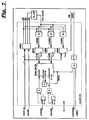
- the core of the PCI frame grabber circuit consists of a SCSI controller 1 of the NCR 53C825 type, which represents the actual interface between the video image data and the PCI bus 9.
- the analog image data originating from the camera 2 are first converted into a digital data stream in an A / D converter 4, 8 bits (1 byte) being assigned to each image pixel, which represent the brightness of the pixel in question in 256 steps.
- the PCI interface 12 of the SCSI controller 1 is connected to the PCI bus 9.
- the SCSI controller 1 also has an expansion interface 13, which is designated in FIG. 2 by the memory bus, and which is used to control the A / D converter 4, the corresponding controller 14 and other components.
- the frame grabber card is designated with a total of 10.
- the camera 2 is connected to a video input 3 of the frame grabber card 10, which leads directly into an A / D converter 4. From there, the digitized data reaches an FIFO buffer memory 5 of 1 Kbyte depth via an 8 bit wide data line 6.
- This FIFO memory is controlled via the control connection / SACK of the SCSI controller. Every second byte from line 6 is then faded out via a flip-flop 7, so that the data arrive in 16 bit width via two 8 bit wide data lines 6a and 6b at the SCSI interface 11 of the SCSI controller 1.
- the reception clock of the SCSI interface of the SCSI controller therefore only needs to be half the clock of the data line which leads from the A / D converter at the input of the circuit to the SCSI controller.
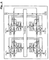
- FIG. 3 shows the timing of the image data blocks between the A / D converter 4 and the SCSI interface 11.
- the SCSI interface 11 in turn contains a further FIFO buffer memory, which, however, is only a small depth of a few bytes. Only the synchronous clock of the SCSI interface is used to read out the video data from the data lines 6a and 6b.
- the data path within the SCSI controller here of the type NCR 53C825, depends on whether it is sent or received synchronously or asynchronously. For the purposes of the present invention, only the so-called "synchronous SCSI Receive" is used, since only data is received from the SCSI bus and written to the desired destination via the PCI bus.
- the A-D controller 14 generates signals from the video, e.g. B. the synchronization pulses (H and V sync) and thus controls the A / D converter 4. These signal lines are also required by the programmable control logic 15 to generate from these signals the control information with which the SCSI controller 1 requests the bus independently and transfers the image data from the SCSI bus to the PCI bus.
- External devices can both be controlled via an input / output module 16 (e.g. a synchronized flash), and external devices can also control the PCI frame grabber, that is to say, for example, image acquisition with the aid of an external signal from an external device 17 .
- the control logic 15 of the PCI frame grabber 10 is programmed into a chip (here the Mach 210 from AMD).
- the associated Figures 5 and 6 are taken from the data book of the manufacturer "MACH Family Data Book", AMD 1992.
- the A / D controller 14 is mainly used to generate the synchronization pulses from the video signal.
- the synchronization signals are simultaneously separated and connected to the video input of the A / D controller 14 via a SYNC detector integrated in the A / D converter.
- the vertical sync signal is separated directly from the video sync pulses.
- the horizontal sync signal HSYNC is still being generated and is dependent on the set pixel clock, which is generated with the aid of the synchronous signals and an external clock, depending on the desired number of pixels per image line (maximum 4096).
- the entire system was implemented in one exemplary embodiment with a PC which had an Intel 486 / DX4 processor clocked at 100 MHz and which ran under the OS / 2 operating system.
- the frame grabber card according to the invention has also been successfully tested in other hardware environments.
Landscapes
- Engineering & Computer Science (AREA)
- General Engineering & Computer Science (AREA)
- Multimedia (AREA)
- Signal Processing (AREA)
- Computing Systems (AREA)
- Theoretical Computer Science (AREA)
- Physics & Mathematics (AREA)
- General Physics & Mathematics (AREA)
- Television Signal Processing For Recording (AREA)
- Compression Or Coding Systems Of Tv Signals (AREA)
- Image Processing (AREA)
Applications Claiming Priority (2)
| Application Number | Priority Date | Filing Date | Title |
|---|---|---|---|
| DE19507447 | 1995-03-03 | ||
| DE1995107447 DE19507447A1 (de) | 1995-03-03 | 1995-03-03 | Verfahren und Schaltung zum Erfassen und Weiterleiten von Videobilddaten in einem PC |
Publications (1)
| Publication Number | Publication Date |
|---|---|
| EP0730236A1 true EP0730236A1 (fr) | 1996-09-04 |
Family
ID=7755546
Family Applications (1)
| Application Number | Title | Priority Date | Filing Date |
|---|---|---|---|
| EP96103100A Withdrawn EP0730236A1 (fr) | 1995-03-03 | 1996-03-01 | Procédé et circuit de saisie et transmission de données vidéos dans un ordinateur personnel |
Country Status (2)
| Country | Link |
|---|---|
| EP (1) | EP0730236A1 (fr) |
| DE (1) | DE19507447A1 (fr) |
Cited By (2)
| Publication number | Priority date | Publication date | Assignee | Title |
|---|---|---|---|---|
| EP1715439A2 (fr) * | 1998-11-02 | 2006-10-25 | Datalogic S.P.A. | Dispositif d'acquisition et de traitement automatique de données obtenues depuis des codes optiques |
| EP0958287B2 (fr) † | 1997-01-23 | 2008-04-09 | F. Hoffmann-La Roche Ag | Inhibiteurs de sulfamide-metalloprotease |
Families Citing this family (1)
| Publication number | Priority date | Publication date | Assignee | Title |
|---|---|---|---|---|
| DE102006004489B4 (de) * | 2006-02-01 | 2010-05-27 | Hubert Schorr | Verfahren und Vorrichtung zur Bildverarbeitung |
Citations (1)
| Publication number | Priority date | Publication date | Assignee | Title |
|---|---|---|---|---|
| US4344146A (en) * | 1980-05-08 | 1982-08-10 | Chesebrough-Pond's Inc. | Video inspection system |
Family Cites Families (3)
| Publication number | Priority date | Publication date | Assignee | Title |
|---|---|---|---|---|
| GB2248362A (en) * | 1990-07-05 | 1992-04-01 | Rank Cintel Ltd | Multi-path digital video architecture |
| DE4240475A1 (de) * | 1992-12-02 | 1994-06-09 | Philips Patentverwaltung | Digitales Video-Aufzeichnungsgerät |
| US5450140A (en) * | 1993-04-21 | 1995-09-12 | Washino; Kinya | Personal-computer-based video production system |
-
1995
- 1995-03-03 DE DE1995107447 patent/DE19507447A1/de not_active Withdrawn
-
1996
- 1996-03-01 EP EP96103100A patent/EP0730236A1/fr not_active Withdrawn
Patent Citations (1)
| Publication number | Priority date | Publication date | Assignee | Title |
|---|---|---|---|---|
| US4344146A (en) * | 1980-05-08 | 1982-08-10 | Chesebrough-Pond's Inc. | Video inspection system |
Non-Patent Citations (1)
| Title |
|---|
| LIN: "Controllers Open RAID to Local Buses", COMPUTER TECHNOLOGY REVIEW, vol. 13, no. 14, December 1993 (1993-12-01), LOS ANGELES US, pages 40 - 43, XP000421120 * |
Cited By (5)
| Publication number | Priority date | Publication date | Assignee | Title |
|---|---|---|---|---|
| EP0958287B2 (fr) † | 1997-01-23 | 2008-04-09 | F. Hoffmann-La Roche Ag | Inhibiteurs de sulfamide-metalloprotease |
| EP1715439A2 (fr) * | 1998-11-02 | 2006-10-25 | Datalogic S.P.A. | Dispositif d'acquisition et de traitement automatique de données obtenues depuis des codes optiques |
| US8058600B2 (en) | 1998-11-02 | 2011-11-15 | Datalogic S.P.A. | Device and method for the acquisition and automatic processing of data obtained from optical codes |
| US8368000B2 (en) | 1998-11-02 | 2013-02-05 | Datalogic S.P.A. | Device and method for the acquisition and automatic processing of data obtained from optical codes |
| US9268982B2 (en) | 1998-11-02 | 2016-02-23 | Datalogic Ip Tech S.R.L. | Device and method for the acquisition and automatic processing of data obtained from optical codes |
Also Published As
| Publication number | Publication date |
|---|---|
| DE19507447A1 (de) | 1996-09-05 |
Similar Documents
| Publication | Publication Date | Title |
|---|---|---|
| DE69604969T2 (de) | Verfahren und Einrichtung zur Synchronisierung von Videodaten und graphischen Daten in einem Multimediaanzeigesystem mit einem gemeinsamen Rasterpufferspeicher | |
| DE69628879T2 (de) | Datenübertragungsverfahren für eine Anzeigesteuerschaltung | |
| DE60035031T2 (de) | Treiberschaltung mit internem ram, anzeigevorrichtung mit diesem treiber und elektronisches gerät | |
| DE19915020B4 (de) | Steuerschaltung für ein Videoanzeigesystem und Verfahren zum Übertragen von Videodaten in einem Videoanzeigesystem | |
| DE69113240T2 (de) | Busarchitektur für ein Multimediensystem. | |
| DE69225777T3 (de) | Videoanzeigeeinstellung und Menüsystem auf Schirm | |
| DE69126909T2 (de) | Videosignalanzeigevorrichtung | |
| DE69113235T3 (de) | Multimediensystem. | |
| DE69323228T2 (de) | Mehrnormen-Matrixanzeigevorrichtung und Verfahren zu seinem Betrieb | |
| EP2147844B1 (fr) | Dispositif de surveillance d'une zone d'espace, notamment dans l'environnement ou à l'intérieur d'un véhicule | |
| DE69615755T2 (de) | Vorrichtung zur Verarbeitung eines Videosignals, System zum Verarbeiten von Informationen und Verfahren zum Verarbeiten eines Videosignals | |
| DE2659189A1 (de) | Anzeigeeinrichtung | |
| DE3114923C2 (de) | Video-Ausgabe-Prozessor für ein Computer-Graphiksystem | |
| DE68925023T2 (de) | Videosignalverarbeitungsgerät. | |
| EP0120335B1 (fr) | Procédé et appareil pour l'affichage de données de signaux se présentant en forme de coordonnées polaires | |
| DE69211447T2 (de) | Rasterpuffer-Organisation und Steuerung für Echtzeit-Bilddekompression | |
| DE69721117T2 (de) | Lötverfahren | |
| WO2007098974A2 (fr) | Dispositif et procédé d'émission d'images différentes à au moins deux écrans | |
| EP0876033B1 (fr) | Système de transmission avec synchronisation des fluxes de données | |
| DE19507447A1 (de) | Verfahren und Schaltung zum Erfassen und Weiterleiten von Videobilddaten in einem PC | |
| DE69031023T2 (de) | Anordnung zum Aufzeichnen eines Videosignals mit hoher Auflösung | |
| DE68916371T2 (de) | Übertragungs- und Anzeigevorrichtung für Stehbilder. | |
| DE3114975A1 (de) | Schnittstelle insbesondere fuer ein computergraphiksystem | |
| EP1133173A2 (fr) | Procédé et dispositif de traitement d'un signal vidéo | |
| DE102022207747B4 (de) | Übertragung medizinischer Videodaten |
Legal Events
| Date | Code | Title | Description |
|---|---|---|---|
| PUAI | Public reference made under article 153(3) epc to a published international application that has entered the european phase |
Free format text: ORIGINAL CODE: 0009012 |
|
| AK | Designated contracting states |
Kind code of ref document: A1 Designated state(s): BE CH DE FR GB IT LI NL SE |
|
| 17P | Request for examination filed |
Effective date: 19970214 |
|
| GRAH | Despatch of communication of intention to grant a patent |
Free format text: ORIGINAL CODE: EPIDOS IGRA |
|
| STAA | Information on the status of an ep patent application or granted ep patent |
Free format text: STATUS: THE APPLICATION IS DEEMED TO BE WITHDRAWN |
|
| 18D | Application deemed to be withdrawn |
Effective date: 20031022 |