EP0730427B1 - Installation de cuisson et panier pour une telle installation - Google Patents
Installation de cuisson et panier pour une telle installation Download PDFInfo
- Publication number
- EP0730427B1 EP0730427B1 EP95903288A EP95903288A EP0730427B1 EP 0730427 B1 EP0730427 B1 EP 0730427B1 EP 95903288 A EP95903288 A EP 95903288A EP 95903288 A EP95903288 A EP 95903288A EP 0730427 B1 EP0730427 B1 EP 0730427B1
- Authority
- EP
- European Patent Office
- Prior art keywords
- basket
- tunnel
- foods
- casing
- duct
- Prior art date
- Legal status (The legal status is an assumption and is not a legal conclusion. Google has not performed a legal analysis and makes no representation as to the accuracy of the status listed.)
- Expired - Lifetime
Links
- 238000010411 cooking Methods 0.000 title claims description 15
- 235000013305 food Nutrition 0.000 claims description 47
- 239000000779 smoke Substances 0.000 claims description 19
- 238000009833 condensation Methods 0.000 claims description 13
- 230000005494 condensation Effects 0.000 claims description 13
- XLYOFNOQVPJJNP-UHFFFAOYSA-N water Substances O XLYOFNOQVPJJNP-UHFFFAOYSA-N 0.000 claims description 7
- 238000000605 extraction Methods 0.000 claims description 5
- 239000012530 fluid Substances 0.000 claims description 2
- 238000011084 recovery Methods 0.000 claims description 2
- 239000000284 extract Substances 0.000 claims 1
- 238000009434 installation Methods 0.000 description 22
- 239000003517 fume Substances 0.000 description 14
- 239000003921 oil Substances 0.000 description 9
- 235000012020 french fries Nutrition 0.000 description 4
- 239000004519 grease Substances 0.000 description 3
- 238000007599 discharging Methods 0.000 description 2
- 210000005069 ears Anatomy 0.000 description 2
- 241000446313 Lamella Species 0.000 description 1
- 239000003990 capacitor Substances 0.000 description 1
- 230000015556 catabolic process Effects 0.000 description 1
- 238000004140 cleaning Methods 0.000 description 1
- 239000008162 cooking oil Substances 0.000 description 1
- 238000001816 cooling Methods 0.000 description 1
- 230000007797 corrosion Effects 0.000 description 1
- 238000005260 corrosion Methods 0.000 description 1
- 238000006731 degradation reaction Methods 0.000 description 1
- 238000006073 displacement reaction Methods 0.000 description 1
- 230000037406 food intake Effects 0.000 description 1
- 235000012631 food intake Nutrition 0.000 description 1
- 238000010438 heat treatment Methods 0.000 description 1
- 230000037431 insertion Effects 0.000 description 1
- 238000003780 insertion Methods 0.000 description 1
- 239000007788 liquid Substances 0.000 description 1
- 230000000750 progressive effect Effects 0.000 description 1
- 230000035939 shock Effects 0.000 description 1
- 239000003643 water by type Substances 0.000 description 1
Images



Classifications
-
- A—HUMAN NECESSITIES
- A47—FURNITURE; DOMESTIC ARTICLES OR APPLIANCES; COFFEE MILLS; SPICE MILLS; SUCTION CLEANERS IN GENERAL
- A47J—KITCHEN EQUIPMENT; COFFEE MILLS; SPICE MILLS; APPARATUS FOR MAKING BEVERAGES
- A47J37/00—Baking; Roasting; Grilling; Frying
- A47J37/12—Deep fat fryers, e.g. for frying fish or chips
- A47J37/1228—Automatic machines for frying and dispensing metered amounts of food
Definitions
- the subject of the present invention is a installation for frying food, installation comprising a tank, a system comprising a basket and a mechanism actuating said system so as to move the basket relative to the tank between a position in which the basket is placed in the tank for frying food and a position in which the basket is out of the tank.
- the basket is mounted on a tree which is moved relative to the tank by the mechanism, so that said mechanism is unfit to rotate the basket enough to spill fried food in a receptacle.
- FR-A- 2 672 409 essentially describes an installation for frying food, this installation including a tank a system comprising a basket and a mechanism actuating said system so as to move the basket relative to the tank enters a position in which the basket is placed in the tank and a position in which the basket is out of the tank said installation comprising a device for extracting smoke or steamers and a channel through which the fumes or vapors extracted out of the tank pass and condense at least partially In accordance with the preamble of claim 1.
- the object of the invention is to improve installations of the type previously mentioned. This is achieved by an installation as defined in claim 1. Claims 2 to 15 relate to particular modes of execution.
- the envelope comprises at near its bottom or at its bottom one or more channels through which which fumes or vapors extracted from the tank and the envelope pass and at least partially condense, preferably substantially completely. Thanks to these passages and condensation, the calorific energy contained in the smoke or vapor is used at least partially to heat the envelope and therefore the internal volume thereof.
- the background is associated with at least a device for at least partially condensing the fumes and / or vapors.
- the channel (s) of the bottom of the envelope serve as a tank or basin recovery of water, condensation, and present advantageously one or more evacuation conduits of condensed water.
- the channel (s) can be associated with one or more heat exchangers in which fluid circulates, preferably of the water.
- the channel (s) the bottom has an opening or intake of fresh air, this air being sucked in by the extraction means fumes and vapors and acting to lower the temperature of the vapors and promote their condensation.
- the installation includes a device for automatically discharging fried food in a receptacle, the latter being particular located in the envelope itself. Thanks to such automatic discharge the envelope must not be open to handle the basket.
- the envelope is from when substantially waterproof, preferably completely waterproof, i.e. the enclosure with the doors food intake and extraction food fried in the closed position receives substantially no outside air when the device suction or extraction of fumes or vapors is put into operation.
- the basket is mounted, in the vicinity of a first of its edges, on a fixed shaft with respect to to the tank, a mechanism acting on said shaft to rotate said basket.
- the face of the adjacent basket at the edge opposite to said first edge is arranged by relative to the tank so that the basket can be rotated into the tank and preferably so that in position of the basket in the tank, a part of said face is adjacent to a wall of the tank.
- the face adjacent to said first edge is arranged so that when the basket is in the pan for frying food, said face follows the shape of the tank.
- the basket includes a upper edge of substantially rectangular shape and has a first face extending between an edge upper adjacent to the tree and a lower edge, a second face opposite to said first face and extending between an upper edge and a lower edge, and a bottom extending between the bottom edge of the first side and the bottom edge of the second side, said bottom extending at least partially in a plane inclined to a horizontal plane when the basket is in the pan for frying food.
- the angle between the plane in which the background and a horizontal plane is for example 30 to 50 ° when the basket is in the pan for frying food.
- the first face extends in a plane, the bottom being inclined to said plane by an angle greater than 100 °, preferably 110 °, in particular close to 120-125 ° (angle less than 180 °).
- the basket has a collector near the shaft intended to guide fried food so that it falls in a receptacle when rotating the basket out of tank.
- the mechanism of the installation for maneuvering the basket shaft advantageously comprises a motor entraining only in one direction a tree, and a means to convert the rotational movement of the shaft driven by the motor in a reciprocating motion.
- Said means preferably comprises a mounted crank on the motor shaft, a crank mounted on the shaft of the basket, and a bar pivotally connected to the said cranks.
- the installation includes a housing for the tunnel, the bottom has a passage, said housing having a first opening to allow the opening of the container lid and a second opening by which is engaged the bottom of the tunnel (element presenting a tunnel or passage) for the introduction a serving of food in the basket.
- Housing has a wall used to block the passage of the tunnel when introducing a portion of food in the tunnel (container with two openings), while that the tunnel has a wall used to close off the second opening when a portion is introduced food in the tunnel.
- the installation shown in Figures 1 and 2 has a front door 1 allowing access to a chamber 2 or internal volume of an envelope 200.
- the door 1 is fitted with a system 3 for loading a portion of food, such as french fries, frying and a pivoting leaf 100 acting on a support 4 for remove a receptacle from bedroom 2 or to place a receptacle in a room 2.
- This receptacle is intended to receive fried products.
- the installation also includes a mechanism 5 for tilting the basket 6 and a smoke treatment device 7.
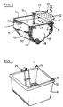
- the basket 6 is shown in Figure 3.
- This basket 6 is mounted on a shaft 8 fixed relative to the cooking vessel 9.
- the ends of this shaft 8 are for example introduced into openings 10.11 of ears 12 secured to the tank 9.
- the opening 10 is circular while the opening 11 has the shape a slot, so that the basket can be mounted in introducing one end of the shaft 8 into the opening 10 and then sliding the other end of the shaft in opening 11.
- the basket 6 has an upper edge 13 of rectangular shape and includes a bottom 18 and four openwork 14,15,16,17 sides, two side faces 16,17 perpendicular to the shaft 8, a front face 14 extending between the shaft 8 and a lower edge 19, and a rear face 15 extending between an upper edge and a lower edge 20, the bottom 18 extending between the lower edge 19 of the front face and the lower edge 20 of the rear face 15.
- the bottom 18 extends in an inclined plane of a angle ⁇ of 120 ° -125 ° from the plane in which extends the first face 14.
- the rear face 15 which, in a form of achievement may have the form of a sector of a cylinder, has an upper part 151 and a lower part 152 interconnected, said parts being arranged so that the edge upper, lower edge and intermediate edge 153 (located between the lower and upper parts) are located substantially at the same distance d by compared to tree 8.
- the basket 6 carries on the side of the shaft 8 a collector 21 intended to guide fried food out of the basket 6 to a receptacle.
- This collector 21 presents a plate 22 extending substantially in the extension of the plane in which the front face 14 extends. However, preferably, this dish 22 has an inclination ⁇ of 5 to 10 ° from the plane of the front face, so that the dish 22 overhangs the basket 6 when the latter is in the cooking vessel 9, the latter having heating resistors 99.
- the plate 22 has a substantially trapezoidal shape and is provided with lateral edges 23.
- the shaft 8 and the ears 10.11 of the tank 9 are arranged so that the shaft 8 extends above of tank 9, this allowing the liquid to cooking, for example oil or fat, falls back into the cooking vessel when basket 6 is lifted out of the tank 9.
- the additional ⁇ inclination allows a additional rotation of basket 6 is necessary to have the passage of fried food on the dish 22, this additional rotation allowing drainage extra fried food.
- the dish 22 has a series of orifices allowing additional oil drainage or fat located on fried or fried foods and a groove 24 extended by a dish 25 forming a chamber 26 open on the side of the shaft 8 to collect the oil or grease and guide this oil or fat into the tank when the basket 6 is in position to fill the basket 6 of food to fry or is in the pan (cooking position).
- the mechanism 5 to rotate the basket 6 around the shaft 8 comprises a crank 26 mounted on the shaft 29 driven by a motor 30 rotating in a one direction R, a crank 27 mounted on the shaft 8 of the basket 6 and a bar 28 connecting the said cranks 26.27 via pivots 31.32.
- the different positions cranks 26,27 and basket 6 are shown at Figures 5A to E and 6 A to E.
- the position of FIG. 6A corresponds to a position in which the basket 6 is above of the oil bath (the bottom 18 extending for example in a horizontal plane).
- the crank 27 extends in a direction forming an angle ⁇ A of 45 °, while the crank 26 extends in one direction forming an angle ⁇ A of 45 ° relative to the vertical axis V1 extending upwards from the shaft driven by engine.
- This position corresponds to the position of the basket 6 to load it with a portion of french fries fry.
- crank 27 turns in direction R so as to lower the basket 6 in the tank 9 to allow the cooking of food.
- FIGS. 5B and 6B show the position of the cranks and basket in lowered position.
- crank 27 extends in one direction forming an angle ⁇ B of 90 ° relative to the vertical V, while the crank 26 extends in one direction forming an angle ⁇ B of ⁇ 90 °. This amounts to saying that the cranks extend substantially in one plane horizontal.
- crank 26 In the position of FIG. 5C, the bottom 18 basket 6 located just above the oil bath, the crank 26 extends in a direction forming a angle ⁇ C of ⁇ 135 ° with respect to the vertical V, while that the crank 27 extends in a direction forming an angle ⁇ C of ⁇ 45 °.
- the fries can from this moment to drip.
- crank 26 When the crank 26 extends in a direction forming an angle ⁇ D of -90 ° relative to V1, the crank 27 extends in a direction forming a angle ⁇ D of -90 ° relative to V ( Figure 5D). In this position, the basket 6 has pivoted so that it does not overhangs the tank 9 more.
- the face 15 of the basket (opposite the adjacent face 14 of the shaft 8) is arranged relative to the tank so that the basket can be brought into the tank or removed from the tank and so that in the basket position in the tank, part of the face 15 is adjacent to the tank wall 9.
- Figure 7 schematically shows a smoke treatment device 7.
- a precapacitor 72 comprising a circuit 73 connected to a water supply 74 and to a landfill 75 and a wall 76 cooled by a supply 77 of fresh air, and a capacitor, for example with lamella 78.
- the fumes after condensation are then driven back into an ozonizer 79 comprising a series of 80 lamps before being driven back into the middle outside.
- a system 3 for loading a portion of food to be fried is shown in Figures 8A to C.
- the installation includes a housing 81 in which extends a tunnel container 82 mounted on a shaft 83 secured to the housing 81.
- the housing 81 has an upper opening 85 allowing the pivoting of the lid 84 of the container so as to open it, a side opening 86 extending from the vicinity of tree 83 to vicinity of edge bottom of container 82, and bottom wall 87 intended to be used to close the open bottom 88 of the container when cover 84 is in position opened.
- the tunnel container with a bottom or open end 88 put under the action of a spring 89 intended to bring back the container, in the absence of push P on its cover, in a position in which the wall 90 of the container hinged to the shaft 83 closes the lateral opening 86 of the housing 81.
- the mechanism 5 operating the basket is advantageously located outside the internal space 2 of the envelope 200.
- the front face 202 is provided with a seal 203 to ensure, when door 1 is in position closed, a seal.
- the cooking vessel 9 is placed on rails 204 and can be removed from the envelope 200 (door 1 open) by simple sliding. This allows a diaper easy to bowl 9 and basket 6 after removing them out of the envelope.
- the envelope 200 is provided with a security such as a lock that can only be released if the installation is energized and the temperature cooking oil or fat is below 50 ° C.
- the fan 70 causes suction of the fumes and vapors V outside chamber 2 of the enclosure 200.
- This envelope 200 has two side faces opposite 205,206, a background 207 and a ceiling 208. These bottom, ceiling and side faces have a wall 205A, 206A, 207A, 208A facing inward 2 of the envelope 200 and a wall 205B, 206B, 207B, 208B facing the outside of envelope 200. Between a wall facing inward 2 and a wall facing outward is defined a channel 205C, 206C, 20c, 208C by which fumes and vapors are drawn in V.
- the envelope has a window 218 located at the near ceiling 208 or at its ceiling and intended for form a passage between channel 205C and the chamber interior 2 of the envelope 200.
- the exhausted fumes and vapors therefore flow down (downward movement) in channel 205C, horizontally in channel 207C, upwards (upward movement) in channel 206C and horizontally in channel 208C.
- the fumes and vapors leaving channel 208C pass into the suction fan.
- the vapors are able to condense and condensation water trickle towards channel 207C from the bottom of the envelope.
- a heat exchanger 73 subjects the vapors passing through channel 207C to a cooling.
- V vapors which are substantially completely condensed at the outlet of the channel 208C are essentially condensed in the vicinity from the bottom 207 of the envelope 200, an important part even preponderant of the energy of the vapors is released at the bottom 207, so that at least the walls 207A and the side walls 205A, 206A in the vicinity of the bottom 207 are brought to a temperature sufficient to avoid any condensation of vapors thereon. In preventing such condensation in the envelope, allows the extraction device or fan suck all cooking vapors out of the envelope.
- the atmosphere of the envelope after a stage of cooking can be kept hot and with a relatively low moisture content, so that fried food left in the basket or in the receptacle inside the envelope 200 will remain hot. Since the receptacle is in the envelope 200 when it receives fried food, this receptacle is heated. This allows to keep still longer hot fried food.
- the installation is advantageously provided a security system.
- the rotation shaft 8 of the basket 6 and the pivot axis 83 of the tunnel container 82 are perpendicular between them.
- a lateral side 210 of the basket is used.
- the extension 21 serves as a stop to prevent or limit the pivoting of the tunnel.
- the extension 21 and wall 210 of the basket serve as stop preventing or limiting the pivoting of the tunnel 82.
- Preventing or limiting pivoting of tunnel 82 is therefore obtained thanks to the stop of the wall 90 of the tunnel or of its end 211 on the extension 21 or on the wall 210 of the basket 6.
- the wall 210 extends substantially in a plane perpendicular to the axis of the shaft 8, substantially parallel to the pivot axis of the tunnel 82. This ensures a substantially constant distance between said wall and the end 211 of wall 90 of tunnel and therefore maximum pivoting for tunnel 82.
- non-condensation of vapors at the interior of the envelope (2), the possibility and the easy cleaning, following installation the invention has a high degree of hygiene. Moreover non-condensation of vapors inside the envelope avoids corrosion problems, degradation of oil or grease, loss of energy (for example by condensation of vapors whose waters fall into the cooking vessel), less shock between the temperature of the oil or the grease and the temperature above the bath cooking, in particular during cooking phases, etc.
Landscapes
- Engineering & Computer Science (AREA)
- Food Science & Technology (AREA)
- Frying-Pans Or Fryers (AREA)
Description
- les figures 1 et 2 montrent schématiquement en perspective une installation suivant l'invention porte avant fermée et ouverte ;
- la figure 3 est une vue en perspective d'un panier ;
- la figure 4 est une vue en perspective d'une cuve ;
- les figures 5A à E montrent différentes étapes du mécanisme agissant sur le panier ;
- les figures 6A à E montrent les positions du panier par rapport à la cuve pour les étapes représentées aux figures 5A à E ;
- la figure 7 est une vue schématique d'un dispositif de traitement des fumées ;
- les figures 8A à C montrent des étapes du chargement d'une portion de frites dans le panier, et
- la figure 9 est une vue en coupe suivant la ligne IX-IX du panier montré à la figure 3.
- un moyen 70 d'aspiration des fumées hors de la chambre 2 et de refoulement des fumées, tel qu'un ventilateur; et
- un conduit 71 reliant la chambre 2 au moyen 70.
Claims (15)
- Installation pour frire des aliments, cette installation comprenant (a) une cuve (9), (b) un système comportant un panier (6), (c) un mécanisme (5) actionnant ledit système de manière à déplacer le panier (6) par rapport à la cuve (9) entre une position dans laquelle le panier est placé dans la cuve pour frire des aliments et une position dans laquelle le panier est hors de la cuve (9) pour amener les aliments fris dans un récipient, (d) un système pour introduire une portion d'aliments à frire dans le panier, et (e) une porte pour retirer le récipient dans lequel les aliments fris sont amenés, ladite installation comportant une enveloppe (200) définissant une chambre (2) dans laquelle se trouve la cuve (9) et un dispositif (7) pour extraire des fumées ou vapeurs, cette enveloppe comportant au voisinage de son fond (207) ou à son fond un ou plusieurs canaux à travers lesquels les ou des fumées ou vapeurs extraites passent et se condensent au moins partiellement, caractérisée en ce que le dispositif (7) extrait les fumées ou vapeurs hors de la chambre (2) de manière à ce qu'au moins partiellement l'énergie des fumées ou vapeurs soit récupérée pour chauffer l'enveloppe, et en ce que le système pour charger une portion d'aliments à frire dans un panier comporte un tunnel (82) présentant un couvercle (84) amovible ou monté à pivotement, ledit tunnel étant monté à pivotement dans un logement (81) présentant une première ouverture (85) pour permettre l'ouverture du couvercle (84) et une deuxième ouverture (86) pour permettre le passage des aliments à frire du tunnel (82) vers le panier (6), ledit tunnel (82) étant capable de pivoter entre, d'une part, une première position pour laquelle le tunnel (82) s'étend dans le logement pour empêcher le passage d'aliments à frire du tunnel (82) vers le panier (6) et pour introduire, lorsque le couvercle (84) est en position ouverte, une portion d'aliments à frire dans le tunnel (82), et, d'autre part, après fermeture du couvercle (84), une deuxième position pour introduire, via la deuxième ouverture (86), la portion d'aliments du tunnel (82) dans le panier (6).
- Installation suivant la revendication 1, caractérisée en ce que le tunnel (82) présente à son fond un passage (88), et en ce que le logement (81) présente une première ouverture (85) pour permettre l'ouverture du couvercle (84) du tunnel (82) et une deuxième ouverture (86) au travers de laquelle est engagée le passage (88) du fond du tunnel (82) pour introduire une portion d'aliments du tunnel (82) dans le panier (6), ledit logement (81) présentant une paroi (87) servant à obturer le passage (88) du tunnel (82) lors de l'introduction d'une portion d'aliments dans le tunnel (82), tandis que le tunnel (82) présente une paroi (90) servant à obturer la deuxième ouverture (86) lors de l'introduction d'une portion d'aliments dans le tunnel (82).
- Installation suivant la revendication 1 ou 2, caractérisée en ce que la chambre (2) présente un support (4) pour le récipient, de sorte que l'atmosphère chaude de la chambre (2) chauffe ledit récipient.
- Installation suivant l'une quelconque des revendications 1 à 3, caractérisée en ce que le fond (207) de l'enveloppe (200) présente deux parois (207A, 207B) séparées l'une de l'autre pour définir un canal (207C) au travers duquel les ou des fumées ou vapeurs extraites hors de la chambre (2) passent et se condensent au moins partiellement, de manière à ce qu'au moins partiellement l'énergie des fumées ou vapeurs soit récupérée pour chauffer le fond (207C) de l'enveloppe (200).
- Installation suivant la revendication 4, caractérisée en ce que l'enveloppe (200) présente au moins un côté latéral présentant deux parois (205A, 205B) séparées l'une de l'autre pour définir un canal (205C) s'etendant depuis une ouverture de la chambre (2) définie par l'enveloppe et située à un niveau au moins supérieur au bord supérieur de la cuve (9) jusqu'à une extrémité dudit canal (205C) par lequel il communique avec le canal (207C) défini par les parois (207A, 207B) du fond (207) de l'enveloppe (200).
- Installation suivant la revendication 4 ou 5, caractérisée en ce que l'enveloppe (200) présente un premier côté latéral à double parois (205A, 205B) entre lesquelles est défini un premier canal (205C), un fond (207) à double parois (207A,207B) entre lesquelles est défini un deuxième canal (207C) et un deuxième côté latéral à double parois (206A,206B) entre lesquelles est défini un troisième canal (206C), les fumées ou vapeurs extraites de la chambre (2) définie par l'enveloppe étant amenées par le dispositif d'extraction de fumées ou vapeurs (7) à se déplacer successivement vers le bas dans le premier canal (205C), ensuite sensiblement horizontalement dans le deuxième canal (207C) et enfin vers le haut dans le troisième canal (206C).
- Installation suivant l'une quelconque des revendications 4 à 6, caractérisée en ce que le dispositif de traitement des fumées et vapeurs (7) comporte un ozoneur (79).
- Installation suivant l'une quelconque des revendications précédentes, caractérisée en ce que l'enveloppe (200) présente une porte pour l'admission d'aliments à frire dans le panier et une porte pour retirer le récipient contenant des aliments fris hors de la chambre (2), lesdites portes étant agencées de manière à empêcher tout passage d'air dans la chambre (2) et à assurer que toutes les vapeurs ou fumées extraites de la chambre (2) passent par le ou des canaux de l'enveloppe (200).
- Installation suivant l'une quelconque des revendications 4 à 8, caractérisée en ce que le ou les canaux (207C) du fond (207) de l'enveloppe (200) servent de bac ou bassin de récupération d'eaux de condensation et présentent au moins un conduit d'évacuation d'eaux condensées, ledit ou desdits canaux (207C) du fond de l'enveloppe étant associés à un ou plusieurs échangeurs de chaleur (73) dans lesquels ou lequel circule un fluide.
- Installation suivant la revendication 9, caractérisée en ce que le ou les canaux (207C) du fond (207) de l'enveloppe (200) présente une amenée (77) d'air frais, cet air étant aspiré par le moyen d'extraction (70) des fumées et vapeurs hors de la chambre (2), ledit air frais agissant pour favoriser la condensation de vapeurs.
- Installation suivant l'une quelconque des revendications précédentes, cette installation comprenant un panier monté au voisinage d'un premier de ses bords sur un arbre (8) fixe par rapport à la cuve (9), le panier présentant une première face (14) adjacente audit arbre (8), une deuxième face (15) opposée à ladite première face (14), deux faces latérales (16,17) et un fond (18) s'étendant entre lesdites première et deuxième faces (14,15), la deuxième face (15) du panier (6) opposée à ladite première face (14) étant agencée par rapport à la cuve (9) de manière à ce que le panier (6) peut être amené par rotation dans la cuve (9), tandis que ledit fond (18) du panier (6) présente au moins une partie adjacente à la première face qui s'étend dans un plan incliné par rapport à ladite première face (14), ladite partie s'étendant dans un plan incliné par rapport à un plan horizontal lorsque le panier (6) est en position dans la cuve (9) pour frire des aliments, caractérisée en ce que l'inclinaison dudit plan incliné est telle que la partie du fond s'étendant dans celui-ci se trouve à un niveau situé sous le bord inférieur (19) de la première face (14), lorsque le panier (6) est en position dans la cuve (9) pour frire des aliments.
- Installation suivant la revendication 11, caractérisée en ce que l'inclinaison δ entre le plan dans lequel s'étend la première face (14) et le plan de la partie inclinée du fond (18) adjacente de la première face est supérieure à 100°, avantageusement supérieure à 110°, de préférence d'environ 120-125°.
- Installation suivant l'une quelconque des revendications 11 et 12, caractérisée en ce que le panier (6) présente un collecteur (21) situé dans le prolongement de la première face (14) et destiné à guider les aliments fris hors du panier (6) lorsque ce dernier est dans une position hors de la cuve (9), ledit collecteur (21) étant agencé de manière à ce qu'il surplombe le panier (6) lorsque ce dernier est dans la cuve de cuisson (9).
- Installation suivant l'une quelconque des revendication 11 à 13, caractérisée en ce que ladite partie inclinée du fond (18) qui est adjacente à la première face s'étend dans un plan formant un angle de 30 à 50° par rapport à un plan horizontal lorsque le panier (6) est dans la cuve (9) pour frire des aliments.
- Installation suivant l'une quelconque des revendications 11 à 14, caractérisée en ce que le mécanisme (5) comprend un moteur (30) entraínant en rotation uniquement dans un sens un arbre et un moyen pour convertir le mouvement de rotation de l'arbre en un mouvement alternatif, ledit moyen comprenant une manivelle (26) montée sur un arbre entraíné par le moteur (30), une manivelle (27) montée sur l'arbre (8) du panier (6), et une barre reliée à pivotement aux dites manivelles.
Applications Claiming Priority (3)
| Application Number | Priority Date | Filing Date | Title |
|---|---|---|---|
| FR9314085 | 1993-11-25 | ||
| FR9314085A FR2712791B1 (fr) | 1993-11-25 | 1993-11-25 | Installation de cuisson et panier pour une telle installation. |
| PCT/EP1994/003923 WO1995014417A1 (fr) | 1993-11-25 | 1994-11-25 | Installation de cuisson et panier pour une telle installation |
Publications (2)
| Publication Number | Publication Date |
|---|---|
| EP0730427A1 EP0730427A1 (fr) | 1996-09-11 |
| EP0730427B1 true EP0730427B1 (fr) | 2000-08-02 |
Family
ID=9453210
Family Applications (1)
| Application Number | Title | Priority Date | Filing Date |
|---|---|---|---|
| EP95903288A Expired - Lifetime EP0730427B1 (fr) | 1993-11-25 | 1994-11-25 | Installation de cuisson et panier pour une telle installation |
Country Status (4)
| Country | Link |
|---|---|
| EP (1) | EP0730427B1 (fr) |
| DE (1) | DE69425440T2 (fr) |
| FR (1) | FR2712791B1 (fr) |
| WO (1) | WO1995014417A1 (fr) |
Families Citing this family (6)
| Publication number | Priority date | Publication date | Assignee | Title |
|---|---|---|---|---|
| US6516711B1 (en) * | 1999-10-29 | 2003-02-11 | Patatas Chef, S.L. | Semiautomatic deep frier with fume and smell purifiers |
| EP2272385B1 (fr) | 2007-06-21 | 2014-05-14 | Electrolux Home Products Corporation N.V. | Four de cuisson comprenant des moyens d'oxygénation et son procédé de fonctionnement |
| JP7092967B2 (ja) * | 2017-11-03 | 2022-06-29 | 上海愛餐機器人(集団)有限公司 | 調理機油煙処理システムと調理機 |
| CN110671732B (zh) * | 2017-11-03 | 2021-07-02 | 上海爱餐机器人(集团)有限公司 | 烹饪设备的油烟处理系统 |
| CN111237954A (zh) * | 2018-11-29 | 2020-06-05 | 宁波方太厨具有限公司 | 一种空调式集成灶系统 |
| CN112089313B (zh) * | 2020-09-08 | 2021-09-24 | 南京金燃节能科技有限公司 | 一种节能型厨房海鲜智能蒸柜 |
Family Cites Families (15)
| Publication number | Priority date | Publication date | Assignee | Title |
|---|---|---|---|---|
| LU62322A1 (fr) * | 1970-10-29 | 1971-05-18 | ||
| DE2451130C3 (de) * | 1974-10-28 | 1980-10-23 | Bosch-Siemens Hausgeraete Gmbh, 7000 Stuttgart | Dampfdruckgargerät für Speisen |
| FR2491031A1 (fr) * | 1980-09-30 | 1982-04-02 | Gideco | Appareil de distribution de produits en vrac, notamment de frites chaudes |
| FR2556576B1 (fr) * | 1983-12-14 | 1987-01-09 | Seb Sa | Hublot pour appareil menager de cuisson avec dispositif anti-buee |
| FR2593626B1 (fr) * | 1986-01-27 | 1988-03-11 | Beauvalet Christelle | Distributeur autimatique ou semi-automatique de portions alimentaires chaudes a partir de produits congeles par exemple frites ou autres feculents et de produits frais a base de viande, poisson ou autres |
| IT1202549B (it) * | 1987-02-13 | 1989-02-09 | Valerio Falavigna | Distributore automatico di cibi fritti con depuratore dei fumi di cottura |
| FR2629329A1 (fr) * | 1988-04-05 | 1989-10-06 | Veyret Ets | Machine a frire les aliments |
| IT1220389B (it) * | 1988-05-31 | 1990-06-15 | Gilberto Ripatonda | Macchina perfezionata per la preparazione di una serie di alimenti fritti,e per la distribuzione immediata di tale serie |
| EP0380816A1 (fr) * | 1989-02-01 | 1990-08-08 | C.T.A. S.a.s. di CONCA G. & C. | Procédé et machine de friture et de distribution automatique d'aliments frits |
| US5003868A (en) * | 1989-05-01 | 1991-04-02 | Alperk Limited | Food processing apparatus |
| JPH0719304B2 (ja) * | 1989-07-06 | 1995-03-06 | 東広島ゴルフ振興株式会社 | 自動フライ販売装置 |
| US5133786A (en) * | 1990-01-26 | 1992-07-28 | Anderson Edward M | Method and apparatus for minimizing odor during hot oil food cooking |
| FR2672409A1 (fr) * | 1991-02-06 | 1992-08-07 | Techni Concept International | Dispositif pour la distribution de portions de produits alimentaires extraites d'un stock en vrac de produits a cuire. |
| FR2684282B1 (fr) * | 1991-12-03 | 1995-03-17 | Seb Sa | Appareil de cuisson a ventilation forcee. |
| SE501130C2 (sv) * | 1992-03-09 | 1994-11-21 | Bengt H Hansson | Varmluftsugn för matberedning i hetluft med kylning av ytor och kontroll av ånghalt |
-
1993
- 1993-11-25 FR FR9314085A patent/FR2712791B1/fr not_active Expired - Fee Related
-
1994
- 1994-11-25 WO PCT/EP1994/003923 patent/WO1995014417A1/fr not_active Ceased
- 1994-11-25 DE DE69425440T patent/DE69425440T2/de not_active Expired - Fee Related
- 1994-11-25 EP EP95903288A patent/EP0730427B1/fr not_active Expired - Lifetime
Also Published As
| Publication number | Publication date |
|---|---|
| WO1995014417A1 (fr) | 1995-06-01 |
| FR2712791B1 (fr) | 1996-01-19 |
| EP0730427A1 (fr) | 1996-09-11 |
| FR2712791A1 (fr) | 1995-06-02 |
| DE69425440D1 (de) | 2000-09-07 |
| DE69425440T2 (de) | 2001-03-29 |
Similar Documents
| Publication | Publication Date | Title |
|---|---|---|
| CA1181961A (fr) | Friteuse industrielle a cuve de friture obturable hermetiquement | |
| EP3785582A1 (fr) | Appareil de cuisson a air chaud avec un encombrement reduit dans une configuration de rangement | |
| CA3173004C (fr) | Appareil de cuisson electrique | |
| EP0262275B1 (fr) | Dispositif de nettoyage pour le siège d'une cuvette de cabinet d'aisances | |
| EP0234996A1 (fr) | Distributeur de produits alimentaires | |
| EP1006849B1 (fr) | Appareil de cuisson electrique comportant un dispositif de condensation des vapeurs de cuisson | |
| EP0730427A1 (fr) | Installation de cuisson et panier pour une telle installation | |
| FR2614090A3 (fr) | Appareil mobile de climatisation de locaux | |
| WO1991004698A1 (fr) | Dispositif pour appareil de cuisson d'aliments et appareil de cuisson muni d'un tel dispositif | |
| FR2912302A1 (fr) | Dispositif de regulation du niveau d'eau d'une cavite chauffante d'un appareil electromenager | |
| FR2887420A1 (fr) | Cuiseur a panier de cuisson mobile, comportant un detecteur de debut de cuisson | |
| CN100356882C (zh) | 烹饪和分发食品的装置 | |
| EP1180648B1 (fr) | hotte de cuisine motorisée | |
| EP0112263B1 (fr) | Friteuse à circulation d'huile | |
| EP4371450B1 (fr) | Appareil de cuisson comprenant un dispositif de collecte configure pour collecter des jus de cuisson et des condensats | |
| EP3785584A1 (fr) | Appareil de cuisson a air chaud muni d'une embase de reception d'un recipient de cuisson et d'un dispositif de verrouillage entre le recipient et l'embase | |
| FR2887418A1 (fr) | Cuiseur a panier de cuisson, comportant un systeme pour eviter la formation de mousse | |
| BE1012477A7 (fr) | Appareil de cuisson. | |
| FR2652999A1 (fr) | Dispositif de vidange du contenu d'une cuve basculante d'un appareil de cuisson. | |
| BE1007582A5 (fr) | Friteuse electrique en particulier pour applications domestiques. | |
| FR2640359A1 (fr) | Four pour la cuisson de produits alimentaires, notamment pour la cuisson des frites | |
| FR2933288A1 (fr) | Appareil de cuisson comportant un dispositif de filtration de vapeurs de cuisson ameliore | |
| FR2806589A1 (fr) | Appareil de torrefaction | |
| BE1009202A6 (fr) | Panier pour appareil de cuisson. | |
| FR2661085A1 (fr) | Friteuse automatique a cuve fermee. |
Legal Events
| Date | Code | Title | Description |
|---|---|---|---|
| PUAI | Public reference made under article 153(3) epc to a published international application that has entered the european phase |
Free format text: ORIGINAL CODE: 0009012 |
|
| 17P | Request for examination filed |
Effective date: 19960504 |
|
| AK | Designated contracting states |
Kind code of ref document: A1 Designated state(s): BE DE FR GB |
|
| 17Q | First examination report despatched |
Effective date: 19971215 |
|
| GRAG | Despatch of communication of intention to grant |
Free format text: ORIGINAL CODE: EPIDOS AGRA |
|
| GRAG | Despatch of communication of intention to grant |
Free format text: ORIGINAL CODE: EPIDOS AGRA |
|
| GRAG | Despatch of communication of intention to grant |
Free format text: ORIGINAL CODE: EPIDOS AGRA |
|
| GRAH | Despatch of communication of intention to grant a patent |
Free format text: ORIGINAL CODE: EPIDOS IGRA |
|
| GRAH | Despatch of communication of intention to grant a patent |
Free format text: ORIGINAL CODE: EPIDOS IGRA |
|
| GRAA | (expected) grant |
Free format text: ORIGINAL CODE: 0009210 |
|
| RAP1 | Party data changed (applicant data changed or rights of an application transferred) |
Owner name: INTERMESURES, SOCIETE ANONYME |
|
| RIN1 | Information on inventor provided before grant (corrected) |
Inventor name: GARCIA, FERNAND |
|
| AK | Designated contracting states |
Kind code of ref document: B1 Designated state(s): BE DE FR GB |
|
| REF | Corresponds to: |
Ref document number: 69425440 Country of ref document: DE Date of ref document: 20000907 |
|
| GBT | Gb: translation of ep patent filed (gb section 77(6)(a)/1977) |
Effective date: 20001026 |
|
| PLBE | No opposition filed within time limit |
Free format text: ORIGINAL CODE: 0009261 |
|
| STAA | Information on the status of an ep patent application or granted ep patent |
Free format text: STATUS: NO OPPOSITION FILED WITHIN TIME LIMIT |
|
| 26N | No opposition filed | ||
| PGFP | Annual fee paid to national office [announced via postgrant information from national office to epo] |
Ref country code: GB Payment date: 20011108 Year of fee payment: 8 |
|
| PGFP | Annual fee paid to national office [announced via postgrant information from national office to epo] |
Ref country code: BE Payment date: 20011113 Year of fee payment: 8 |
|
| PGFP | Annual fee paid to national office [announced via postgrant information from national office to epo] |
Ref country code: FR Payment date: 20011129 Year of fee payment: 8 |
|
| PGFP | Annual fee paid to national office [announced via postgrant information from national office to epo] |
Ref country code: DE Payment date: 20011227 Year of fee payment: 8 |
|
| REG | Reference to a national code |
Ref country code: GB Ref legal event code: IF02 |
|
| PG25 | Lapsed in a contracting state [announced via postgrant information from national office to epo] |
Ref country code: GB Free format text: LAPSE BECAUSE OF NON-PAYMENT OF DUE FEES Effective date: 20021125 |
|
| PG25 | Lapsed in a contracting state [announced via postgrant information from national office to epo] |
Ref country code: BE Free format text: LAPSE BECAUSE OF NON-PAYMENT OF DUE FEES Effective date: 20021130 |
|
| BERE | Be: lapsed |
Owner name: S.A. *INTERMESURES Effective date: 20021130 |
|
| PG25 | Lapsed in a contracting state [announced via postgrant information from national office to epo] |
Ref country code: DE Free format text: LAPSE BECAUSE OF NON-PAYMENT OF DUE FEES Effective date: 20030603 |
|
| GBPC | Gb: european patent ceased through non-payment of renewal fee | ||
| PG25 | Lapsed in a contracting state [announced via postgrant information from national office to epo] |
Ref country code: FR Free format text: LAPSE BECAUSE OF NON-PAYMENT OF DUE FEES Effective date: 20030731 |
|
| REG | Reference to a national code |
Ref country code: FR Ref legal event code: ST |