EP0730428B1 - Scanning ophthalmoscope - Google Patents
Scanning ophthalmoscope Download PDFInfo
- Publication number
- EP0730428B1 EP0730428B1 EP95900822A EP95900822A EP0730428B1 EP 0730428 B1 EP0730428 B1 EP 0730428B1 EP 95900822 A EP95900822 A EP 95900822A EP 95900822 A EP95900822 A EP 95900822A EP 0730428 B1 EP0730428 B1 EP 0730428B1
- Authority
- EP
- European Patent Office
- Prior art keywords
- scanning
- eye
- ophthalmoscope
- mirror
- focus
- Prior art date
- Legal status (The legal status is an assumption and is not a legal conclusion. Google has not performed a legal analysis and makes no representation as to the accuracy of the status listed.)
- Expired - Lifetime
Links
- 210000001525 retina Anatomy 0.000 claims abstract description 26
- 238000000034 method Methods 0.000 claims description 13
- 210000001747 pupil Anatomy 0.000 claims description 10
- 201000009310 astigmatism Diseases 0.000 abstract description 14
- 230000003287 optical effect Effects 0.000 description 15
- 230000001179 pupillary effect Effects 0.000 description 14
- 230000002207 retinal effect Effects 0.000 description 14
- 210000000695 crystalline len Anatomy 0.000 description 12
- 238000003384 imaging method Methods 0.000 description 12
- 230000006870 function Effects 0.000 description 10
- 238000013461 design Methods 0.000 description 9
- 230000007246 mechanism Effects 0.000 description 9
- 238000012937 correction Methods 0.000 description 6
- 230000033001 locomotion Effects 0.000 description 6
- 238000004519 manufacturing process Methods 0.000 description 6
- 239000004065 semiconductor Substances 0.000 description 6
- 238000005286 illumination Methods 0.000 description 5
- 230000006872 improvement Effects 0.000 description 5
- 230000004256 retinal image Effects 0.000 description 5
- 230000004075 alteration Effects 0.000 description 4
- 238000012545 processing Methods 0.000 description 4
- 230000000712 assembly Effects 0.000 description 3
- 238000000429 assembly Methods 0.000 description 3
- 230000008901 benefit Effects 0.000 description 3
- 230000001427 coherent effect Effects 0.000 description 3
- 210000004087 cornea Anatomy 0.000 description 3
- 238000001514 detection method Methods 0.000 description 3
- 239000007789 gas Substances 0.000 description 3
- 238000007493 shaping process Methods 0.000 description 3
- 230000001360 synchronised effect Effects 0.000 description 3
- 238000003491 array Methods 0.000 description 2
- 230000008859 change Effects 0.000 description 2
- 239000003086 colorant Substances 0.000 description 2
- 239000002131 composite material Substances 0.000 description 2
- 238000010226 confocal imaging Methods 0.000 description 2
- 230000007812 deficiency Effects 0.000 description 2
- 238000010586 diagram Methods 0.000 description 2
- 201000010099 disease Diseases 0.000 description 2
- 208000037265 diseases, disorders, signs and symptoms Diseases 0.000 description 2
- 239000000835 fiber Substances 0.000 description 2
- 230000002441 reversible effect Effects 0.000 description 2
- 238000001429 visible spectrum Methods 0.000 description 2
- 206010012689 Diabetic retinopathy Diseases 0.000 description 1
- 208000010412 Glaucoma Diseases 0.000 description 1
- 208000006550 Mydriasis Diseases 0.000 description 1
- 208000002367 Retinal Perforations Diseases 0.000 description 1
- 206010038848 Retinal detachment Diseases 0.000 description 1
- 230000002411 adverse Effects 0.000 description 1
- 230000003321 amplification Effects 0.000 description 1
- XKRFYHLGVUSROY-UHFFFAOYSA-N argon Substances [Ar] XKRFYHLGVUSROY-UHFFFAOYSA-N 0.000 description 1
- 229910052786 argon Inorganic materials 0.000 description 1
- 239000003638 chemical reducing agent Substances 0.000 description 1
- 230000006835 compression Effects 0.000 description 1
- 238000007906 compression Methods 0.000 description 1
- 238000013481 data capture Methods 0.000 description 1
- 238000002405 diagnostic procedure Methods 0.000 description 1
- 230000000694 effects Effects 0.000 description 1
- 238000005516 engineering process Methods 0.000 description 1
- 230000004424 eye movement Effects 0.000 description 1
- 238000001914 filtration Methods 0.000 description 1
- 210000003128 head Anatomy 0.000 description 1
- CPBQJMYROZQQJC-UHFFFAOYSA-N helium neon Chemical compound [He].[Ne] CPBQJMYROZQQJC-UHFFFAOYSA-N 0.000 description 1
- 238000010191 image analysis Methods 0.000 description 1
- 238000010348 incorporation Methods 0.000 description 1
- 238000003331 infrared imaging Methods 0.000 description 1
- 230000007257 malfunction Effects 0.000 description 1
- 238000000386 microscopy Methods 0.000 description 1
- 230000004048 modification Effects 0.000 description 1
- 238000012986 modification Methods 0.000 description 1
- 231100000989 no adverse effect Toxicity 0.000 description 1
- 238000003199 nucleic acid amplification method Methods 0.000 description 1
- 230000037361 pathway Effects 0.000 description 1
- 201000007914 proliferative diabetic retinopathy Diseases 0.000 description 1
- 238000005086 pumping Methods 0.000 description 1
- 230000010344 pupil dilation Effects 0.000 description 1
- 230000004044 response Effects 0.000 description 1
- 230000004283 retinal dysfunction Effects 0.000 description 1
- 230000006641 stabilisation Effects 0.000 description 1
- 230000003068 static effect Effects 0.000 description 1
- 230000000699 topical effect Effects 0.000 description 1
- 238000012876 topography Methods 0.000 description 1
- 238000012549 training Methods 0.000 description 1
Images


Classifications
-
- A—HUMAN NECESSITIES
- A61—MEDICAL OR VETERINARY SCIENCE; HYGIENE
- A61B—DIAGNOSIS; SURGERY; IDENTIFICATION
- A61B3/00—Apparatus for testing the eyes; Instruments for examining the eyes
- A61B3/10—Objective types, i.e. instruments for examining the eyes independent of the patients' perceptions or reactions
- A61B3/1025—Objective types, i.e. instruments for examining the eyes independent of the patients' perceptions or reactions for confocal scanning
Definitions
- the invention relates to a scanning ophthalmoscope for scanning the retina of the eye.
- the need for a wide field retinal imaging ophthalmoscope is based on the fact that current fundus camera designs can produce high quality film based images in colour, but are limited in their field of view of the object plane to a maximum of 60 degrees from the pupillary point. Many manufacturers in fact produce less than the 60 degree field of view.
- Scanning laser ophthalmoscopes currently produce a 40 degree field of view in true monochrome or synthesised (not true) colour images.
- the resolution of the scanned laser-based images may be two to three orders of magnitude less than the film based images, but the advantage of the scanning laser ophthalmoscope is that dynamic images are available for display on standard television monitors. These images may be recorded on standard video tape.
- the field of view of both film based cameras and scanning laser ophthalmoscopes may be artificially increased by rotating the camera about a specific centre of rotation, lying between the rear surface of the cornea and the front surface of the lens, the so-called "pupillary point".
- an instrument which produces complete wide field images in one scan, without mechanical machine movement, is valuable in producing more efficient diagnostic information for the clinician.
- High resolution of the scanning laser ophthalmoscope image enhances interpretation of fine detail, while the production of the image in colour in such an instrument would assist in the clinical diagnostic process particularly for certain diseases such as proliferative diabetic retinopathy.
- the three types may be classified by the manufacturers' names viz;
- This system scans the retina of the eye through the use of a tilted spherical mirror.
- X and Y scans are produced by means of a high speed rotating polygon, and an oscillating galvanometer mirror.
- Laser beams of wave lengths corresponding to Argon ion (488nm), Helium Neon (566nm) and Infra-red (790nm) are focused through a manually variable focusing system to produce a best image.
- the scanning system produces pixel image data, by means of an electronic detector system, synchronised with the scanning mirrors to produce data at video rate output.
- the signal is electronically processed (not through a framestore) to produce an image which is capable of being displayed on an ordinary television monitor. They system is therefore capable of real time dynamic imaging.
- the Heidelburg Scanning Laser Tomograph is a laser based scanning design, specifically utilised for examination of the optic disc.
- the machine is used clinically to diagnose and assess the progress of the disease glaucoma.
- the instrument delivers laser light through a fibre optic light guide to the X and Y scanning units which are high speed opto-acoustic deflectors.
- the field of scan is limited to about 5 degrees, centred on the optic disc, and the scan angle is limited by the pupil of the eye since the centre of scan rotation is external to the eye, and not centred on the pupillary point.
- the instrument is incapable of wide field retinal imaging in a single scan.
- the instrument produces a colour display of the topography of the optic disc.
- the colours represent differing height levels rather than tissue colour, and so this display is a synthesised image and not a true colour rendition.
- a flat surface is therefore only imaged as a single colour plane.
- the instrument is therefore not a true retinal imaging instrument, and is unable to produce wide field retinal images in representative tissue colour.
- the prime function of this instrument is to produce topographic representations of the retina.
- the Zeiss system is a semi-hybrid version of the Rodenstock and Heidelburg instruments.
- a spherical mirror is used to increase the scan angle of the instrument by utilising the pupillary point, and the X and Y scans are performed by rotating polygon and galvanometer driven mirrors respectively.
- the Zeiss utilises fibre-optic incident laser light delivery and returned light conduits to connect to the main instrument processing body.
- the Zeiss contains only manually controlled patient optics compensation, and also, as for both the Rodenstock and Heidelburg designs, utilises a confocal imaging system to reject unwanted data from the required data returned signal. The use of a confocal detection system enhances the quality of the returned data, rejecting spurious information.
- Confocal imaging is utilised in many areas of microscopy, and is a feature of all the instruments detailed above.
- WO-A-90/00026 An apparatus having the features referred to in the pre-characterising portion of Claim 1 is disclosed in WO-A-90/00026. This document addresses the problem of correcting the trapezoidal distortion encountered when examining the fundus of the eye in a known way.
- US-A-4755044 describes a system for forming and viewing a single enlarged imate of a selected region of an eye.
- EP-A-0412667 discloses an ophthalmoscope which uses a separate flesh illumination system and photo detector to detect light reflected from an eye fundus, for processing.
- EP-A-0223356 discloses means for producing a conjugate image of the pupil of an eye at a point where a detector may be placed.
- This invention seeks to provide a scanning laser ophthalmoscope for wide field scanning of the retina of the eye.
- the invention is also directed to a method by which the described apparatus operates, and includes method steps for carrying out every function of the apparatus.
- the design set out here defines the implementation of a wide field retinal scanning ophthalmoscope with colour imaging capability that seeks to improve on or eliminate deficiencies of the current designs of scanning laser ophthalmoscopes. To achieve this, it is necessary to look at the implementation of a design which not only has novelty from both electro-optic and mechanical viewpoints, but also addresses the question of the fundamental limitations and imaging qualities of the eye at the extremes of the field of view. No current scanning laser ophthalmoscope is capable of producing images at the extremes of the field of view due to the generalised nature of existing designs for imaging on the central axis of the eye.
- a scanning ophthalmoscope for scanning the retina of an eye, having a laser light source and an aspherical mirror in the path of the light from the light source wherein the light is reflected from the aspherical mirror for incidence with the retina of the eye, and as recited in claim 1.
- the aspherical mirror is ellipsoidal.
- the ophthalmoscope includes a means for producing a two dimensional scan.
- the means for producing a two dimensional scan may include a rotating mechanism and an oscillating mechanism.
- the rotating mechanism is a rotating polygon reflector scanner and the oscillating mechanism is a galvanometer scanner.
- the means for producing a two dimensional scan act with a non-transmissive scanning compensator to provide a virtual point which is coincident with one focus of the ellipsoidal mirror.
- the non-transmissive scanning compensator may be a scanning prism. Alternatively, it may be an arrangement of an off-axis aspheric mirror and a galvanometer or a rotating polygon.
- the rotating polygon reflector scanner may be positioned prior to the galvanometer scanner in the path of the incident beam from the light source.
- the ellipsoidal mirror is orientated such that the sagittal focus is shorter than the tangential focus, ie the sagittal focus point is in front of the tangential focus point.
- the ophthalmoscope includes an active control mechanism to vary astigmatism compensation during a retinal scan cycle.
- the astigmatism compensation may be varied in accordance with the data of a return beam after incidence with the retina.
- compensation means are provided in the form of an assembly of short focal length optics which compensation means are adjusted in relation to the active control mechanism.
- the compensation means are arranged to act on the incident and return beams.
- the ophthalmoscope includes a focus compensation which is active during a scan of the retina which focus compensation compensates for distorted retinal surfaces and/or the refractive nature of the eye.
- the laser light source is a semi conductor diode laser.
- the ellipsoidal mirror is either a front surface mirror or a combined reflective/refractive mirror.
- a method of scanning a retina of an eye comprising directing a laser light onto a retina via an aspherical mirror, and as recited in claim 6.
- means are provided for producing an area scan of the retina.
- a scanning ophthalmoscope 2 is used for the production of images of the rear surface of the human eye and specifically of the retina, using a method of scanning multiple laser beams with and through optical systems, utilising scanners, mirrors and optical components to produce digitised (pixelated) images which maybe displayed and stored in industry standard computer systems.
- the inventions and improvements claimed in this implementation relate to improvements in scanning and imaging technologies to compensate for both eye and machine optical errors and aberrations.
- Substantial improvements to proprietary scanning methods for the production of accurate pixelated images with adequate resolution and contrast are detailed (Figs 2 and 3), as is the incorporation of dynamic (active feedback) systems for the compensation of spherical focus and residual astigmatisms.
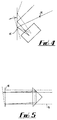
- a method of compensating for errors in the scanners is outlined (Fig 4) as is a method of increasing beam scan angles by optical means (Fig 5) rather than mechanical means.
- a method of producing digital colour images is detailed, and the essential invention and improvements over existing scanning laser ophthalmoscopes in terms of high field angles (wide field of view at the retina) relating to image resolution is characterised.
- infra-red camera system for operator guidance with no adverse patient impact is described, and the use of infra-red imaging for ophthalmoscope positioning, with a secondary function of eye movement detection is also included.
- the use of infra-red light has no adverse effect on the pupil response of the eye.
- a patient target system is proposed. This will assist the patient with the positioning of the eye, and will also allow the clinical specialist to predict the area of the eye which is actually imaging for the patient. This function is particularly useful when determining ophthalmic errors in young patients.
- Coherent laser light at selected wavelengths is produced and directed from a first 4, second 6 and third 8 laser source into a common incident beam 16 through a first 12 and second 14 dichroic beam splitter.
- the coherent laser sources 4,6,8 are so selected that incident beam 16 which exits the second dichroic beam splitter 14 is essentially 'white' light at low powers.
- Means of colour balancing the lasers from laser sources 4,6,8 for optimum imaging is achieved through first 18, second 20 and third 22 power control filters.
- a third dichroic beamsplitter 24 has two functions. The first function is that the incident light a proportion of the energy is split off into a power monitor 26 which utilises a photo detector which has suitable filters to monitor the individual lasers from laser sources 4,6,8. The outputs of these detectors is monitored electronically, provides safe level operation and, in the case of malfunction, would cause machine shut down by means of an electrically operated safety shutter 28.
- the second function of the third dichroic beamsplitter 24 is to separate the energy returned from the eye by the scanners, and pass this to a focusing lens 30, a confocal aperture 32 (of variable aperture diameter and variable spacing from the detector) and a multiplicity of filters and detectors 34 to produce electronic signal outputs for the returned colour signal levels simultaneously.
- a single detector may be used and each colour scanned sequentially, rather than simultaneously, at a loss of image data capture speed.
- the collimated beams pass to first 36 and second 38 dynamic compensation elements.
- the first dynamic compensation element 36 controls the off-axis astigmatism of the eye and the second dynamic compensation element 38 controls the focus during the scan of the retina.
- These dynamic compensation elements 36,38 are beam shaping lens assemblies of short focal length optics controlled by piezo actuators, which allow high speed compensation drive motions to be imported to the optics assemblies. Offsets to both the focus and astigmatic correction assemblies can be applied manually for individual patient correction. Dynamic control will utilise feedback in terms of the retinal spot size, which will be detected at a defocus position of the returned image point which will be detected by a fourth dichroic beam splitter 40 and an array detector 42.
- the incident beam 16 is then directed to a scanning transmissive prism 44 whose functions is to eliminate cross-scan error at the scan, or pupillary, point of the eye.
- the scanning prism 44 acts to give lateral shift to the incident beam 16 before further directing said beam on to the reflecting surface of a galvanometer scanner 46.
- Use of this scanning prism 44 means that the incident beam 16 presents at the surface of the rotating polygon 48 as a virtual point source.
- the galvanometer scanner 46 provides a vertical scanning motion of the incident beam 16. The speed of this galvanometer 46 determines the frame rate.
- the incident beam 16 is directed onto a rotating polygon reflector scanner 48 which provides a horizontal scanning motion of the incident beam 16.
- the relative positions of the galvanometer scanner 46 and the polygonal scanner 48 in the path of the incident beam 16 are the reverse of their relative positions described in known prior art. This arrangement allows the rotating polygon reflector scanner 48 to deliver a two dimensional angular scan from an apparent or virtual point source.
- An implementation may be made where the relative positions of the galvanometer scanner 46 and polygon scanner 48 are reversed.
- a galvanometer or rotating polygon may be used in conjunction with an off-axis aspheric reflective surface mirror, or such a form that a scanned angular incident or input beam is reflected by the mirror such that all beams returned from the mirror are parallel for all angles of input beam from the scanning point.
- Such a form of mirror could be an off-axis paraboloid.
- This implementation would form the basis of a none transmissive virtual point scanning system for a one dimensional scanner.
- other aspheric forms could be used for scanning.
- the replacement of a scanning prism requires the addition of both a mirror and a scanning galvanometer or rotating prism, in addition to the galvanometer and rotating polygon for the two dimensional scan of the scanning laser ophthalmoscope.
- the incident beam 16 is then directed onto an aspheric mirror 50 which is used to direct and shape the scanning beam at the pupillary point of the eye 52 of the subject.
- the incident beam enters the eye 52 through the pupil.
- the reflected beam which may have a diameter 5-10 times that of the incident beam 16, is initially directed back along the optical path common with that of the incident beam 16.
- This reflected beam is collected by the aspheric or ellipsoidal mirror 50 which directs it via the rotating polygon detector scanner 48 and the galvanometer scanner 46 to the scanning prism 44.
- the scanning prism 44 acts to compensate for the lateral shift of the reflected beam before the reflected beam reaches the dynamic focus compensation elements 36,38.
- This compensation de-scans the return beam, and ensures the return beam is co-incident with the incident beam 16 at the third dichroic beamsplitter 24 thus optimising the data signal of the reflected beam before it is registered by the image data detector 22 at the confocal aperture 32, scanned, used to produce a retinal image and then stored in data arrays for further processing.
- the confocal aperture 32 is confocal with the retinal plane under examination, and seeks to eliminate spurious returned data from the retina, and therefore allows only the scanned pixel under consideration to be imaged, so improving contrast of adjacent pixels.
- the laser can be any laser light source which provides emission at suitable frequencies. Employment of single wavelength laser illumination produces monochromatic images. However, the production of colour images may be synthesised by scanning using multiple laser beams of varying wavelengths covering the visible spectrum and utilizing wavelengths approximating to the three primary colours of light; red, green and blue. The specific wavelengths in the red, green and blue bands 566 mm, 633 mm and 488 mm will give composite colour images.
- the low average power of illumination required for the laser scan of the retina in a patient means that laser wavelengths in the visible regions are acceptable without undue patient discomfort even without the use of topical mydriasis, (eye pupil dilation), and may be combined into a 'white light' beam for fast scanning.
- the laser (coherent) light production may be by several means. Gas lasers may be used, and give good collimated light beams of small diameter without additional correction optics.
- Semiconductor diode lasers may be used in various forms, either with direct light production, or utilising "pumping" techniques to produce higher harmonics, which with suitable filtering would allow coverage of the visible spectrum (450 nm - 800 nm). Delivery of the laser energy may he directly from gas lasers, from semiconductor diodes through beam shaping optics to compensate for the natural astigmatism of the laser diodes, or though fibre optic delivery systems incorporating collimating optics, which would allow the laser diodes to be positioned away from the scanning head if desired.
- Ophthalmic consultants are used to assessing general retinal dysfunctions through the use of colour, and the intention of this new retinal scanning laser ophthalmoscope is to produce an instrument which requires little specialist training for use in image analysis.
- this ophthalmoscope utilises semiconductor diode laser devices for incident beam scanning.
- An advantage of semiconductor diode lasers is their capability of very fast modulation of the output beam, and this high rate of modulation of the output beam gives this design a further advantage over prior art.
- Known inventions require that the raster produced by this scanning beam be separately modulated by a beam deflector or modulator since gas lasers cannot be modulated by on/off switching.
- This separate optomodulator could be a source of beam distortion and so its removal from the device can only be an improvement.
- the semiconductor diode lasers allow modification of the raster scans to produce patient image targets. Suitable software will allow the position of the image target to be overlaid on the retinal image and so allow easier stabilisation of the eye of the difficult subject. Small children may be attracted by the use of simple cartoon images.
- a fundamental component of the proposed design is an ellipsoidal mirror.
- Existing ophthalmoscopes incorporating mirrors specify that said mirrors be spherical whilst acknowledging the aberrations inherent in spherical mirrors when so utilised.
- Said mirrors in this context are referred to as retro-scanning mirrors.
- a method considered when improving the field of view of scanning laser ophthalmoscopes is to do so by increasing the size of the retro-scanning mirror.
- the scanning mirror is chosen specifically to be aspheric in order to optimise the optical path length and to ensure that the scanning mirror allows compensation of the scanned beam across its surface, in accordance with the compensation required to accommodate the natural astigmatism of the eye at the wider angles of view.
- the ellipsoidal mirror has two focal points.
- the incident beam scan is introduced to the mirror through one focus, and the mirror uses the second focus point for directing the scanned illumination beam within the eye, thus allowing the retina to be covered by the scanning beam in two dimensions.
- the eye is approximately spherical and the pupillary point (or focus point) of the aspheric mirror is located within the optical structure of the eye, it is necessary to determine a novel method to compensate for astigmatic beam aberrations during retinal scanning.
- the astigmatic correction of any scanning beam in the pupillary point entails a change of optical power along differential axes as the scan progresses from the central axis of the eye to the periphery of the retina.
- Existing scanning laser ophthalmoscopes do not address this problem.
- the maximum field of view available is about 38° as seen from the pupillary point.
- the scan axis of the mirror is rotated relative to the central axis of the eye.
- the disadvantage of this is that as the scan axis rotation increases a proportion of the image field of the instrument defocuses due to astigmatism and/or defocus and the image produced becomes less informative. Additionally, the instrument presents only the scan data of the image view set by the instrument at any one time, and no means exist to store views and present a composite image with this system.
- the next step is to introduce mechanisms to adjust the focus during scanning in order to obtain wide field digital data with "one pass" scanning.
- the idea is to use a focusing telescope, driven by piezo-electric elements, to compensate for these image variations.
- the piezo electric elements operating at a sufficiently high speed to allow such execution within the scan cycle, will optimise the image by electronic closed loop feedback from the image data detection and associated electronics.
- the scan point traverses laterally across the facets of the mirror as it rotates. This scan point movement, caused by the fact that the centre of rotation is not a point at the centre of rotation of the front face of the mirror, causes loss of data on the return beam.
- the returned data beam has diameter 5-10 times that of the incident beam. Unless compensated for, this can lead to loss of about 80% of the returned beam due to a combination of the fact that the returned beam may overfill the polygon scan mirrors and that this will allow data to be lost as the edges of the mirror facets traverse the beam.
- the astigmatic compensation mechanism will consist of an assembly of very short focal length optics installed in the incident optical pathway before the scanning of the incident beam.
- This beam shaping lens assembly will act to focus the incident beam to optimise the illuminated spot on the retina thus controlling the resolution of the image, by means of computer controlled small relative movements of the piezo driven optics in the assembly.
- the beam will thus be optimised by computer control of the lens assembly operating at rates of compensation similar to those of the active focusing telescope control.
- the same compensations will act on the returned data beams before it is registered by the image data detector. In this direction, the assembly will focus the return beam at the confocal aperture thus determining the contrast of the final image registered.
- the image data detectors which are photoelectric will produce pixel points of a retinal image of wide field of view and high resolution.
- the pixel points will form the data and will be stored in a frame grabber array at the maximum resolution of the scanner 54 and the monitor 56 used for display will not limit the data contained to that providing the image frame.
- the monitor will be used to 'pan' through the total image in high resolution mode.
- a further refinement is the use of fractal compression techniques to compress the data and provide a complete image at lower resolution - analogous to the 'zoom' lens.
- the data is then stored in arrays, on hard or optical disc, for further processing.
- the laser scanning ophthalmoscope is proposed to be enclosed in an enclosure arrangement whereby the subject will place the head (therefore the eye) in the position to be scanned. This entails that the consultant is unable to see directly the position of the scanning laser beams within the pupil of the eye of the subject.
- a patient eye positioning system is therefore proposed using an infra-red area illumination.
- An infrared area illuminator 58 is directed through a power isolator and reducer filter 60, and fifth 62 and sixth 64 dichroic beamsplitters to illuminate the front of the eye.
- the returned image is passed through dichroic filters 64, 62 to a infra-red band pass filter 66 and the image received by a small charge coupled device camera 68, and the image displayed on a small video monitor.
- the incident beam from the scanner system will be easily viewed and the operator will be able to place the incident beam in the plane of the pupil 52 of the subject.
- the "Virtual Point Scanning” system is a special case of the general case, of "Addressable Point Scanning", whereby two scanning prisms are used in an orthogonal manner and the speed of one prism is synchronised or varied with respect to the rotation of the rotating polygon and the other scanning prism is synchronised or varied with respect to the galvanometer mirror.
- This addressable scan point may be allowed to track within the pupillary plane.
- Virtual Point Scan is a specialist case where only one scanning prism is used in conjunction with the galvanometer drive, and allows the beam angle scan within the pupillary plane to appear to come from one source, the virtual point.
- the pupillary point is an arbitrary point within the lens system of the eye, through which all the scan rays should be made to pass, in order to optimise the wide angle capability of the instrument.
- Virtual point scanning seeks to ensure that this is undertaken.
Landscapes
- Life Sciences & Earth Sciences (AREA)
- Health & Medical Sciences (AREA)
- Surgery (AREA)
- Biophysics (AREA)
- Ophthalmology & Optometry (AREA)
- Engineering & Computer Science (AREA)
- Biomedical Technology (AREA)
- Heart & Thoracic Surgery (AREA)
- Medical Informatics (AREA)
- Molecular Biology (AREA)
- Physics & Mathematics (AREA)
- Animal Behavior & Ethology (AREA)
- General Health & Medical Sciences (AREA)
- Public Health (AREA)
- Veterinary Medicine (AREA)
- Eye Examination Apparatus (AREA)
- Ultra Sonic Daignosis Equipment (AREA)
- Endoscopes (AREA)
- Measurement Of Optical Distance (AREA)
- Investigating, Analyzing Materials By Fluorescence Or Luminescence (AREA)
- Mechanical Optical Scanning Systems (AREA)
- Microscoopes, Condenser (AREA)
Applications Claiming Priority (3)
| Application Number | Priority Date | Filing Date | Title |
|---|---|---|---|
| GB939323065A GB9323065D0 (en) | 1993-11-09 | 1993-11-09 | A wide field retinal scanning ophthalmoscope |
| GB9323065 | 1993-11-09 | ||
| PCT/GB1994/002465 WO1995013012A2 (en) | 1993-11-09 | 1994-11-09 | Scanning ophthalmoscope |
Publications (2)
| Publication Number | Publication Date |
|---|---|
| EP0730428A1 EP0730428A1 (en) | 1996-09-11 |
| EP0730428B1 true EP0730428B1 (en) | 1999-09-01 |
Family
ID=10744863
Family Applications (1)
| Application Number | Title | Priority Date | Filing Date |
|---|---|---|---|
| EP95900822A Expired - Lifetime EP0730428B1 (en) | 1993-11-09 | 1994-11-09 | Scanning ophthalmoscope |
Country Status (10)
| Country | Link |
|---|---|
| US (1) | US5815242A (da) |
| EP (1) | EP0730428B1 (da) |
| JP (1) | JP3490088B2 (da) |
| AT (1) | ATE183910T1 (da) |
| AU (1) | AU8148594A (da) |
| DE (1) | DE69420427T2 (da) |
| DK (1) | DK0730428T3 (da) |
| ES (1) | ES2138177T3 (da) |
| GB (1) | GB9323065D0 (da) |
| WO (1) | WO1995013012A2 (da) |
Cited By (1)
| Publication number | Priority date | Publication date | Assignee | Title |
|---|---|---|---|---|
| US8346345B2 (en) | 2004-01-21 | 2013-01-01 | University Of Washington | Methods for assessing a physiological state of a mammalian retina |
Families Citing this family (70)
| Publication number | Priority date | Publication date | Assignee | Title |
|---|---|---|---|---|
| US5777719A (en) | 1996-12-23 | 1998-07-07 | University Of Rochester | Method and apparatus for improving vision and the resolution of retinal images |
| US5867251A (en) * | 1997-05-02 | 1999-02-02 | The General Hospital Corp. | Scanning ophthalmoscope with spatial light modulators |
| FR2769721B1 (fr) * | 1997-10-10 | 2001-01-26 | Sextant Avionique | Dispositif optique pour viseur de casque comportant un miroir de mangin |
| CN1157153C (zh) * | 1998-11-24 | 2004-07-14 | 威尔驰阿林公司 | 不扩瞳观察视网膜检眼装置 |
| US6186628B1 (en) * | 1999-05-23 | 2001-02-13 | Jozek F. Van de Velde | Scanning laser ophthalmoscope for selective therapeutic laser |
| US6244712B1 (en) | 1999-09-27 | 2001-06-12 | University Of Alabama In Huntsville | Optical scanning spectroscopic apparatus and associated method |
| US6550917B1 (en) * | 2000-02-11 | 2003-04-22 | Wavefront Sciences, Inc. | Dynamic range extension techniques for a wavefront sensor including use in ophthalmic measurement |
| US7331669B2 (en) * | 2001-10-16 | 2008-02-19 | Indiana University Research And Technology Corporation | Device for digital retinal imaging |
| US20030103191A1 (en) * | 2001-11-06 | 2003-06-05 | Ocular Instruments, Inc. | Wide angle lens for use with a scanning laser ophthalmoscope |
| DE20306542U1 (de) * | 2003-04-25 | 2003-08-28 | Oculus Optikgeräte GmbH, 35582 Wetzlar | Vorrichtung zur Projektion eines Lichtstrahls |
| US20050157260A1 (en) * | 2003-11-12 | 2005-07-21 | Graham Raymond D. | Lens for producing stereoscopic images |
| DE102004053660B4 (de) * | 2004-11-03 | 2013-01-17 | Marius Jurca | Verfahren zur berührungslosen Erfassung von geometrischen Eigenschaften einer Objektoberfläche |
| US8488895B2 (en) * | 2006-05-31 | 2013-07-16 | Indiana University Research And Technology Corp. | Laser scanning digital camera with pupil periphery illumination and potential for multiply scattered light imaging |
| GB2440163A (en) * | 2006-07-15 | 2008-01-23 | Optos Plc | Scanning ophthalmoscope with reduced shear distortion |
| GB0622325D0 (en) * | 2006-11-09 | 2006-12-20 | Optos Plc | Improvements in or relating to retinal scanning |
| JP4829765B2 (ja) * | 2006-12-08 | 2011-12-07 | キヤノン株式会社 | 画像表示装置及び画像表示システム |
| JP2009086366A (ja) * | 2007-09-28 | 2009-04-23 | Brother Ind Ltd | 光走査装置、光走査型画像表示装置及び網膜走査型画像表示装置 |
| US20090161196A1 (en) * | 2007-12-20 | 2009-06-25 | Barco Nv | System and method for speckle reduction from a coherent light source in a projection device |
| US20090174867A1 (en) * | 2008-01-08 | 2009-07-09 | Barco Nv | System and method for reducing image artifacts in a projection device using a scrolling refractive element |
| RU2373834C1 (ru) * | 2008-05-13 | 2009-11-27 | Андрей Александрович Сосновский | Офтальмоскоп налобный бинокулярный |
| EP2306889A4 (en) * | 2008-07-10 | 2012-11-28 | Univ Indiana Res & Tech Corp | OPHTHALMIC APPARATUS, SYSTEMS AND METHODS |
| US20100245765A1 (en) * | 2008-10-28 | 2010-09-30 | Dyer Holdings, Llc | Video infrared ophthalmoscope |
| JP5242454B2 (ja) * | 2009-03-02 | 2013-07-24 | 株式会社ニデック | 眼科撮影装置 |
| JP5676856B2 (ja) * | 2009-05-08 | 2015-02-25 | キヤノン株式会社 | 補償光学系を備えた画像取得装置 |
| GB0913911D0 (en) * | 2009-08-10 | 2009-09-16 | Optos Plc | Improvements in or relating to laser scanning systems |
| WO2011022488A2 (en) | 2009-08-18 | 2011-02-24 | University Of Memphis Research Foundation | Systems, methods, and computer-readable media for detecting and predicting a progression of retinal pathologies |
| GB201007046D0 (en) | 2010-04-28 | 2010-06-09 | Optos Plc | Improvements in or relating to scanning ophthalmoscopes |
| GB201011096D0 (en) * | 2010-07-01 | 2010-08-18 | Optos Plc | Improvements in or relating to ophthalmology |
| GB201011095D0 (en) | 2010-07-01 | 2010-08-18 | Optos Plc | Improvements in or relating to ophthalmology |
| GB201011094D0 (en) * | 2010-07-01 | 2010-08-18 | Optos Plc | Improvements in or relating to ophthalmology |
| US9510974B1 (en) | 2010-10-13 | 2016-12-06 | Gholam A. Peyman | Laser coagulation of an eye structure or a body surface from a remote location |
| US12502074B2 (en) | 2010-10-13 | 2025-12-23 | Gholam A. Peyman | Telemedicine system with dynamic imaging |
| US8452372B2 (en) | 2010-10-13 | 2013-05-28 | Gholam Peyman | System for laser coagulation of the retina from a remote location |
| US10456209B2 (en) | 2010-10-13 | 2019-10-29 | Gholam A. Peyman | Remote laser treatment system with dynamic imaging |
| US9931171B1 (en) | 2010-10-13 | 2018-04-03 | Gholam A. Peyman | Laser treatment of an eye structure or a body surface from a remote location |
| US9037217B1 (en) | 2010-10-13 | 2015-05-19 | Gholam A. Peyman | Laser coagulation of an eye structure or a body surface from a remote location |
| US11309081B2 (en) | 2010-10-13 | 2022-04-19 | Gholam A. Peyman | Telemedicine system with dynamic imaging |
| US8903468B2 (en) | 2010-10-13 | 2014-12-02 | Gholam Peyman | Laser coagulation of an eye structure from a remote location |
| GB201100555D0 (en) * | 2011-01-13 | 2011-03-02 | Optos Plc | Improvements in or relating to Ophthalmology |
| EP2701574B1 (en) | 2011-04-27 | 2017-02-15 | Carl Zeiss Meditec AG | Ultra wide-field optical coherence tomography |
| GB201209390D0 (en) | 2012-05-28 | 2012-07-11 | Optos Plc | Improvements in or relating to image processing |
| GB201217538D0 (en) * | 2012-10-01 | 2012-11-14 | Optos Plc | Improvements in or relating to scanning laser ophthalmoscopes |
| DE102012022967A1 (de) | 2012-11-21 | 2014-05-22 | Carl Zeiss Meditec Ag | Reflexfreies, optisches System für eine Funduskamera |
| WO2014124470A1 (en) * | 2013-02-11 | 2014-08-14 | Lifelens, Llc | System, method and device for automatic noninvasive screening for diabetes and pre-diabetes |
| DE102013218416B4 (de) | 2013-09-13 | 2022-10-06 | Carl Zeiss Meditec Ag | Reflexfreies Ophthalmoskopobjektiv |
| JP6528933B2 (ja) * | 2014-12-26 | 2019-06-12 | 株式会社ニデック | 眼底撮影装置 |
| JP2015205176A (ja) | 2014-04-08 | 2015-11-19 | 株式会社トプコン | 眼科装置 |
| US10799111B2 (en) | 2014-06-10 | 2020-10-13 | Carl Zeiss Meditec, Inc. | Frequency-domain interferometric based imaging systems and methods |
| JP6040216B2 (ja) * | 2014-12-25 | 2016-12-07 | キヤノン株式会社 | 補償光学系を備えた画像取得装置 |
| WO2016103489A1 (ja) | 2014-12-26 | 2016-06-30 | 株式会社ニコン | 眼底像形成装置 |
| WO2016103484A1 (ja) * | 2014-12-26 | 2016-06-30 | 株式会社ニコン | 眼底像形成装置 |
| EP3150109B1 (en) * | 2015-09-30 | 2023-07-05 | Nidek Co., Ltd. | Fundus imaging device |
| JP6734642B2 (ja) | 2015-12-18 | 2020-08-05 | 株式会社トプコン | 眼科装置 |
| US10201275B1 (en) | 2016-02-09 | 2019-02-12 | Carl Zeiss Meditec, Inc. | Reflective ultra-wide field fundus imager |
| US9978140B2 (en) | 2016-04-26 | 2018-05-22 | Optos Plc | Retinal image processing |
| US10010247B2 (en) | 2016-04-26 | 2018-07-03 | Optos Plc | Retinal image processing |
| JP6819773B2 (ja) | 2016-09-06 | 2021-01-27 | 株式会社ニコン | 反射屈折等倍アフォーカル瞳孔リレー及びこれを採用した光学撮影系 |
| JP2018061621A (ja) | 2016-10-11 | 2018-04-19 | オプトス ピーエルシー | 眼底画像撮影装置、眼底画像撮影方法、及び眼底画像撮影プログラム |
| JP2018061622A (ja) | 2016-10-11 | 2018-04-19 | オプトス ピーエルシー | 眼底観察装置 |
| CN106388765B (zh) * | 2016-11-09 | 2018-06-05 | 苏州微清医疗器械有限公司 | 超广角眼底成像系统 |
| JP6824837B2 (ja) | 2017-07-05 | 2021-02-03 | 株式会社トプコン | 眼科装置 |
| WO2019034231A1 (en) | 2017-08-14 | 2019-02-21 | Optos Plc | TRACKING RETINAL POSITION |
| US11669968B2 (en) | 2017-08-14 | 2023-06-06 | Optos Plc | Ophthalmic device |
| JP7395803B2 (ja) | 2017-08-14 | 2023-12-12 | オプトス ピーエルシー | 眼科装置 |
| JP7162553B2 (ja) | 2019-02-27 | 2022-10-28 | 株式会社トプコン | 眼科情報処理装置、眼科装置、眼科情報処理方法、及びプログラム |
| ES2892477T3 (es) | 2019-04-04 | 2022-02-04 | Optos Plc | Dispositivo de formación de imágenes médicas |
| ES2923585T3 (es) | 2019-10-01 | 2022-09-28 | Optos Plc | Dispositivo de obtención de imágenes oftálmicas |
| US11568540B2 (en) | 2019-10-07 | 2023-01-31 | Optos Plc | System, method, and computer-readable medium for rejecting full and partial blinks for retinal tracking |
| ES2917214T3 (es) | 2019-10-07 | 2022-07-07 | Optos Plc | Sistema de formación de imágenes oftálmicas |
| CN112220448B (zh) * | 2020-10-14 | 2022-04-22 | 北京鹰瞳科技发展股份有限公司 | 眼底相机及眼底图像合成方法 |
Family Cites Families (13)
| Publication number | Priority date | Publication date | Assignee | Title |
|---|---|---|---|---|
| US4213678A (en) * | 1977-09-29 | 1980-07-22 | Retina Foundation | Scanning ophthalmoscope for examining the fundus of the eye |
| DE3245939C2 (de) * | 1982-12-11 | 1985-12-19 | Fa. Carl Zeiss, 7920 Heidenheim | Vorrichtung zur Erzeugung eines Bildes des Augenhintergrundes |
| US4768873A (en) * | 1985-09-17 | 1988-09-06 | Eye Research Institute Of Retina Foundation | Double scanning optical apparatus and method |
| US4765730A (en) * | 1985-09-17 | 1988-08-23 | Eye Research Institute Of Retina Foundation | Double scanning optical apparatus and method |
| JPH07121254B2 (ja) * | 1985-09-17 | 1995-12-25 | アイ・リサ−チ・インステイテユ−ト・オブ・ザ・レテイナ・フアウンデイシヨン | 2重走査光学装置 |
| US4764005A (en) * | 1985-09-17 | 1988-08-16 | Eye Research Institute Of Retina Foundation | Double scanning optical apparatus |
| US4755044A (en) * | 1986-01-06 | 1988-07-05 | Massachusetts Institute Of Technology | Remote ophthalmoscope and fundus photography unit |
| US4768874A (en) * | 1987-09-10 | 1988-09-06 | Eye Research Institute Of Retina Foundation | Scanning optical apparatus and method |
| DE3821973A1 (de) * | 1988-06-29 | 1990-02-08 | Rodenstock Instr | Vorrichtung zur erzeugung eines bildes eines objekts (iii) |
| US4893920A (en) * | 1988-08-09 | 1990-01-16 | Eye Research Institute Of Retina Foundation | Optical scanning system and method including correction for cross scan error |
| JPH0357425A (ja) * | 1989-07-26 | 1991-03-12 | Kowa Co | 眼底検査装置 |
| DE4101356A1 (de) * | 1991-01-18 | 1992-07-23 | Zeiss Carl Fa | Ophthalmoskop |
| JP3157550B2 (ja) * | 1991-02-28 | 2001-04-16 | 株式会社リコー | 等速光走査用結像反射鏡および光走査装置 |
-
1993
- 1993-11-09 GB GB939323065A patent/GB9323065D0/en active Pending
-
1994
- 1994-11-09 DE DE69420427T patent/DE69420427T2/de not_active Expired - Lifetime
- 1994-11-09 ES ES95900822T patent/ES2138177T3/es not_active Expired - Lifetime
- 1994-11-09 AT AT95900822T patent/ATE183910T1/de not_active IP Right Cessation
- 1994-11-09 WO PCT/GB1994/002465 patent/WO1995013012A2/en not_active Ceased
- 1994-11-09 EP EP95900822A patent/EP0730428B1/en not_active Expired - Lifetime
- 1994-11-09 JP JP51368495A patent/JP3490088B2/ja not_active Expired - Fee Related
- 1994-11-09 US US08/640,913 patent/US5815242A/en not_active Expired - Lifetime
- 1994-11-09 AU AU81485/94A patent/AU8148594A/en not_active Abandoned
- 1994-11-09 DK DK95900822T patent/DK0730428T3/da active
Cited By (1)
| Publication number | Priority date | Publication date | Assignee | Title |
|---|---|---|---|---|
| US8346345B2 (en) | 2004-01-21 | 2013-01-01 | University Of Washington | Methods for assessing a physiological state of a mammalian retina |
Also Published As
| Publication number | Publication date |
|---|---|
| ATE183910T1 (de) | 1999-09-15 |
| DE69420427T2 (de) | 2000-05-04 |
| WO1995013012A3 (en) | 1995-08-31 |
| US5815242A (en) | 1998-09-29 |
| GB9323065D0 (en) | 1994-01-05 |
| ES2138177T3 (es) | 2000-01-01 |
| JP3490088B2 (ja) | 2004-01-26 |
| AU8148594A (en) | 1995-05-29 |
| WO1995013012A2 (en) | 1995-05-18 |
| DK0730428T3 (da) | 2000-03-27 |
| EP0730428A1 (en) | 1996-09-11 |
| JPH09509337A (ja) | 1997-09-22 |
| DE69420427D1 (de) | 1999-10-07 |
Similar Documents
| Publication | Publication Date | Title |
|---|---|---|
| EP0730428B1 (en) | Scanning ophthalmoscope | |
| US4764005A (en) | Double scanning optical apparatus | |
| US4768873A (en) | Double scanning optical apparatus and method | |
| EP0223356B1 (en) | Two-dimensional eye fundus scanning apparatus | |
| US5258791A (en) | Spatially resolved objective autorefractometer | |
| JP2618912B2 (ja) | 眼底検査装置 | |
| EP0691103B1 (en) | Opthalmologic apparatus for fundus imaging | |
| US5949520A (en) | Wide field of view scanning laser ophthalmoscope | |
| CA2881936C (en) | Improvements in or relating to scanning laser ophthalmoscopes | |
| RU2675688C2 (ru) | Хирургическая система визуализации oct широкого поля обзора без использования микроскопа | |
| KR100339259B1 (ko) | 안구 망막의 3차원 실시간 영상화 장치 | |
| US20130194548A1 (en) | Portable retinal imaging device | |
| JPS59115024A (ja) | 眼底像を形成する方法および装置 | |
| US20030218755A1 (en) | Optical coherence tomography optical scanner | |
| CN103750814A (zh) | 一种眼底扫描成像装置 | |
| WO2005048829A2 (en) | Ophthalmic binocular wafefront measurement system | |
| JP2016510628A (ja) | 携帯型網膜画像化装置 | |
| JP6494385B2 (ja) | 光画像撮像装置及びその制御方法 | |
| CN113842108A (zh) | 用于眼底视网膜的成像系统 | |
| JP2019010239A (ja) | 眼科用顕微鏡 | |
| JP2021153786A (ja) | 画像処理装置、画像処理方法及びプログラム | |
| CN119700010A (zh) | 一种免调焦椭球面眼底成像系统 | |
| JP2018126548A (ja) | 眼科手術装置 |
Legal Events
| Date | Code | Title | Description |
|---|---|---|---|
| PUAI | Public reference made under article 153(3) epc to a published international application that has entered the european phase |
Free format text: ORIGINAL CODE: 0009012 |
|
| 17P | Request for examination filed |
Effective date: 19960427 |
|
| AK | Designated contracting states |
Kind code of ref document: A1 Designated state(s): AT BE CH DE DK ES FR GB GR IE IT LI LU MC NL PT SE |
|
| AX | Request for extension of the european patent |
Free format text: LT PAYMENT 960427;SI PAYMENT 960427 |
|
| RAX | Requested extension states of the european patent have changed |
Free format text: LT PAYMENT 960427;SI PAYMENT 960427 |
|
| RAP3 | Party data changed (applicant data changed or rights of an application transferred) |
Owner name: OPTOS LIMITED |
|
| 17Q | First examination report despatched |
Effective date: 19970417 |
|
| RAP1 | Party data changed (applicant data changed or rights of an application transferred) |
Owner name: OPTOS PUBLIC LIMITED COMPANY |
|
| GRAG | Despatch of communication of intention to grant |
Free format text: ORIGINAL CODE: EPIDOS AGRA |
|
| GRAG | Despatch of communication of intention to grant |
Free format text: ORIGINAL CODE: EPIDOS AGRA |
|
| GRAH | Despatch of communication of intention to grant a patent |
Free format text: ORIGINAL CODE: EPIDOS IGRA |
|
| GRAH | Despatch of communication of intention to grant a patent |
Free format text: ORIGINAL CODE: EPIDOS IGRA |
|
| GRAA | (expected) grant |
Free format text: ORIGINAL CODE: 0009210 |
|
| AK | Designated contracting states |
Kind code of ref document: B1 Designated state(s): AT BE CH DE DK ES FR GB GR IE IT LI LU MC NL PT SE |
|
| AX | Request for extension of the european patent |
Free format text: LT PAYMENT 19960427;SI PAYMENT 19960427 |
|
| LTIE | Lt: invalidation of european patent or patent extension | ||
| PG25 | Lapsed in a contracting state [announced via postgrant information from national office to epo] |
Ref country code: SE Free format text: THE PATENT HAS BEEN ANNULLED BY A DECISION OF A NATIONAL AUTHORITY Effective date: 19990901 Ref country code: GR Free format text: LAPSE BECAUSE OF NON-PAYMENT OF DUE FEES Effective date: 19990901 Ref country code: BE Free format text: LAPSE BECAUSE OF FAILURE TO SUBMIT A TRANSLATION OF THE DESCRIPTION OR TO PAY THE FEE WITHIN THE PRESCRIBED TIME-LIMIT Effective date: 19990901 Ref country code: AT Free format text: LAPSE BECAUSE OF FAILURE TO SUBMIT A TRANSLATION OF THE DESCRIPTION OR TO PAY THE FEE WITHIN THE PRESCRIBED TIME-LIMIT Effective date: 19990901 |
|
| REF | Corresponds to: |
Ref document number: 183910 Country of ref document: AT Date of ref document: 19990915 Kind code of ref document: T |
|
| REG | Reference to a national code |
Ref country code: CH Ref legal event code: EP |
|
| REF | Corresponds to: |
Ref document number: 69420427 Country of ref document: DE Date of ref document: 19991007 |
|
| REG | Reference to a national code |
Ref country code: IE Ref legal event code: FG4D |
|
| PG25 | Lapsed in a contracting state [announced via postgrant information from national office to epo] |
Ref country code: LU Free format text: LAPSE BECAUSE OF NON-PAYMENT OF DUE FEES Effective date: 19991109 Ref country code: IE Free format text: LAPSE BECAUSE OF NON-PAYMENT OF DUE FEES Effective date: 19991109 |
|
| ITF | It: translation for a ep patent filed | ||
| PG25 | Lapsed in a contracting state [announced via postgrant information from national office to epo] |
Ref country code: PT Free format text: LAPSE BECAUSE OF FAILURE TO SUBMIT A TRANSLATION OF THE DESCRIPTION OR TO PAY THE FEE WITHIN THE PRESCRIBED TIME-LIMIT Effective date: 19991202 |
|
| ET | Fr: translation filed | ||
| REG | Reference to a national code |
Ref country code: CH Ref legal event code: NV Representative=s name: KIRKER & CIE SA |
|
| REG | Reference to a national code |
Ref country code: ES Ref legal event code: FG2A Ref document number: 2138177 Country of ref document: ES Kind code of ref document: T3 |
|
| REG | Reference to a national code |
Ref country code: DK Ref legal event code: T3 |
|
| PG25 | Lapsed in a contracting state [announced via postgrant information from national office to epo] |
Ref country code: MC Free format text: LAPSE BECAUSE OF NON-PAYMENT OF DUE FEES Effective date: 20000531 |
|
| PLBQ | Unpublished change to opponent data |
Free format text: ORIGINAL CODE: EPIDOS OPPO |
|
| PLBI | Opposition filed |
Free format text: ORIGINAL CODE: 0009260 |
|
| 26 | Opposition filed |
Opponent name: WECO-WERNICKE & CO. GMBH Effective date: 20000531 |
|
| REG | Reference to a national code |
Ref country code: IE Ref legal event code: MM4A |
|
| NLR1 | Nl: opposition has been filed with the epo |
Opponent name: WECO-WERNICKE & CO. GMBH |
|
| PLBF | Reply of patent proprietor to notice(s) of opposition |
Free format text: ORIGINAL CODE: EPIDOS OBSO |
|
| PLBF | Reply of patent proprietor to notice(s) of opposition |
Free format text: ORIGINAL CODE: EPIDOS OBSO |
|
| REG | Reference to a national code |
Ref country code: GB Ref legal event code: IF02 |
|
| PLBP | Opposition withdrawn |
Free format text: ORIGINAL CODE: 0009264 |
|
| PLBL | Opposition procedure terminated |
Free format text: ORIGINAL CODE: EPIDOS OPPC |
|
| PLBM | Termination of opposition procedure: date of legal effect published |
Free format text: ORIGINAL CODE: 0009276 |
|
| STAA | Information on the status of an ep patent application or granted ep patent |
Free format text: STATUS: OPPOSITION PROCEDURE CLOSED |
|
| 27C | Opposition proceedings terminated |
Effective date: 20021202 |
|
| NLR2 | Nl: decision of opposition |
Effective date: 20021202 |
|
| PG25 | Lapsed in a contracting state [announced via postgrant information from national office to epo] |
Ref country code: IT Free format text: LAPSE BECAUSE OF NON-PAYMENT OF DUE FEES Effective date: 20091109 |
|
| PGRI | Patent reinstated in contracting state [announced from national office to epo] |
Ref country code: IT Effective date: 20110616 |
|
| PGFP | Annual fee paid to national office [announced via postgrant information from national office to epo] |
Ref country code: DK Payment date: 20121122 Year of fee payment: 19 |
|
| PGFP | Annual fee paid to national office [announced via postgrant information from national office to epo] |
Ref country code: CH Payment date: 20121120 Year of fee payment: 19 |
|
| PGFP | Annual fee paid to national office [announced via postgrant information from national office to epo] |
Ref country code: IT Payment date: 20121126 Year of fee payment: 19 |
|
| PGFP | Annual fee paid to national office [announced via postgrant information from national office to epo] |
Ref country code: ES Payment date: 20121126 Year of fee payment: 19 |
|
| PGFP | Annual fee paid to national office [announced via postgrant information from national office to epo] |
Ref country code: FR Payment date: 20131031 Year of fee payment: 20 Ref country code: GB Payment date: 20131118 Year of fee payment: 20 Ref country code: DE Payment date: 20131120 Year of fee payment: 20 |
|
| PGFP | Annual fee paid to national office [announced via postgrant information from national office to epo] |
Ref country code: NL Payment date: 20131118 Year of fee payment: 20 |
|
| REG | Reference to a national code |
Ref country code: DK Ref legal event code: EBP Effective date: 20131130 |
|
| REG | Reference to a national code |
Ref country code: CH Ref legal event code: PL |
|
| PG25 | Lapsed in a contracting state [announced via postgrant information from national office to epo] |
Ref country code: LI Free format text: LAPSE BECAUSE OF NON-PAYMENT OF DUE FEES Effective date: 20131130 Ref country code: CH Free format text: LAPSE BECAUSE OF NON-PAYMENT OF DUE FEES Effective date: 20131130 |
|
| PG25 | Lapsed in a contracting state [announced via postgrant information from national office to epo] |
Ref country code: IT Free format text: LAPSE BECAUSE OF NON-PAYMENT OF DUE FEES Effective date: 20131109 |
|
| PG25 | Lapsed in a contracting state [announced via postgrant information from national office to epo] |
Ref country code: DK Free format text: LAPSE BECAUSE OF NON-PAYMENT OF DUE FEES Effective date: 20131130 |
|
| REG | Reference to a national code |
Ref country code: DE Ref legal event code: R071 Ref document number: 69420427 Country of ref document: DE |
|
| REG | Reference to a national code |
Ref country code: NL Ref legal event code: V4 Effective date: 20141109 |
|
| REG | Reference to a national code |
Ref country code: GB Ref legal event code: PE20 Expiry date: 20141108 |
|
| PG25 | Lapsed in a contracting state [announced via postgrant information from national office to epo] |
Ref country code: GB Free format text: LAPSE BECAUSE OF EXPIRATION OF PROTECTION Effective date: 20141108 |
|
| REG | Reference to a national code |
Ref country code: ES Ref legal event code: FD2A Effective date: 20150406 |
|
| PG25 | Lapsed in a contracting state [announced via postgrant information from national office to epo] |
Ref country code: ES Free format text: LAPSE BECAUSE OF NON-PAYMENT OF DUE FEES Effective date: 20131110 |