EP0730541B1 - Systeme de direction assistee pour vehicule - Google Patents
Systeme de direction assistee pour vehicule Download PDFInfo
- Publication number
- EP0730541B1 EP0730541B1 EP94929031A EP94929031A EP0730541B1 EP 0730541 B1 EP0730541 B1 EP 0730541B1 EP 94929031 A EP94929031 A EP 94929031A EP 94929031 A EP94929031 A EP 94929031A EP 0730541 B1 EP0730541 B1 EP 0730541B1
- Authority
- EP
- European Patent Office
- Prior art keywords
- rotating member
- rotating
- steering system
- power steering
- members
- Prior art date
- Legal status (The legal status is an assumption and is not a legal conclusion. Google has not performed a legal analysis and makes no representation as to the accuracy of the status listed.)
- Expired - Lifetime
Links
- 239000012530 fluid Substances 0.000 claims description 7
- 230000015572 biosynthetic process Effects 0.000 description 3
- 238000004519 manufacturing process Methods 0.000 description 2
- 238000012986 modification Methods 0.000 description 1
- 230000004048 modification Effects 0.000 description 1
- 230000007935 neutral effect Effects 0.000 description 1
- 230000035945 sensitivity Effects 0.000 description 1
Images





Classifications
-
- B—PERFORMING OPERATIONS; TRANSPORTING
- B62—LAND VEHICLES FOR TRAVELLING OTHERWISE THAN ON RAILS
- B62D—MOTOR VEHICLES; TRAILERS
- B62D5/00—Power-assisted or power-driven steering
- B62D5/06—Power-assisted or power-driven steering fluid, i.e. using a pressurised fluid for most or all the force required for steering a vehicle
- B62D5/08—Power-assisted or power-driven steering fluid, i.e. using a pressurised fluid for most or all the force required for steering a vehicle characterised by type of steering valve used
- B62D5/083—Rotary valves
-
- B—PERFORMING OPERATIONS; TRANSPORTING
- B62—LAND VEHICLES FOR TRAVELLING OTHERWISE THAN ON RAILS
- B62D—MOTOR VEHICLES; TRAILERS
- B62D5/00—Power-assisted or power-driven steering
- B62D5/06—Power-assisted or power-driven steering fluid, i.e. using a pressurised fluid for most or all the force required for steering a vehicle
Definitions
- the present invention relates to a power steering system for a vehicle and, more particularly, to a power steering system which can adjust the position of wheels of the vehicle by means of only hydraulic pressure without a steering shaft thereby enlarging a space for a driver.
- the power steering system is designed to reduce the force for handling the steering wheel by receiving the hydraulic pressure from an oil pump which is operated by an engine.
- a column shaft assembly 102' is supported on a bracket 101 mounted toward a driver's seat and a steering wheel 104' is fixed to a steering shaft 103 which extends from an upper end of the column shaft assembly 102. Further, a power cylinder 105 is connected to a lower end of the steering shaft 103 by means of a universal joint 106' such that the steering force of the steering wheel 104' is transmitted to the power cylinder 105.
- the power steering system is designed such that the hydraulic pressure generated from the oil pump is induced to the power cylinder 105.
- the direction of the hydraulic pressure is changed in accordance with the steering direction, whereby a piston(not shown) within the power cylinder is moved by the hydraulic pressure.
- the column shaft and the universal joint are disposed toward the driver's seat, the space for the driver is reduced. Further, a plurality of the supporting members should be used for fixing the column shaft assembly which increase the manufacturing cost.
- Another conventional power steering system (US,A-3,452,543) comprises a steering wheel, an operating shaft, a hydraulic control unit for controlling hydraulic pressure generated by an oil pump in response to a rotation of the operating shaft, and a power cylinder separated from the operating shaft and receiving the hydraulic pressure from the hydraulic control unit.
- the operating shaft comprises a hollow shaft and a torsion bar disposed therein and fixly connected therewith by means of a pin.
- the control unit further comprises a control valve having a casing and spool valve which is axially shifted by the operating shaft to control the fluid flow to the power cylinder.
- a conventional cylinder-piston unit (WO 91/07304) which is especially designed for power steering systems for motor vehicles comprises a cylinder which is divided into first and second pressure chambers by means of a piston which has a rack outline.
- a sector gear mounted on a drive shaft meshes with the rack outline of the piston.
- a pitman arm is connected with the sector gear by means of a drive shaft.
- the object of the present invention is to provide a further power steering system which can reduce the manufacturing cost and enlarge the space for a driver.
- a hydraulic control unit comprises first to fourth rotating members wherein the fourth rotating member is arranged around the first rotating member and both are commonly sandwiched in the axial direction by the second and third rotating members.
- the rotating members are only rotated in response to the operation of a steering wheel but not axially displaced.
- FIG. 1 shows a power steering system in accordance with a preferred embodiment of the present invention.
- the power steering system is designed such that a hydraulic control unit part 2 and a power cylinder 4 are separated from each other and connected with each other through a fluid tube 6 to actuate the power cylinder with only a hydraulic pressure.
- the hydraulic control unit part 2 includes a torsion bar 8 on an upper end of which a steering wheel 10 is mounted.
- the power cylinder 4 includes a pitman arm 12 which is mechanically connected to a wheel carrier by means of a drag link 14.
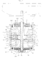
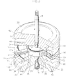
- FIGS. 2 and 3 are a sectional view and a partly cutaway perspective view for illustrating the hydraulic control unit part 2, respectively.
- the hydraulic control unit part 2 further comprises a first rotating member 18 which is connected to a lower end of the torsion bar 8 by a pin 16 to receive a rotation force of the steering wheel 10, second and third rotating members 20 and 22 which receive the rotation force from the first rotating member 18, and a fourth rotating member 24 which receives the rotation force from the second and third rotation members 20 and 22.
- the first rotating member 18 is integrally formed with a cylindrical sleeve 26 in which the torsion bar 8 is inserted.
- the torsion bar 8 is fixed to a lower end of the sleeve by the pin 16 and a lower end of which is supported to a cap 30 through a bearing 28.
- the first rotating member 18 includes grooves 34, 36, 38 and 40 formed on its flange 32, a hole 42 formed on its center through which the torsion bar 8 passes, pins 44 and 46 which project from its upper surface, and pins 78 and 80 projecting from its bottom surface.
- the second rotating member 20 has grooves 48 and 50 formed on its bottom surface to receive the pins 44 and 46, and vertical passages 52, 54, 56 and 58.
- the vertical passages 52, 54, 56 and 58 communicate with a channel 60 which is formed along an outer circumferential surface of the second rotating member 20 such that oil can flow therethrough. Further, a screw thread 62 is formed along the outer circumferential surface of the second rotating member 20 and a circumferential groove 64 is formed on the bottom surface of the second rotating member to receive ball members 118.
- the third rotating member 22, as shown in FIGS. 2, 3 and 6, includes a circumferential groove 66, aligned to the circumferential groove 64 of the second rotating member 20 and formed on its upper surface, a channel 68 formed along its outer circumferential surface, and vertical passages 70, 72, 74, and 76 communicating with the channel 68.
- the third rotating member 22 is provided with grooves 82 and 84 having a predetermined length to receive pins 78 and 80 which are formed on the bottom surface of the first rotating member 18.
- the fourth rotating member 24 includes upper horizontal passages 86, 88, 90 and 92 and lower horizontal passages 94, 96, 98 and 100 all of which can selectively communicate with the grooves 34, 36, 38 and 40 of the first rotating member.
- the upper horizontal passages 86, 88, 90 and 92 communicate with an oil pump(not shown) to receive the oil required for steering.
- the lower horizontal passages 94, 96, 98 and 100 are passages for returning the oil to a reservoir tank(not shown).
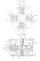
- the upper and lower horizontal passages are angularly offset from each other along the circumference when viewed from the plan view as shown in FIG. 9B. However, in a straight ahead position, each inner end of the upper and lower horizontal passages communicates with the grooves 34, 36, 38 and 40 of the first rotating member 18 such that the oil generated from the oil pump flows into the upper horizontal passages 86, 88, 90 and 92 and then flows out to the lower horizontal passages 94, 96, 98 and 100 via the grooves 34, 36, 38 and 40, respectively.
- the fourth rotating member 24 has vertical passages 102, 104, 106 and 108 which communicate with the vertical passages 52, 54, 56 and 58 of the second rotating member and the vertical passages 70, 72, 74 and 76 of the third rotating member.
- Pins 110 and 112 are formed on an upper surface of the fourth rotating member 24 and are located in grooves 111 and 113 formed on a bottom surface of the second member, respectively. Further, pins 114 and 116 are formed on a bottom surface of the fourth rotating member and are located in grooves 115 and 117 formed on an upper surface of the third rotating member, respectively.
- Ball members 118 are provided between the faces of the first, second, third and fourth rotating members 18, 20, 22 and 24 to aid smooth rotation.
- a screw thread 120 is formed on an outer circumferential surface of the third rotating member 22.
- the lower cap 30 is screw coupled to the lower portion of the cylinder 122.
- An upper cap 124 is also coupled to the upper portion of the cylinder 122.
- the first, second, third and fourth rotation members are disposed between the upper and lower caps 30 and 124 and the second and third rotating members are screw coupled to an inner circumferential surface of the cylinder 122.
- the cylinder 122 is provided with holes 126 and 128 formed on its one side and holes 130 and 132 which communicate with the channel 60 of the second rotating member and the channel 68 of the third rotating member, respectively.
- channels 133 and 134 are formed along the outer circumferential surfaces of the upper and lower horizontal passages of the fourth rotating member 24.
- FIG. 8 is a side sectional view for illustrating a power cylinder 4 of the present invention.
- the power cylinder includes a housing 136.
- the housing 136 is provided with intake ports 138 and 140 connected with fluid tubes 6a and 6b, respectively, and exhaust ports 142 and 144 opposite to intake ports 138 and 140, respectively.
- Check valves 146 and 148 are mounted between the ports 138 and 142 and the ports 140 and 144, respectively, to supply the oil to the chambers 150 and 152 or exhaust the oil from the chambers 150 and 152.
- a piston 154 is mounted in the housing 136 such that when the oil flows into one of the chambers 150 and 152, the piston 154 can move in a direction.
- a rack gear 156 is integrally formed on the piston and in mesh with a sector gear 158 coupled with the pitman arm 12.
- the grooves 34, 36, 38 and 40 of the first rotating member 18 are disposed to communicate with the upper and lower horizontal passages of the fourth rotating member 24.
- the oil transmitted from the oil pump during the engine operation flows into the hole 126 of the cylinder 122 and then is supplied to the channel 133 of the fourth rotating member 24 thereby flowing along the upper horizontal passages 86, 88, 90 and 92.
- the oil flows into the grooves 34, 36, 38 and 40 of the first rotating member 18 and, at this point, since the grooves 34, 36, 38 and 40 communicate with the lower horizontal passages 94, 96, 98 and 100, the oil returns to the reserver tank through the holes 128 of the cylinder 122.
- the pins 44 and 46 fixed on the first rotating member 18 are to be located in the grooves 48 and 50 of the second rotating member 20 and are designed to rotate the second rotating member 20 in the clockwise direction if the first rotating member rotates in the clockwise direction.
- the pins 78 and 80 fixed on the bottom surface of the first rotating member 18 and located in the grooves 82 and 84 of the third rotating member 22, respectively, are designed to rotate the third rotating member in the counter-clockwise direction if the first rotating member 18 rotates in the counter-clockwise direction.
- first, second and fourth rotating members 18, 20 and 24 rotate simultaneously such that the grooves 115 and 117 of the third rotating member 22 contact the pins 114 and 116, respectively, to rotate with the first, second and fourth rotating members 18, 20 and 24.
- the second and third rotating members 20 and 22 which are screw coupled to the cylinder 122 rotates along the screw thread of the cylinder to move upward, thereby providing a steering sensitivity.
- the springs 202 and 204 elastically supporting the second and third rotating member respectively absorb the movement of the rotating members.
- the second rotating member 20 is more rotated in the steering direction of the steering wheel than the third rotating member 22, such that the vertical passages 102, 104, 106 and 108 become in communication with the passages 52, 54, 56 and 58 of the second rotating member 20 (See FIGS. 10A and 10B).
- the hydraulic pressure supplied from the oil pump flows into the cylinder 122 through the hole 130 and then flows into the left chamber 150 of the power cylinder 4 along the fluid tube 6a via the vertical passages of the fourth rotating member 24 and the vertical passages of the second rotating member 20
- the steering system of the present invention since the steering of the vehicle is accomplished without steering shaft, a space for the driver can be enlarged.
Landscapes
- Engineering & Computer Science (AREA)
- Chemical & Material Sciences (AREA)
- Combustion & Propulsion (AREA)
- Transportation (AREA)
- Mechanical Engineering (AREA)
- Power Steering Mechanism (AREA)
Claims (12)
- Système de direction assistée pour véhicule comprenant :un organe de commande hydraulique (2) comprenant :un premier élément rotatif (18) tournant en réponse à une commande de direction du volant (10), ledit premier élément rotatif (18) comportant une pluralité de gorges (34, 36, 38, 40) réparties le long de sa circonférence extérieure ;un deuxième élément rotatif (20) disposé de manière coaxiale sur une partie supérieure du premier élément rotatif (18) pour recevoir la force de rotation dudit premier élément rotatif (18), ledit deuxième élément rotatif (20) étant muni d'un canal (60) disposé le long de sa circonférence extérieure ;un troisième élément rotatif (22) disposé de manière coaxiale sur une partie inférieure dudit premier élément rotatif (18) pour recevoir la force de rotation dudit premier élément rotatif (18), ledit troisième élément rotatif (22) étant muni d'un canal (68) disposé le long de sa circonférence extérieure ;un quatrième élément rotatif (24) disposé sur une circonférence extérieure dudit premier élément rotatif (18) entre lesdits deuxième et troisième éléments rotatifs (20, 22) pour recevoir la force de rotation provenant soit dudit deuxième élément rotatif soit dudit troisième élément rotatif (20, 22) et qui est destiné à alimenter en huile l'un des premier, deuxième et troisième éléments rotatifs (18, 20, 22) en réponse à un une commande de sens de rotation et à une valeur de rotation desdits deuxième et troisième éléments rotatifs (20, 22) ; etun cylindre destiné à recevoir lesdits premier, deuxième, troisième et quatrième éléments rotatifs (18, 20, 22, 24), ledit cylindre (122) comportant deux trous (130, 132) qui communiquent respectivement avec l'un des canaux de chacun des deuxième et troisième éléments rotatifs (20, 22) ; etun cylindre de commande (4) destiné à orienter des roues orientables vers la droite ou vers la gauche en déplaçant un piston (154) qui est relié aux roues orientables par une tige de traction (14) et un levier de direction (12), ledit cylindre de commande (4) étant relié audit organe de commande hydraulique (2) par deux tubes de commande hydraulique (6a, 6b) et le mouvement du piston (154) étant commandé par la pression hydraulique fournie par lesdits tubes de commande hydraulique (6a, 6b).
- Système de direction assistée selon la revendication 1, caractérisé en ce qu'une barre de torsion (8) est insérée dans un axe central (26) dudit premier élément rotatif (18) et est fixée à lui de façon à ce que ledit premier élément rotatif (18) reçoit une force de rotation provenant de ladite barre de torsion (8) ; et en ce que lesdits premier et deuxième éléments rotatifs (20, 22) sont disposés autour de ladite barre de torsion (8).
- Système de direction assistée selon la revendication 2, caractérisé en ce que ledit premier élément rotatif (18) comporte un manchon (26) qui sert d'axe central relié à ladite barre de torsion (8).
- Système de direction assistée selon la revendication 1, 2 ou 3, caractérisé en ce que ledit quatrième élément rotatif (24) a une pluralité de passages horizontaux supérieurs et inférieurs (86, 88, 90, 92 ; 94, 96, 98, 100) qui communiquent de manière sélective avec lesdites gorges (34, 36, 38, 40) dudit premier élément rotatif (18) et une pluralité de passages verticaux (102, 104, 106, 108) qui communiquent avec lesdits canaux (60, 68) desdits deuxième et troisième éléments rotatifs (20, 22).
- Système de direction assistée selon la revendication 4, caractérisé en ce que lesdits passages horizontaux supérieurs (86, 88, 90, 92) sont indexés angulairement par rapport aux dits passages horizontaux inférieurs (94, 96, 98, 100).
- Système de direction assistée selon la revendication 4 ou 5, caractérisé en ce que ledit quatrième élément rotatif (24) comprend un canal (133) qui est destiné à recevoir la pression hydraulique fournie par une pompe à huile et qui communique avec lesdits passages horizontaux (86, 88, 90, 92).
- Système de direction assistée selon la revendication 4, 5 ou 6, caractérisé en ce que lesdits deuxième et troisième éléments rotatifs (20, 22) comportent respectivement une pluralité de passages verticaux (52, 54, 56, 58 ; 70, 72, 74, 76) qui communiquent de manière sélective avec les passages verticaux (102, 104, 106, 108) dudit quatrième élément rotatif (24) en réponse à une commande de direction du véhicule.
- Système de direction assistée selon l'une quelconque des revendications 4 à 7, caractérisé en ce que les dites gorges (34, 36, 38, 40) dudit premier élément rotatif (18) communiquent avec les deux passages horizontaux supérieurs et inférieurs (86, 88, 90, 92 ; 94, 96, 98, 100) dudit quatrième élément rotatif (24) ; et en ce que lesdites gorges (34, 36, 38, 40) dudit premier élément rotatif (18) communiquent de manière sélective avec les passages horizontaux supérieurs ou inférieurs (86, 88, 90, 92 ; 94, 96, 98, 100) dudit quatrième élément rotatif (24) lorsque le véhicule tourne vers la gauche ou vers la droite.
- Système de direction assistée selon l'une quelconque des revendications précédentes, caractérisé en ce que ledit cylindre de commande (4) est muni d'orifices d'admission et d'évacuation (138, 140 ; 142, 144) et en ce qu'une soupape de retenue (146, 148) est montée entre les orifices d'admission et d'évacuation (138, 140 ; 142, 144).
- Système de direction assistée selon la revendication 9, caractérisé en ce que le cylindre de commande (4) est muni de premier et deuxième orifices d'admission (138, 140) tels que la pression hydraulique alimente de manière sélective une parmi deux chambres (150, 152) en ouvrant un desdits orifices d'admission (38, 40) ainsi qu'un piston (154) qui sépare lesdites chambres (150, 152) et qui est engrené dans un secteur denté (158) relié audit levier de direction (12).
- Système de direction assistée selon l'une quelconque des revendications précédentes, caractérisé en ce que ledit deuxième élément rotatif (20) reçoit la force de rotation par l'intermédiaire d'une goupille (44, 46) qui est fixée sur une surface supérieure dudit premier élément rotatif (18) et en ce que ledit troisième élément rotatif (22) reçoit la force de rotation par l'intermédiaire d'une goupille (78, 80) sur une surface inférieure dudit premier élément rotatif (18) ; chaque goupille (44, 46, 78, 80) étant logée dans des gorges (48, 50 ; 82, 84) qui sont respectivement formées sur une surface inférieure dudit deuxième élément rotatif (20) et sur une surface supérieure dudit troisième élément rotatif (24).
- Système de direction assistée selon l'une quelconque des revendications précédentes caractérisé en ce que des billes sont disposées sur chaque surface de contact séparant ledit premier élément rotatif (18) et lesdits deuxième et troisième éléments rotatifs (20, 22).
Applications Claiming Priority (1)
| Application Number | Priority Date | Filing Date | Title |
|---|---|---|---|
| PCT/KR1994/000131 WO1996010512A1 (fr) | 1994-09-30 | 1994-09-30 | Systeme de direction assistee pour vehicule |
Publications (2)
| Publication Number | Publication Date |
|---|---|
| EP0730541A1 EP0730541A1 (fr) | 1996-09-11 |
| EP0730541B1 true EP0730541B1 (fr) | 1999-03-17 |
Family
ID=19375312
Family Applications (1)
| Application Number | Title | Priority Date | Filing Date |
|---|---|---|---|
| EP94929031A Expired - Lifetime EP0730541B1 (fr) | 1994-09-30 | 1994-09-30 | Systeme de direction assistee pour vehicule |
Country Status (5)
| Country | Link |
|---|---|
| US (1) | US5769178A (fr) |
| EP (1) | EP0730541B1 (fr) |
| JP (1) | JP2894574B2 (fr) |
| DE (1) | DE69417254T2 (fr) |
| WO (1) | WO1996010512A1 (fr) |
Families Citing this family (4)
| Publication number | Priority date | Publication date | Assignee | Title |
|---|---|---|---|---|
| DE19823528A1 (de) * | 1998-04-17 | 1999-10-21 | Still Gmbh | Lenkbetätigungsvorrichtung |
| US7330050B2 (en) * | 2004-11-08 | 2008-02-12 | Tabula, Inc. | Storage elements for a configurable IC and method and apparatus for accessing data stored in the storage elements |
| JP6926835B2 (ja) * | 2017-08-30 | 2021-08-25 | いすゞ自動車株式会社 | ステアリング装置 |
| CN118182626B (zh) * | 2022-12-12 | 2025-12-16 | 比亚迪股份有限公司 | 车辆的转向机构以及车辆 |
Citations (1)
| Publication number | Priority date | Publication date | Assignee | Title |
|---|---|---|---|---|
| US3452543A (en) * | 1967-11-06 | 1969-07-01 | Trw Inc | Hydrostatic device |
Family Cites Families (9)
| Publication number | Priority date | Publication date | Assignee | Title |
|---|---|---|---|---|
| DE1944130A1 (de) * | 1968-09-11 | 1971-04-29 | Massey Ferguson Services Nv | Hydraulisches Steuersystem |
| US3724585A (en) * | 1971-04-15 | 1973-04-03 | Clark Equipment Co | Fluid steering system |
| US3991846A (en) * | 1975-08-07 | 1976-11-16 | Clark Equipment Company | Power steering system |
| US4300594A (en) * | 1978-07-27 | 1981-11-17 | Bendiberica S.A. | Hydraulic rotary distributor, particularly for power steering mechanisms |
| DE2856606C2 (de) * | 1978-12-29 | 1986-04-24 | Zahnradfabrik Friedrichshafen Ag, 7990 Friedrichshafen | Drehschieberlenkventil für Hilfskraftlenkungen |
| US4798256A (en) * | 1986-11-08 | 1989-01-17 | Zahnradfabrik Friedrichshafen, Ag. | Hydrostatic auxiliary steering device |
| DE4036589A1 (de) * | 1989-11-21 | 1991-05-23 | Zahnradfabrik Friedrichshafen | Zylinder-kolben-einheit |
| US5048630A (en) * | 1990-04-09 | 1991-09-17 | Ford Motor Company | Power steering trim control system |
| DE4217258A1 (de) * | 1992-05-25 | 1992-12-10 | Zahnradfabrik Friedrichshafen | Drehschieberventil fuer hydraulische hilfskraftlenkungen von kraftfahrzeugen |
-
1994
- 1994-09-30 JP JP8511629A patent/JP2894574B2/ja not_active Expired - Fee Related
- 1994-09-30 EP EP94929031A patent/EP0730541B1/fr not_active Expired - Lifetime
- 1994-09-30 US US08/632,467 patent/US5769178A/en not_active Expired - Fee Related
- 1994-09-30 DE DE69417254T patent/DE69417254T2/de not_active Expired - Fee Related
- 1994-09-30 WO PCT/KR1994/000131 patent/WO1996010512A1/fr not_active Ceased
Patent Citations (1)
| Publication number | Priority date | Publication date | Assignee | Title |
|---|---|---|---|---|
| US3452543A (en) * | 1967-11-06 | 1969-07-01 | Trw Inc | Hydrostatic device |
Also Published As
| Publication number | Publication date |
|---|---|
| US5769178A (en) | 1998-06-23 |
| DE69417254T2 (de) | 1999-11-04 |
| EP0730541A1 (fr) | 1996-09-11 |
| JP2894574B2 (ja) | 1999-05-24 |
| JPH09507808A (ja) | 1997-08-12 |
| DE69417254D1 (de) | 1999-04-22 |
| WO1996010512A1 (fr) | 1996-04-11 |
Similar Documents
| Publication | Publication Date | Title |
|---|---|---|
| KR890005322B1 (ko) | 후륜조타장치 | |
| JPH0241470B2 (fr) | ||
| US4586581A (en) | Vehicle control system | |
| GB1598848A (en) | Power-assisted steering system for motor vehicles | |
| EP0269088B1 (fr) | Système de direction sur les quatre roues pour véhicules à roues | |
| US4799514A (en) | Rotary servovalve for power-assisted steering system | |
| EP0263414B1 (fr) | Système de direction des 4 roues pour automobile | |
| US4821830A (en) | Automotive four wheel steering system | |
| US5769178A (en) | Power steering system for vehicle | |
| KR0135019B1 (ko) | 자동차용 조향핸들의 파워스티어링장치 | |
| JPH0657532B2 (ja) | 油圧動力補助操舵装置の自動直進復帰装置 | |
| JPH07117694A (ja) | パワーステアリング装置 | |
| US20090000855A1 (en) | Power steering device | |
| US4781261A (en) | Four-wheel steering system for automotive vehicles | |
| JPS61196875A (ja) | 4輪操舵装置 | |
| US5131486A (en) | Power steering control valve mechanism | |
| JPS6355472B2 (fr) | ||
| US5651424A (en) | Servo-assisted rack-and-pinion steering system | |
| US6253657B1 (en) | Steering apparatus | |
| JPH10264835A (ja) | 油圧パワーステアリング装置 | |
| JPH0698937B2 (ja) | 後輪操舵装置 | |
| JPH0692249A (ja) | 動力舵取装置 | |
| JPH0645419Y2 (ja) | 油圧装置の流量制御機構 | |
| JP3753568B2 (ja) | 動力舵取り装置のパワーシリンダ | |
| JPS59134064A (ja) | パワ−ステアリングのロ−タリ型作動弁装置 |
Legal Events
| Date | Code | Title | Description |
|---|---|---|---|
| PUAI | Public reference made under article 153(3) epc to a published international application that has entered the european phase |
Free format text: ORIGINAL CODE: 0009012 |
|
| 17P | Request for examination filed |
Effective date: 19960412 |
|
| AK | Designated contracting states |
Kind code of ref document: A1 Designated state(s): DE FR GB |
|
| 17Q | First examination report despatched |
Effective date: 19970506 |
|
| GRAG | Despatch of communication of intention to grant |
Free format text: ORIGINAL CODE: EPIDOS AGRA |
|
| GRAG | Despatch of communication of intention to grant |
Free format text: ORIGINAL CODE: EPIDOS AGRA |
|
| GRAH | Despatch of communication of intention to grant a patent |
Free format text: ORIGINAL CODE: EPIDOS IGRA |
|
| GRAH | Despatch of communication of intention to grant a patent |
Free format text: ORIGINAL CODE: EPIDOS IGRA |
|
| GRAA | (expected) grant |
Free format text: ORIGINAL CODE: 0009210 |
|
| AK | Designated contracting states |
Kind code of ref document: B1 Designated state(s): DE FR GB |
|
| REF | Corresponds to: |
Ref document number: 69417254 Country of ref document: DE Date of ref document: 19990422 |
|
| ET | Fr: translation filed | ||
| PLBE | No opposition filed within time limit |
Free format text: ORIGINAL CODE: 0009261 |
|
| STAA | Information on the status of an ep patent application or granted ep patent |
Free format text: STATUS: NO OPPOSITION FILED WITHIN TIME LIMIT |
|
| 26N | No opposition filed | ||
| PGFP | Annual fee paid to national office [announced via postgrant information from national office to epo] |
Ref country code: GB Payment date: 20001115 Year of fee payment: 7 |
|
| PGFP | Annual fee paid to national office [announced via postgrant information from national office to epo] |
Ref country code: FR Payment date: 20001128 Year of fee payment: 7 |
|
| PG25 | Lapsed in a contracting state [announced via postgrant information from national office to epo] |
Ref country code: GB Free format text: LAPSE BECAUSE OF NON-PAYMENT OF DUE FEES Effective date: 20010930 |
|
| REG | Reference to a national code |
Ref country code: GB Ref legal event code: IF02 |
|
| GBPC | Gb: european patent ceased through non-payment of renewal fee |
Effective date: 20010930 |
|
| PG25 | Lapsed in a contracting state [announced via postgrant information from national office to epo] |
Ref country code: FR Free format text: LAPSE BECAUSE OF NON-PAYMENT OF DUE FEES Effective date: 20020531 |
|
| REG | Reference to a national code |
Ref country code: FR Ref legal event code: ST |
|
| PGFP | Annual fee paid to national office [announced via postgrant information from national office to epo] |
Ref country code: DE Payment date: 20060928 Year of fee payment: 13 |
|
| PG25 | Lapsed in a contracting state [announced via postgrant information from national office to epo] |
Ref country code: DE Free format text: LAPSE BECAUSE OF NON-PAYMENT OF DUE FEES Effective date: 20080401 |