EP0730698B1 - Dichtungsanordnung für fenster, besonders dachfenster - Google Patents
Dichtungsanordnung für fenster, besonders dachfenster Download PDFInfo
- Publication number
- EP0730698B1 EP0730698B1 EP93907806A EP93907806A EP0730698B1 EP 0730698 B1 EP0730698 B1 EP 0730698B1 EP 93907806 A EP93907806 A EP 93907806A EP 93907806 A EP93907806 A EP 93907806A EP 0730698 B1 EP0730698 B1 EP 0730698B1
- Authority
- EP
- European Patent Office
- Prior art keywords
- flashing
- flange
- frame
- elements
- window frame
- Prior art date
- Legal status (The legal status is an assumption and is not a legal conclusion. Google has not performed a legal analysis and makes no representation as to the accuracy of the status listed.)
- Expired - Lifetime
Links
- 238000007789 sealing Methods 0.000 title claims abstract description 28
- 239000000463 material Substances 0.000 claims abstract description 17
- 238000001746 injection moulding Methods 0.000 claims abstract description 4
- 238000003466 welding Methods 0.000 claims abstract description 4
- 229920001971 elastomer Polymers 0.000 claims abstract description 3
- 229920002725 thermoplastic elastomer Polymers 0.000 claims abstract description 3
- 230000008878 coupling Effects 0.000 claims description 29
- 238000010168 coupling process Methods 0.000 claims description 29
- 238000005859 coupling reaction Methods 0.000 claims description 29
- 238000009434 installation Methods 0.000 claims description 12
- 239000011324 bead Substances 0.000 claims description 5
- 239000011521 glass Substances 0.000 claims description 4
- 230000006835 compression Effects 0.000 claims 1
- 238000000748 compression moulding Methods 0.000 claims 1
- 230000001681 protective effect Effects 0.000 claims 1
- 239000004033 plastic Substances 0.000 description 5
- 229920003023 plastic Polymers 0.000 description 5
- XLYOFNOQVPJJNP-UHFFFAOYSA-N water Substances O XLYOFNOQVPJJNP-UHFFFAOYSA-N 0.000 description 5
- 238000005452 bending Methods 0.000 description 3
- 229910052751 metal Inorganic materials 0.000 description 3
- 239000002184 metal Substances 0.000 description 3
- 238000012856 packing Methods 0.000 description 3
- 238000004026 adhesive bonding Methods 0.000 description 2
- 238000001125 extrusion Methods 0.000 description 2
- RYGMFSIKBFXOCR-UHFFFAOYSA-N Copper Chemical compound [Cu] RYGMFSIKBFXOCR-UHFFFAOYSA-N 0.000 description 1
- HCHKCACWOHOZIP-UHFFFAOYSA-N Zinc Chemical compound [Zn] HCHKCACWOHOZIP-UHFFFAOYSA-N 0.000 description 1
- 229910052782 aluminium Inorganic materials 0.000 description 1
- XAGFODPZIPBFFR-UHFFFAOYSA-N aluminium Chemical compound [Al] XAGFODPZIPBFFR-UHFFFAOYSA-N 0.000 description 1
- 238000010276 construction Methods 0.000 description 1
- 229910052802 copper Inorganic materials 0.000 description 1
- 239000010949 copper Substances 0.000 description 1
- 230000003247 decreasing effect Effects 0.000 description 1
- 238000005304 joining Methods 0.000 description 1
- 239000011133 lead Substances 0.000 description 1
- 238000004519 manufacturing process Methods 0.000 description 1
- 238000000034 method Methods 0.000 description 1
- 230000035515 penetration Effects 0.000 description 1
- 230000000717 retained effect Effects 0.000 description 1
- 239000002023 wood Substances 0.000 description 1
- 229910052725 zinc Inorganic materials 0.000 description 1
- 239000011701 zinc Substances 0.000 description 1
Images


Classifications
-
- E—FIXED CONSTRUCTIONS
- E04—BUILDING
- E04D—ROOF COVERINGS; SKY-LIGHTS; GUTTERS; ROOF-WORKING TOOLS
- E04D13/00—Special arrangements or devices in connection with roof coverings; Protection against birds; Roof drainage ; Sky-lights
- E04D13/14—Junctions of roof sheathings to chimneys or other parts extending above the roof
- E04D13/147—Junctions of roof sheathings to chimneys or other parts extending above the roof specially adapted for inclined roofs
- E04D13/1473—Junctions of roof sheathings to chimneys or other parts extending above the roof specially adapted for inclined roofs specially adapted to the cross-section of the parts extending above the roof
- E04D13/1475—Junctions of roof sheathings to chimneys or other parts extending above the roof specially adapted for inclined roofs specially adapted to the cross-section of the parts extending above the roof wherein the parts extending above the roof have a generally rectangular cross-section
-
- E—FIXED CONSTRUCTIONS
- E04—BUILDING
- E04D—ROOF COVERINGS; SKY-LIGHTS; GUTTERS; ROOF-WORKING TOOLS
- E04D13/00—Special arrangements or devices in connection with roof coverings; Protection against birds; Roof drainage ; Sky-lights
- E04D13/03—Sky-lights; Domes; Ventilating sky-lights
- E04D13/0305—Supports or connecting means for sky-lights of flat or domed shape
- E04D13/031—Supports or connecting means for sky-lights of flat or domed shape characterised by a frame for connection to an inclined roof
Definitions
- the invention relates to a flashing arrangement for windows, in particular roof windows, with a mainly rectangular window frame comprising a top member, two side members, and a bottom member, comprising flashing elements attached to the frame members, said flashing elements being profiles of a flexible material for providing a waterproof flashing frame around the window frame, the flashing elements at the top and side members of the window frame having a U-shaped cross section comprising a bottom plane, which in its working position is substantially parallel to the glass section of the window, and two upwardly protruding side flanges, of which a first side flange is attached to the outside of the corresponding member of the window frame.
- a flashing arrangement of the above-mentioned kind is known incorporating a flashing collar providing a water discharge duct and connectable with an extension profile of metal, plastics or another rigid or slightly flexible material.
- special member is required to provide sealing towards the underside of the surrounding roofing and the arrangement is not adapted for easy connection with a standard flashing element such as a conventional lead skirt below the bottom member of the frame.
- a window can be delivered substantially ready for installation, such that an easier installation is achieved, which is particularly advantageous when several closely spaced windows are to be installed either side by or above each other.
- the latter design is limited in that it can only be used together with plastic frame structures and mainly plane types of roofing, such as slating and the like, since the sealing flange has not been designed to he deformable to such a degree that it may be placed in sealing abutment with a wave-shaped roofing, such as for instance roofing tiles.
- the sealing arrangement according to the invention is characterized in that the flashing elements at the top and side members of the window frame are made of an elastically deformable material and that the other of said two side flanges serves as a seal in sealing abutment with the underside of the surrounding roofing, while the flashing element at the bottom member includes a profile with a mainly L-shaped cross section with an upright flange for connection to the outside of the main frame bottom member and an outwardly protruding flange.
- a U-shaped channel is established along the top and side members of the main frame structure, said channel at the top member providing a valley from which water may be led around the frame structure and through the channels acting as drains along the side members, in order to finally be drained off across the sealing element connected to the bottom member.
- the elastic deformability of the flashing arrangements together with the U-shaped cross-sectional profile results in a particularly good fit to the surrounding roofing, in that the other side flange, which is separated from main frame structure, can be deformed for a sealing abutment with the underside of any common roofing, for instance by bending the side flange more or less outwards from the U-profile, possibly to such a degree that it is nearly flush with the bottom plane of the profile.
- the factory mounted flashing elements can easily be wrapped up over the main frame structure during packing and shipping, resulting in only a minimal increase of its outer dimensions.
- the L-shaped flashing element at the bottom member can be joined directly to the roofing by placing the protruding flange of the profile either under or in sealing abutment with the top side of the material underlying the roofing.
- the protruding flange of the L-shaped flashing element may be designed to be connected, for instance by gluing, to another flexible and plastically deformable flashing element, which may be of the above mentioned traditional type or of the unleaded design described in International Patent Application No. WO 93/06318 (published 01.04.93), and having improved deformability which will further contribute to facilitating the installation work.
- the invention makes it also possible in a simple manner, to establish sealing flashings between relatively closely spaced neighboring windows, for instance when the spacing is about 100 mm, corresponding to the normal width of a rafter, regardless of whether the windows are placed next to or above each other.
- a particularly well suited embodiment according to the invention is characterized in that a coupling flange is constructed on the top side of the bottom face of the U-profile at a relatively short distance from said first side flange, where said coupling flange extends towards said first side flange substantially in parallel to the bottom face, and during the installation of two windows side by side may be placed in abutment with the corresponding coupling flange of the neighboring window after having cut off the part of the flashing elements lying between said coupling flange and the other side flange along the mutually opposing side members of the window frame, after which the two coupling flanges are connected by a profiled sliding rail with bent flange sections fitting into the space between the two coupling flanges and the bottom faces of the respective flashing elements.
- the flashing element at the top member of the main frame on account of providing a valley preferably is designed with an increased width compared to the the flashing requirements at the side members, a similar building together of windows placed above each other may be obtained when the flashing element at the top member of the window frame in the middle section between said first and second side flange has an additional upwardly protruding flange, which during the installation of two windows above each other may be placed under the L-shaped flashing element at the bottom frame member of the above window after having cut off the part of the flashing element lying between said additional flange and the second side flange.
- the flashing frame according to the invention illustrated in Figure 1 is designed for mounting on the main frame structure of a skylight to be built into a roof with an inclined plane.
- this main frame structure which may be of a conventional design including a top member, two side members, and a bottom member, the sectional view in Figure 2 only shows one of the side members 1.
- the flashing frame which is designed with factory assembly in mind, comprises a flashing element 2 for attachment to the main frame top member, elements 3 and 4 for attachment to the main frame side members, and an element 5 for attachment to the main frame bottom member.
- the flashing elements 2, 3, and 4 have, as shown in Figure 2, an mainly U-shaped cross-sectional profile comprising a bottom face 6, which, when the frame is mounted on the window, essentially extends in parallel to the glass section 7 of the window, and two side flanges 8 and 9 protruding upwards from the bottom face 6.
- the flashing element 2 for mounting onto the top member of the frame preferably has a greater width than the elements 3 and 4 intended for mounting on the side members on account of its function as a valley, which will be described in the following.
- the first side flange 8 is designed for attachment to the outside of the window frame member 1, while the other side flange 9 being detached from the frame structure provides abutment with the underside of the surrounding not shown roofing.
- the flashing element 5 comprises an L-shaped profile corresponding to the part of the cross-section shown in Figure 2 lying to the left of the dashed line 10, i.e. with an upwardly protruding flange corresponding to the first side flange 8 intended for attachment to the main frame bottom member, and an outwardly protruding flange 11, which in the shown embodiment is designed for connection to another plastically deformable and mainly strip-shaped adjoining element 12.
- an additional element will normally not be necessary, since the outwardly protruding flange can be placed over the upper edge of the underlying roofing.
- the flashing elements 2-5 are according to the invention made of an elastically deformable material, preferably a material suitable for extrusion, as for instance rubber or a thermoplastic elastomer.
- the shown rectangular frame shape of the flashing may be produced by welding together appropriate lengths of extruded profile elements with the U-shaped and L-shaped cross sections described above, whereby corner sections at the inside of the side flanges designed for attachment to the main frame side members are cut away, such that the welded frame shown in Figure 1 provides an open channel around the window frame structure.
- This manufacturing method is advantageous since flashing frames of arbitrary sizes can be produced from a limited number of profile elements for mounting on the top member, side members and bottom member of a main frame structure, respectively,
- the flashing frame with the exception of the joining element 12 can be produced as an assembled unit, for instance by injection moulding.
- the flashing frame can be mounted on window frame structures of arbitrary materials, including wood, plastic and metal frame profiles. Attachment to the window frame structure can also be performed in a known manner, as for instance by glueing.
- the U-profiles attached to the top and side members of the main frame structure will provide a continuous channel around the window frame structure. Above the top member this channel functions as a valley for water drainage, while the channels along the main frame side members function as drains removing the water, which via the plastically derformable adjoining element below the main frame bottom member is led out across the roof section below the window.
- the side members of the main frame structure will be placed in close abutment with the underside of the surrounding roofing and provide an effective screen against water penetration.
- the detached side flange 9 provides a satisfactory screen against drifting snow.
- the fit to the surrounding roofing is provided mainly by bending the side flange 9 outwards, possibly to such a degree that it is nearly flush with the bottom face 6, which particularly will be the case with plane or flat roofings.
- roofings made of roof tiles or similar wave-shaped materials, which are laid upon laths a more or less upright form of the flange can be retained.
- the window frame structure is covered by a skirt 13, consisting of profile elements of metal or hard plastic.
- the flashing frame according to the invention can contribute to an improved seal, in that the side flange 8 attached to the side member 1 of the window frame at its upper section either can be designed with a sealing lip 14 in abutment with an overlying part of the window, for instance the window frame of an openable window, or, as shown in Figure 2, the glass section itself of a fixed window.
- the sealing lip 14 can be connected to the side flange 8 by a cover flange 15, which provides good protection of the outside of the frame member 1.
- an outwardly protruding sealing flange may be designed for sealing abutment with the inside of the skirt 13.
- the flashing frame according to the invention offers the possibility of providing an effectively sealing flashing in connection with closely spaced neighboring windows on a roof plane, for instance in the case of windows lying side by side, where the mutually opposing sides of the window frame are fastened to the same rafter, such that the space between these frame sides becomes less than the width of the rafter.
- the shape of the profile for the flashing elements intended for attachment to the side members of the window frame can be modified as shown in Figure 3, where a downwardly bent coupling flange 18 is constructed at the bottom section of the side of the side flange 17 facing the inside of the U-profile, and an upwardly protruding rib or bead 21 is constructed on the top side of the bottom face 19 of the profile at a relatively short distance from the other side flange 20.
- the profile elements With two closely spaced windows placed side by side the profile elements are cut off along the lines 22 and 23 as shown in Figure 3, such that the part of the profile in Figure 3, which lies to the left of the dashed line 22 and contains the coupling flange 18, is attached to one of the mutually opposing side members of the main frame, while the part of the profile in Figure 3 lying to the left of the dashed line 23 is attached to the other side member, and in addition to the coupling flange 18 contains the rib or bead 21.
- the thus mounted profiled flashing elements can then be joined together by allowing the rib or bead 21 of one of the profiles to be positioned under the coupling flange 18 of the other profile, thereby engaging said under coupling flange 18.
- the invention provides an opportunity for effective flashing between two windows relatively closely positioned above each other by bending down the detached upright flange 9 of the element attached to the main frame top member of the lower window, after which said detached upright flange 9 is bent down and overlapped with the plastically deformable adjoining element 12 below the bottom member of the window frame of the above window.
- the plastically deformable adjoining element 12 which serves as a shape-fitted connection to the top side of the material underlying the roofing, may consist of a conventional flashing plate containing lead or an unleaded flashing of the type described in aforementioned patent application No. PCT/DK92/0028/.
- the flashing elements 24 and 25 for attachment to the top member and two side members of the window frame structure, respectively, have, as in the embodiments shown in Figures 1-3, a mainly U-shaped cross-sectional profile with a bottom face 27, 28, respectively, and a first and second side flange, 29,39 and 31,32, respectively, protruding upwards from the inner and outer edges of the bottom face 27,28.
- the first side flange 29, 30 is designed for attachment to the outside of the corresponding side member 33 or top member 34 of the main frame, and in the same manner as shown in Figure 2 this side flange 29 may at the flashing elements 25 belonging to the side members of the window frame, see Figure 5, be designed with an outwardly protruding packing flange 35 for a sealing abutment with the inside of a skirt 36 covering the top side and the top part of the outside of the main frame side member 33.
- the top part of the first side flange 30 is at the flashing element 24 belonging to the main frame top member 34 in a similar manner covered by a covering rail 37, which extends across a the top side of the main frame top member.
- the detached second side flange 31,32 protrudes upwards from the bottom face 27,28 near the outer edge of said bottom face for the purpose of producing a sealing abutment with the underside of the surrounding roofing.
- the outermost part of the second side flange 31,32 is constructed with a decreasing thickness, such that it provides a kind of sealing lip with good elastic deformability.
- the detached side flange 31 is placed at such a distance from the first side flange 29 that the flashing element during packing and shipping by utilizing the elasticity of the material can be wrapped up around the window structure with the detached side flange 31 lying over the top side of the structure.
- the relatively small part of the edge section of the flashing element, which lies outside the detached side flange 31, can in this situation provide a certain additional protection of the frame structure of the window against mechanical damage.
- the flashing element 24 at the main frame top member 34 is designed with an increased width compared to the flashing elements 25 at the main frame side members for the purpose of providing a valley as explained previously.
- the mainly L-shaped flashing element 26 at the main frame bottom member 40 is in this embodiment, as shown in Figure 7, constructed with a catching flange 41 extending diagonally backwards and downwards on the bottom side at or near its free outer edge.
- the catching flange 41 encloses the edge of a spring rail 42, which is attached to the main frame bottom member 40 behind the attachment flange 43 of the flashing element 26 and is downwardly preloaded, such that the spring rail 42 during the utilization of the flashing arrangement in connection with a plane roofing, as for instance slating or cardboard, pulls the outer edge, likewise constructed as a sealing lip, into sealing abutment with the top side of the roofing.
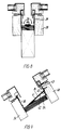
- FIGs 8 and 9 it is illustrated how the embodiment of the flashing arrangement shown in Figures 4-7 is employed in connection with the building together of two relatively closely spaced windows positioned either above or next to each other.
- a coupling flange 44 is constructed at the flashing element 25, said coupling flange 44 being positioned on the top side 27 of the bottom face of the U-profile at a relatively short distance from the attachment flange 29 while extending substantially in parallel to the bottom face 27 and towards the attachment flange 29.
- the coupling flanges are then connected by means of a sliding profiled rail 46 with flange sections that are bent around, gripping into the spaces between the two coupling flanges 44 and the bottom faces 27 of the flashing element 25.
- the flashing element 24 at the main frame top member 34 is designed with an additional upwardly protruding flange 47, as shown in Figure 6, in the middle area between the attachment flange 30 and the detached flange 32.
- the part lying outside the additional flange 47 is cut off from the flashing element 24, i.e. along the dashed line 48 in Figures 4 and 6, and the flashing element connected to the top member of the frame 34 can now be placed under the flashing element 26 connected to the bottom member of the frame of the above window, the additional flange 47 being in abutment with the main frame bottom member of the above window.
- the flashing arrangement in Figures 4-7 can be manufactured in the same manner as described in the above, i.e. by welding together appropriate lengths of extruded profile elements with the shown and described cross-sectional profiles in such a manner that the welded frame, as shown in Figure 4, provides an open channel around the window frame structure, or the arrangement can be produced as an assembled unit by injection moulding.
- the flashing arrangement is mounted on the main frame structure in the factory, and the complete window including the mounted flashing elements is delivered in an embodiment completely ready for installation, whereby the work of providing separate flashings of conventional materials is avoided.
- an additional element 49 may be delivered with the flashing arrangement, as shown in Figure 10.
- This element has a substantially U-shaped unfolded configuration, such that it comprises two relatively short side pieces 50 and 51, which after removal of the detached flanges 31 at the bottom part of the flashing elements 25 connected to the main frame side members may be placed under the bottom part of these flashing elements and the flashing element 26 connected to the main frame bottom member, which also in this case is pressed downwards when installing a spring rail, as shown in Figure 7.
- a flexible and plastically deformable adjoining element 52 of a known type is connected to the bottom edge of the additional element 48.
Landscapes
- Architecture (AREA)
- Civil Engineering (AREA)
- Structural Engineering (AREA)
- Engineering & Computer Science (AREA)
- Roof Covering Using Slabs Or Stiff Sheets (AREA)
- Seal Device For Vehicle (AREA)
- Specific Sealing Or Ventilating Devices For Doors And Windows (AREA)
- Building Environments (AREA)
- Door And Window Frames Mounted To Openings (AREA)
- Body Structure For Vehicles (AREA)
- Extrusion Moulding Of Plastics Or The Like (AREA)
- Building Awnings And Sunshades (AREA)
- Window Of Vehicle (AREA)
- Injection Moulding Of Plastics Or The Like (AREA)
Claims (14)
- Eindeckungsanordnung für Fenster, insbesondere Dachfenster mit einem im wesentlichen rechteckigen Blendrahmen, bestehend aus einem Oberteil (34), zwei Seitenteilen (1,33) und einem Unterteil (40), umfassend mit den Fensterteilen verbundene Eindeckungselemente (2-5, 24-26), welche im Hinblick auf Etablierung eines den Blendrahmen umgebenden wasserdichten Eindeckungsrahmens aus Profilen eines flexiblen Materials bestehen, wobei die Eindeckungselemente (2, 3, 4, 24, 25) an den Ober- und Seitenteilen des Blendrahmens einen U-förmigen Querschnitt haben und eine in der Betriebsstellung zu der Fensterverglasung (7) im wesentlichen parallele Bodenfläche (6;27-28) sowie zwei aufwärts hervorstehende Seitenflansche (8,9;29,31;30,32) umfassen, wobei der erste Seitenflansch (8,29, 30) mit der Aussenseite des entsprechenden Blendrahmenteils (1;33,34) verbunden ist, dadurch gekennzeichnet, dass die Eindeckungselemente (2,3, 4; 24, 25) an den Ober- und Seitenteilen des Blendrahmens aus einem elastisch verformbaren Material hergestellt sind, und dass der andere der erwähnten beiden Seitenflansche (9,31,32) als eine sich mit der umgebenden Dachdeckungsunterseite in abdichtender Anlage funktionierende Dichtung dient, während das Eindeckungselement (5, 26) des Unterteils (40) ein Profil eines im wesentlichen L-förmigen Querschnittes einschliesslich eines aufrechtstehenden Flansches (43) zur Verbindung mit der Aussenseite des Blendrahmenunterteils (40) und eines nach aussen hervorstehenden Flansches umfasst.
- Eindeckungsanordnung nach Anspruch 1, dadurch gekennzeichnet, dass der erste Seitenflansch (8) an dessen Oberseite mit einer Eindeckungskante (14) zur Anlage an die Unterseite des überliegenden Fensterteils (7) ausgebildet ist.
- Eindeckungsanordnung nach Anspruch 2, dadurch gekennzeichnet, dass die erwähnte Eindeckungskante (14) mittels eines an der Oberseite des Rahmenteils (1) angebrachten Abdeckungsflansches (15) mit dem ersten Seitenflansch (8) verbunden ist.
- Eindeckungsanordnung nach Anspruch 1, 2 oder 3, dadurch gekennzeichnet, dass am Oberteil des ersten Seitenflansches (8,25) zur Anlage an die Innenseite eines mit dem Rahmenteil (1) verbundenen äusseren Schutzelementes (13, 36) ein nach aussen hervorstehender Eindeckungsflansch (16, 35) ausgebildet ist.
- Eindeckungsanordnung nach einem der vorerwähnten Ansprüche, dadurch gekennzeichnet, dass ein abwärts gebogener Kupplungsflansch (18) am Unterteil der Seite des Seitenflansches (17) gegenüber der Innenseite des U-Profils ausgebildet ist, und dass an der Oberseite der Bodenfläche (19) in verhältnismässig kurzem Abstand vom anderen Seitenflansch (20) aufwärts hervorstehend eine Rippe bzw. ein Wulst (21) vorhanden ist, indem bei Verbindung der Eindeckungselemente zwei gegenüberliegender Rahmenteile eng benachbarter Fenster, nach dem Abschneiden eines Teils der mit den Blendrahmenteilen verbundenen Eindeckungselemente, die erwähnte Rippe bzw. der erwähnte Wulst unter diesem Kupplungsflansch angebracht werden kann, wodurch diese bzw. dieser unter dem erwähnten Kupplungsflansch (18) eingreift.
- Eindeckungsanordnung nach einem der Ansprüche 1-4, dadurch gekennzeichnet, dass auf der Oberseite der Bodenfläche (27) des U-Profils in verhältnismässig kurzem Abstand vom erwähnten ersten Seitenflansch (29) ein Kupplungsflansch (44) ausgebildet ist, welcher in Richtung gegen den ersten Seitenflansch im wesentlichen parallel zur Bodenfläche verläuft, so dass beim Einbau von zwei Fenstern nebeneinander, nach dem Abschneiden des sich zwischen dem erwähnten Kupplungsflansch (44) und dem zweiten Seitenflansch (31) entlang der gegenüberliegenden Seitenteile des Blendrahmens befindlichen Teils der Eindeckungselemente der erwähnte Kupplungsflansch zur Anlage an den entsprechenden Kupplungsflansch (44) des benachbarten Fensters angebracht werden kann, wonach die beiden Kupplungsflansche (44) mittels einer Gleitschiene (46) mit gebogenen in den Zwischenraum zwischen den beiden Kupplungsflanschen (44) und den Bodenflächen der jeweiligen Eindeckungselemente einpassenden Flanschverbindungen verbunden sind.
- Eindeckungsanordnung nach einem der vorerwähnten Ansprüche, dadurch gekennzeichnet, dass das Eindeckungselement (24) des Blendrahmenoberteils (34) im Hinblick auf Etablierung einer Kehle mit einer im Verhältnis zu den Eindeckungselementen (25) der Seitenteile des Blendrahmens grösseren Weite ausgebildet ist.
- Eindeckungsanordnung nach Anspruch 7, dadurch gekennzeichnet, dass die Eindeckungselemente (24) des Blendrahmenoberteils im Mittelbereich zwischen dem erwähnten ersten und zweiten Seitenflansch (30, 32) einen zusätzlichen aufwärts hervorstehenden Flansch (47) haben, welcher beim Einbau von zwei Fenstern übereinander nach dem Abschneiden des sich zwischen dem erwähnten zusätzlichen Flansch (47) und dem anderen Seitenflansch (32) befindlichen Teils des Eindeckungselementes unter das L-förmige Eindeckungselement (26) am Blendrahmenunterteil (40) des oberen Fensters angebracht werden kann.
- Eindeckungsanordnung nach einem der vorerwähnten Ansprüche für den Einsatz in Verbindung mit flachen und ebenen Dächern, dadurch gekennzeichnet, dass das im wesentlichen L-förmige Eindeckungselement (26) am Unterteil (40) des Blendrahmens an oder nahe dessen freier äusserer Bodenkante mit einem diagonal nach hinten verlaufenden Fangflansch (41) versehen ist, welcher derart ausgebildet ist, wenn mit dem Unterteil des Eindeckungselements (26) in Verbindung, eine mit dem Unterteil (40) des Blendrahmens verbundene Federschiene (42) zu umfassen, indem die Verbindung der erwähnten Federschiene (42) in Richtung des unterliegenden Daches erfolgt, um das Eindeckungselement (26) in abdichtender Anlage an die obere Dachseite zu halten.
- Eindeckungsanordnung nach einem der Ansprüche 1-8 für den Einsatz in Verbindung mit wellenförmigen Dächern, dadurch gekennzeichnet, dass zwecks Verbindung mit dem Eindeckunqselement (26) am Blendrahmenunterteil (40) ein zusätzliches, U-förmiges, ungefaltetes Element (49) ausgebildet ist, indem das zusätzliche Element (49) zwei verhältnismässig kurze Seitenstücke (50,51) umfasst, welche unter dem niedrigen Teil des Eindeckungselements (25) der Seitenteile (33) des Blendrahmens angebracht werden können, und wobei das zusätzliche Element (49) an dessen äusseren Kante mit noch einem weiteren flexiblen und plastisch verformbaren angrenzenden Element verbunden ist.
- Eindeckungsanordnung nach einem der vorerwähnten Ansprüche, dadurch gekennzeichnet, dass die Eindeckungselemente (2-4; 24-26) aus Gummi sind.
- Eindeckungsanordnung nach einem der Ansprüche 1-10, dadurch gekennzeichnet, dass die Eindeckungselemente (2-4; 24-26) aus einem thermoplastischen Elastomer sind.
- Eindeckungsanordnung nach Anspruch 11, dadurch gekennzeichnet, dass die Eindeckungselemente (2-4; 24-26) als extrudierte Profile hergestellt sind, welche zwecks Ausbildung eines Eindeckungsrahmens durch Schweißen zusammengefügt werden können.
- Eindeckungsanordnung nach Anspruch 12, dadurch gekennzeichnet, dass sie durch Pressen oder Spritzgießen als ein Eindeckungsrahmen aus einem einzelnen Stück hergestellt ist.
Applications Claiming Priority (3)
| Application Number | Priority Date | Filing Date | Title |
|---|---|---|---|
| DK827/92 | 1992-06-23 | ||
| DK92827A DK82792D0 (da) | 1992-06-23 | 1992-06-23 | Inddaekning til vinduer, navnlig tagvinduer |
| PCT/DK1993/000061 WO1994000655A1 (en) | 1992-06-23 | 1993-02-22 | A sealing arrangement for windows, in particular roof windows |
Publications (2)
| Publication Number | Publication Date |
|---|---|
| EP0730698A1 EP0730698A1 (de) | 1996-09-11 |
| EP0730698B1 true EP0730698B1 (de) | 1997-10-01 |
Family
ID=8097999
Family Applications (1)
| Application Number | Title | Priority Date | Filing Date |
|---|---|---|---|
| EP93907806A Expired - Lifetime EP0730698B1 (de) | 1992-06-23 | 1993-02-22 | Dichtungsanordnung für fenster, besonders dachfenster |
Country Status (16)
| Country | Link |
|---|---|
| US (1) | US6212834B1 (de) |
| EP (1) | EP0730698B1 (de) |
| JP (1) | JP3444600B2 (de) |
| AT (1) | ATE158834T1 (de) |
| AU (1) | AU665076B2 (de) |
| CA (1) | CA2136314C (de) |
| CZ (1) | CZ286888B6 (de) |
| DE (1) | DE69314357T2 (de) |
| DK (1) | DK82792D0 (de) |
| ES (1) | ES2108868T3 (de) |
| HU (1) | HU216428B (de) |
| PL (1) | PL185177B1 (de) |
| RU (1) | RU2103468C1 (de) |
| SK (1) | SK280175B6 (de) |
| UA (1) | UA26350C2 (de) |
| WO (1) | WO1994000655A1 (de) |
Cited By (4)
| Publication number | Priority date | Publication date | Assignee | Title |
|---|---|---|---|---|
| CN104196130A (zh) * | 2014-09-04 | 2014-12-10 | 江苏正方园建设集团有限公司 | 一种水景玻璃采光天棚的防水结构及其制备方法 |
| DK202270175A1 (en) * | 2022-03-31 | 2024-02-09 | Vkr Holding As | A roof window and a method of mounting a bottom flashing member |
| USD1052757S1 (en) | 2023-03-30 | 2024-11-26 | Vkr Holding A/S | Window |
| USD1065597S1 (en) | 2023-03-30 | 2025-03-04 | Vkr Holding A/S | Window component |
Families Citing this family (37)
| Publication number | Priority date | Publication date | Assignee | Title |
|---|---|---|---|---|
| JPH05256293A (ja) * | 1992-03-12 | 1993-10-05 | Fujitsu General Ltd | 空気調和機の制御装置 |
| AU712432B2 (en) * | 1992-06-25 | 1999-11-04 | Regent Sheet Metal Pty Ltd | Improved roof aperture flashing assembly |
| AU686419B2 (en) * | 1994-09-06 | 1998-02-05 | Regent Sheet Metal Pty Ltd | Improved roof aperture flashing assembly |
| US5675940A (en) * | 1996-10-15 | 1997-10-14 | Bahar; Reuben | Skylight leakage barrier |
| NL1008048C2 (nl) * | 1998-01-16 | 1999-07-19 | Ubbink Nederland Bv | Verholen goot. |
| DK199900873A (da) | 1999-06-18 | 2001-04-02 | Vkr Holding As | Isoleringsramme for et ovenlysvindue |
| ES2208566T3 (es) * | 2000-02-29 | 2004-06-16 | Vkr Holding A/S | Material de tapajuntas para tejados en forma de placa laminada. |
| US6354046B1 (en) * | 2000-07-29 | 2002-03-12 | Michael R Swearingen | Skylight membrane with diverter |
| ES2334332T3 (es) * | 2000-11-25 | 2010-03-09 | Vkr Holding A/S | Tapajuntas de tejado regulable y kit de tapajuntas. |
| US6804918B2 (en) | 2001-01-19 | 2004-10-19 | Vkr Holding A/S | Roof window assembly comprising a window component and an external screening accessory |
| GB2388399B (en) * | 2001-01-19 | 2004-10-06 | Vkr Holding As | A roof window assembly and components |
| EP1521888B1 (de) * | 2002-07-17 | 2010-11-24 | VKR Holding A/S | Dichtungsstreifen und dichtungsset |
| US20050034385A1 (en) | 2003-07-15 | 2005-02-17 | Broad Robert Patrick | Window sill flashing |
| US7168211B2 (en) * | 2003-09-02 | 2007-01-30 | Solatube International, Inc. | Tubular skylight with dome flashing and protective waffle pattern corrugation |
| US7040061B2 (en) * | 2003-09-02 | 2006-05-09 | Solatube International, Inc. | Tubular skylight with dome flashing and protective corrugation |
| US7386958B2 (en) * | 2003-10-14 | 2008-06-17 | Vkr Holding A/S | Pre-manufactured self-flashed curb assembly for rooftop daylighting systems |
| US7222462B2 (en) * | 2003-12-17 | 2007-05-29 | Astro Plastics, Inc. | Sill pan system |
| EP1584769A1 (de) * | 2004-04-08 | 2005-10-12 | Ubbink B.V. | Dachfenster |
| US20050268559A1 (en) * | 2004-05-21 | 2005-12-08 | Ellingson Robert T | Rollable door seal with integral intumescent strips |
| US20060199527A1 (en) * | 2005-02-04 | 2006-09-07 | Ruxton Products,Llc | Attic vent |
| GB2439319A (en) * | 2006-06-22 | 2007-12-27 | Metal Window Co Ltd | Rooflight comprising a water deflector |
| US8261498B2 (en) * | 2008-06-19 | 2012-09-11 | Tremco Incorporated | Modified glazing assembly for rough openings |
| USD714969S1 (en) | 2012-08-10 | 2014-10-07 | Norwood Architecture, Inc. | Window flashing product |
| US8959842B2 (en) | 2012-08-10 | 2015-02-24 | Norwood Architecture, Inc. | Prefabricated flashing product |
| US9745790B2 (en) | 2012-08-10 | 2017-08-29 | Norwood Architecture, Inc. | Prefabricated flashing product |
| US9745789B2 (en) | 2012-08-10 | 2017-08-29 | Norwood Architecture, Inc. | Prefabricated flashing product |
| GB2510326B (en) * | 2012-11-22 | 2015-07-01 | Forticrete Ltd | Roof drainage system |
| DK177601B1 (en) * | 2013-01-07 | 2013-11-18 | Vkr Holding As | A gutter-like flashing member and a roof structure including such a flashing member |
| USD750804S1 (en) * | 2013-08-30 | 2016-03-01 | Vkr Holding A/S | Connector element for use in a flashing assembly for roof windows |
| US9540818B2 (en) * | 2014-03-24 | 2017-01-10 | Bluescope Buildings North America, Inc. | Roof ridge integrated water-shedding apparatus |
| US10161179B2 (en) | 2015-11-13 | 2018-12-25 | Norwood Architecture, Inc. | Three-dimensional prefabricated flashing scaffolding system |
| WO2018209424A1 (en) * | 2017-05-15 | 2018-11-22 | Antoine Bourque | Roof vent with integrated shield |
| US11592197B2 (en) | 2018-09-28 | 2023-02-28 | Solatube International, Inc. | Bottom-mounted whole house fan assembly |
| USD957003S1 (en) | 2019-09-25 | 2022-07-05 | Vkr Holding A/S | Window accessory |
| DK181083B1 (en) * | 2020-12-30 | 2022-12-06 | Vkr Holding As | A roof window system with an improved stabilizing assembly |
| DK181500B1 (en) * | 2020-12-30 | 2024-03-12 | Vkr Holding As | A roof window system with a cover assembly |
| DK181645B1 (en) * | 2023-02-17 | 2024-08-23 | Vkr Holding As | A packed flashing assembly for use with a group of roof windows and a method for weatherproofing a group of roof windows |
Family Cites Families (9)
| Publication number | Priority date | Publication date | Assignee | Title |
|---|---|---|---|---|
| US3921352A (en) * | 1973-09-04 | 1975-11-25 | E J Products Corp | Glazing system |
| AT352980B (de) * | 1975-11-28 | 1979-10-25 | Prix Helmut | Einrichtung zur einfassung einer dachdurch- dringung, z.b. eines kamins oder eines dach- fensters, und zum anschluss der einfassung an eine profilierte dachhaut |
| FR2449176A1 (fr) * | 1979-02-15 | 1980-09-12 | Wiedemann Yvan | Entourage de souche de cheminee |
| DE2929604C2 (de) * | 1979-07-21 | 1986-01-23 | Blefa GmbH, 5910 Kreuztal | Einfassung für in der Dachfläche liegende Dachfenster, Sonnenkollektoren oder dgl. |
| GB2132247B (en) * | 1982-12-14 | 1986-09-10 | Charles Frederick Pritchard | Roof and wall seal assemblies |
| US4527368A (en) * | 1982-12-27 | 1985-07-09 | Wasco Products, Inc. | Skylight sealing |
| US4589238A (en) * | 1985-06-27 | 1986-05-20 | Wasco Products, Inc. | Skylight sealing |
| FR2594070B1 (fr) * | 1985-12-19 | 1991-06-14 | Braas & Co Gmbh | Materiau composite deformable pour le recouvrement dans l'industrie du batiment |
| US5207036A (en) * | 1990-06-28 | 1993-05-04 | Wasco Products, Inc. | Skylight construction |
-
1992
- 1992-06-23 DK DK92827A patent/DK82792D0/da not_active Application Discontinuation
-
1993
- 1993-02-22 AU AU38877/93A patent/AU665076B2/en not_active Ceased
- 1993-02-22 EP EP93907806A patent/EP0730698B1/de not_active Expired - Lifetime
- 1993-02-22 SK SK1578-94A patent/SK280175B6/sk unknown
- 1993-02-22 WO PCT/DK1993/000061 patent/WO1994000655A1/en not_active Ceased
- 1993-02-22 JP JP50196094A patent/JP3444600B2/ja not_active Expired - Fee Related
- 1993-02-22 PL PL93306831A patent/PL185177B1/pl not_active IP Right Cessation
- 1993-02-22 AT AT93907806T patent/ATE158834T1/de not_active IP Right Cessation
- 1993-02-22 RU RU94046216A patent/RU2103468C1/ru not_active IP Right Cessation
- 1993-02-22 CA CA002136314A patent/CA2136314C/en not_active Expired - Fee Related
- 1993-02-22 HU HU9403282A patent/HU216428B/hu not_active IP Right Cessation
- 1993-02-22 UA UA94129141A patent/UA26350C2/uk unknown
- 1993-02-22 DE DE69314357T patent/DE69314357T2/de not_active Expired - Lifetime
- 1993-02-22 CZ CZ19943297A patent/CZ286888B6/cs not_active IP Right Cessation
- 1993-02-22 ES ES93907806T patent/ES2108868T3/es not_active Expired - Lifetime
-
1997
- 1997-05-22 US US08/861,746 patent/US6212834B1/en not_active Expired - Fee Related
Cited By (5)
| Publication number | Priority date | Publication date | Assignee | Title |
|---|---|---|---|---|
| CN104196130A (zh) * | 2014-09-04 | 2014-12-10 | 江苏正方园建设集团有限公司 | 一种水景玻璃采光天棚的防水结构及其制备方法 |
| DK202270175A1 (en) * | 2022-03-31 | 2024-02-09 | Vkr Holding As | A roof window and a method of mounting a bottom flashing member |
| DK181527B1 (en) * | 2022-03-31 | 2024-04-05 | Vkr Holding As | A roof window and a method of mounting a roof window |
| USD1052757S1 (en) | 2023-03-30 | 2024-11-26 | Vkr Holding A/S | Window |
| USD1065597S1 (en) | 2023-03-30 | 2025-03-04 | Vkr Holding A/S | Window component |
Also Published As
| Publication number | Publication date |
|---|---|
| HUT68657A (en) | 1995-07-28 |
| JP3444600B2 (ja) | 2003-09-08 |
| ATE158834T1 (de) | 1997-10-15 |
| CZ286888B6 (en) | 2000-07-12 |
| RU94046216A (ru) | 1996-10-10 |
| AU3887793A (en) | 1994-01-24 |
| SK280175B6 (sk) | 1999-09-10 |
| HU216428B (hu) | 1999-06-28 |
| ES2108868T3 (es) | 1998-01-01 |
| WO1994000655A1 (en) | 1994-01-06 |
| UA26350C2 (uk) | 1999-08-30 |
| AU665076B2 (en) | 1995-12-14 |
| CA2136314C (en) | 2003-09-23 |
| JPH07507366A (ja) | 1995-08-10 |
| CZ329794A3 (en) | 1995-06-14 |
| PL185177B1 (pl) | 2003-03-31 |
| RU2103468C1 (ru) | 1998-01-27 |
| US6212834B1 (en) | 2001-04-10 |
| DE69314357T2 (de) | 1998-04-30 |
| EP0730698A1 (de) | 1996-09-11 |
| DK82792D0 (da) | 1992-06-23 |
| SK157894A3 (en) | 1995-06-07 |
| CA2136314A1 (en) | 1994-01-06 |
| DE69314357D1 (de) | 1997-11-06 |
Similar Documents
| Publication | Publication Date | Title |
|---|---|---|
| EP0730698B1 (de) | Dichtungsanordnung für fenster, besonders dachfenster | |
| US5522189A (en) | Flashing for roof elements | |
| US20250067051A1 (en) | Roofing panels with water shedding features | |
| CA1202167A (en) | Skylight sealing | |
| US4589238A (en) | Skylight sealing | |
| US5046292A (en) | Skylight sealing | |
| EP0756659B1 (de) | Anschlussstreifen für dachelemente | |
| EP0644305A1 (de) | Montieren von Dachplatten | |
| CZ200060A3 (cs) | Upevňovací límec | |
| CZ288228B6 (en) | Roof structure, fitting collar for sealingly joining said roof structure and a method for the manufacture of said fitting collar | |
| US4221096A (en) | Roof structure | |
| WO2005012667A1 (en) | A corner seal cover and an edge seal for solar panels | |
| EP4499942B1 (de) | Unterdachkragen, kit mit einem unterdachkragen und dachfenster, montiertes dachfenster und verfahren zur abdichtung der verbindung zwischen einem dachfenster und einer dachstruktur | |
| EP0207723B1 (de) | Dachfensterabdichtung | |
| US20070160804A1 (en) | End cap for roofing panels | |
| AU2004260808B2 (en) | A corner seal cover and an edge seal for solar panels | |
| WO1999002798A1 (en) | A skylight window with attachment collar for a vapour barrier membrane | |
| FI96712C (fi) | Menetelmä sileästä ohutlevystä valmistetun, pystysaumoilla varustetun katteen kiinnityksen varmistamiseksi sekä menetelmän käyttö lumiesteiden, kulkusiltojen ja kattotikkaiden jalkojen kiinnityksen varmistamiseksi |
Legal Events
| Date | Code | Title | Description |
|---|---|---|---|
| PUAI | Public reference made under article 153(3) epc to a published international application that has entered the european phase |
Free format text: ORIGINAL CODE: 0009012 |
|
| 17P | Request for examination filed |
Effective date: 19941110 |
|
| AK | Designated contracting states |
Kind code of ref document: A1 Designated state(s): AT BE CH DE DK ES FR GB GR IE IT LI LU MC NL PT SE |
|
| GRAG | Despatch of communication of intention to grant |
Free format text: ORIGINAL CODE: EPIDOS AGRA |
|
| 17Q | First examination report despatched |
Effective date: 19970117 |
|
| GRAH | Despatch of communication of intention to grant a patent |
Free format text: ORIGINAL CODE: EPIDOS IGRA |
|
| GRAH | Despatch of communication of intention to grant a patent |
Free format text: ORIGINAL CODE: EPIDOS IGRA |
|
| GRAA | (expected) grant |
Free format text: ORIGINAL CODE: 0009210 |
|
| AK | Designated contracting states |
Kind code of ref document: B1 Designated state(s): AT BE CH DE DK ES FR GB GR IE IT LI LU MC NL PT SE |
|
| PG25 | Lapsed in a contracting state [announced via postgrant information from national office to epo] |
Ref country code: GR Free format text: LAPSE BECAUSE OF FAILURE TO SUBMIT A TRANSLATION OF THE DESCRIPTION OR TO PAY THE FEE WITHIN THE PRESCRIBED TIME-LIMIT Effective date: 19971001 Ref country code: DK Free format text: LAPSE BECAUSE OF NON-PAYMENT OF DUE FEES Effective date: 19971001 |
|
| REF | Corresponds to: |
Ref document number: 158834 Country of ref document: AT Date of ref document: 19971015 Kind code of ref document: T |
|
| REG | Reference to a national code |
Ref country code: CH Ref legal event code: EP |
|
| REF | Corresponds to: |
Ref document number: 69314357 Country of ref document: DE Date of ref document: 19971106 |
|
| ITF | It: translation for a ep patent filed | ||
| PG25 | Lapsed in a contracting state [announced via postgrant information from national office to epo] |
Ref country code: SE Effective date: 19980101 |
|
| REG | Reference to a national code |
Ref country code: ES Ref legal event code: FG2A Ref document number: 2108868 Country of ref document: ES Kind code of ref document: T3 |
|
| PG25 | Lapsed in a contracting state [announced via postgrant information from national office to epo] |
Ref country code: PT Free format text: LAPSE BECAUSE OF FAILURE TO SUBMIT A TRANSLATION OF THE DESCRIPTION OR TO PAY THE FEE WITHIN THE PRESCRIBED TIME-LIMIT Effective date: 19980102 |
|
| REG | Reference to a national code |
Ref country code: CH Ref legal event code: NV Representative=s name: TROESCH SCHEIDEGGER WERNER AG |
|
| ET | Fr: translation filed | ||
| PG25 | Lapsed in a contracting state [announced via postgrant information from national office to epo] |
Ref country code: LU Free format text: LAPSE BECAUSE OF NON-PAYMENT OF DUE FEES Effective date: 19980222 Ref country code: IE Free format text: LAPSE BECAUSE OF NON-PAYMENT OF DUE FEES Effective date: 19980222 |
|
| PLBE | No opposition filed within time limit |
Free format text: ORIGINAL CODE: 0009261 |
|
| STAA | Information on the status of an ep patent application or granted ep patent |
Free format text: STATUS: NO OPPOSITION FILED WITHIN TIME LIMIT |
|
| PG25 | Lapsed in a contracting state [announced via postgrant information from national office to epo] |
Ref country code: MC Free format text: LAPSE BECAUSE OF NON-PAYMENT OF DUE FEES Effective date: 19980831 |
|
| 26N | No opposition filed | ||
| PGFP | Annual fee paid to national office [announced via postgrant information from national office to epo] |
Ref country code: NL Payment date: 20010130 Year of fee payment: 9 |
|
| PGFP | Annual fee paid to national office [announced via postgrant information from national office to epo] |
Ref country code: GB Payment date: 20010202 Year of fee payment: 9 |
|
| REG | Reference to a national code |
Ref country code: CH Ref legal event code: PFA Free format text: V. KANN RASMUSSEN INDUSTRI A/S TRANSFER- VELUX INDUSTRI A/S * VELUX INDUSTRI A/S TRANSFER- VKR HOLDING A/S |
|
| REG | Reference to a national code |
Ref country code: IE Ref legal event code: MM4A |
|
| NLT1 | Nl: modifications of names registered in virtue of documents presented to the patent office pursuant to art. 16 a, paragraph 1 |
Owner name: VKR HOLDING A/S;VELUX INDUSTRI A/S |
|
| REG | Reference to a national code |
Ref country code: FR Ref legal event code: CD |
|
| REG | Reference to a national code |
Ref country code: GB Ref legal event code: IF02 |
|
| PG25 | Lapsed in a contracting state [announced via postgrant information from national office to epo] |
Ref country code: GB Free format text: LAPSE BECAUSE OF NON-PAYMENT OF DUE FEES Effective date: 20020222 |
|
| PG25 | Lapsed in a contracting state [announced via postgrant information from national office to epo] |
Ref country code: NL Free format text: LAPSE BECAUSE OF NON-PAYMENT OF DUE FEES Effective date: 20020901 |
|
| GBPC | Gb: european patent ceased through non-payment of renewal fee |
Effective date: 20020222 |
|
| NLV4 | Nl: lapsed or anulled due to non-payment of the annual fee |
Effective date: 20020901 |
|
| PGFP | Annual fee paid to national office [announced via postgrant information from national office to epo] |
Ref country code: ES Payment date: 20040203 Year of fee payment: 12 |
|
| PGFP | Annual fee paid to national office [announced via postgrant information from national office to epo] |
Ref country code: AT Payment date: 20040209 Year of fee payment: 12 |
|
| PGFP | Annual fee paid to national office [announced via postgrant information from national office to epo] |
Ref country code: BE Payment date: 20040210 Year of fee payment: 12 |
|
| PGFP | Annual fee paid to national office [announced via postgrant information from national office to epo] |
Ref country code: CH Payment date: 20040212 Year of fee payment: 12 |
|
| PG25 | Lapsed in a contracting state [announced via postgrant information from national office to epo] |
Ref country code: IT Free format text: LAPSE BECAUSE OF NON-PAYMENT OF DUE FEES;WARNING: LAPSES OF ITALIAN PATENTS WITH EFFECTIVE DATE BEFORE 2007 MAY HAVE OCCURRED AT ANY TIME BEFORE 2007. THE CORRECT EFFECTIVE DATE MAY BE DIFFERENT FROM THE ONE RECORDED. Effective date: 20050222 Ref country code: AT Free format text: LAPSE BECAUSE OF NON-PAYMENT OF DUE FEES Effective date: 20050222 |
|
| PG25 | Lapsed in a contracting state [announced via postgrant information from national office to epo] |
Ref country code: ES Free format text: LAPSE BECAUSE OF NON-PAYMENT OF DUE FEES Effective date: 20050223 |
|
| PG25 | Lapsed in a contracting state [announced via postgrant information from national office to epo] |
Ref country code: LI Free format text: LAPSE BECAUSE OF NON-PAYMENT OF DUE FEES Effective date: 20050228 Ref country code: CH Free format text: LAPSE BECAUSE OF NON-PAYMENT OF DUE FEES Effective date: 20050228 Ref country code: BE Free format text: LAPSE BECAUSE OF NON-PAYMENT OF DUE FEES Effective date: 20050228 |
|
| BERE | Be: lapsed |
Owner name: *VKR HOLDING A/S Effective date: 20050228 |
|
| REG | Reference to a national code |
Ref country code: CH Ref legal event code: PL |
|
| REG | Reference to a national code |
Ref country code: ES Ref legal event code: FD2A Effective date: 20050223 |
|
| BERE | Be: lapsed |
Owner name: *VKR HOLDING A/S Effective date: 20050228 |
|
| PGFP | Annual fee paid to national office [announced via postgrant information from national office to epo] |
Ref country code: FR Payment date: 20090220 Year of fee payment: 17 |
|
| PGFP | Annual fee paid to national office [announced via postgrant information from national office to epo] |
Ref country code: DE Payment date: 20100219 Year of fee payment: 18 |
|
| REG | Reference to a national code |
Ref country code: FR Ref legal event code: ST Effective date: 20101029 |
|
| PG25 | Lapsed in a contracting state [announced via postgrant information from national office to epo] |
Ref country code: FR Free format text: LAPSE BECAUSE OF NON-PAYMENT OF DUE FEES Effective date: 20100301 |
|
| REG | Reference to a national code |
Ref country code: DE Ref legal event code: R119 Ref document number: 69314357 Country of ref document: DE Effective date: 20110901 |
|
| PG25 | Lapsed in a contracting state [announced via postgrant information from national office to epo] |
Ref country code: DE Free format text: LAPSE BECAUSE OF NON-PAYMENT OF DUE FEES Effective date: 20110901 |