EP0730840A2 - Elément de support interne pour aspirateur - Google Patents
Elément de support interne pour aspirateur Download PDFInfo
- Publication number
- EP0730840A2 EP0730840A2 EP96101678A EP96101678A EP0730840A2 EP 0730840 A2 EP0730840 A2 EP 0730840A2 EP 96101678 A EP96101678 A EP 96101678A EP 96101678 A EP96101678 A EP 96101678A EP 0730840 A2 EP0730840 A2 EP 0730840A2
- Authority
- EP
- European Patent Office
- Prior art keywords
- chamber
- vacuum cleaner
- scaffold part
- part according
- inner scaffold
- Prior art date
- Legal status (The legal status is an assumption and is not a legal conclusion. Google has not performed a legal analysis and makes no representation as to the accuracy of the status listed.)
- Withdrawn
Links
- 238000005192 partition Methods 0.000 claims abstract description 4
- 239000000428 dust Substances 0.000 abstract description 6
- 230000003584 silencer Effects 0.000 abstract 1
- 239000000463 material Substances 0.000 description 2
- 238000000926 separation method Methods 0.000 description 2
- 238000005253 cladding Methods 0.000 description 1
- 238000007789 sealing Methods 0.000 description 1
Images

Classifications
-
- A—HUMAN NECESSITIES
- A47—FURNITURE; DOMESTIC ARTICLES OR APPLIANCES; COFFEE MILLS; SPICE MILLS; SUCTION CLEANERS IN GENERAL
- A47L—DOMESTIC WASHING OR CLEANING; SUCTION CLEANERS IN GENERAL
- A47L9/00—Details or accessories of suction cleaners, e.g. mechanical means for controlling the suction or for effecting pulsating action; Storing devices specially adapted to suction cleaners or parts thereof; Carrying-vehicles specially adapted for suction cleaners
- A47L9/0081—Means for exhaust-air diffusion; Means for sound or vibration damping
Definitions
- the invention relates to an inner scaffold part for a vacuum cleaner.
- Vacuum cleaners generally have a vacuum cleaner housing in which a dust space for receiving a filter bag and a receiving space for the blower unit of the vacuum cleaner as well as a receiving area for a cable drum is provided. Due to their design, vacuum cleaners are subject to certain fashionable currents, so that the vacuum cleaner housing must be redesigned again and again in order to meet the fashionable requirements. Such changes are complex from the technical side and also correspondingly expensive.
- the invention has for its object to provide a way to adapt the vacuum cleaner housing to the respective market requirements without great technical effort.
- an inner scaffold part which has at least a first and a second trough-shaped chamber, the first chamber being provided with an inlet opening to which a dirt-collecting element which can be inserted into this chamber can be connected, in which scaffold part the second chamber is provided by a is provided with a passage opening delimited from the first chamber and a blower unit connectable with its suction opening to the passage opening can be installed in the second chamber.
- an internal scaffold part can thus accommodate the technical functional elements, such as dust filter bags and blower units.
- the vacuum cleaner housing surrounding the inner scaffold part only takes on a cladding function and its outer shape can be changed independently of the inner scaffold.
- the inner frame part with the Technical functional parts can therefore also be surrounded with different vacuum cleaner housings, ie the same inner frame part can be used for different types of vacuum cleaner.
- the separation of the outer vacuum cleaner housing and the inner frame part also offers the option of choosing the cheapest material for each part.
- the inner scaffold part can be prefabricated independently of the outer vacuum cleaner housing and its outer color and contour design.
- a receiving space for a cable drum is provided on the inner frame part adjacent to the second chamber. This also enables the cable drum to be accommodated in the vacuum cleaner housing, which is customary in particular for floor vacuum cleaners.
- a further step for largely decoupling the vacuum cleaner housing from technical functions is given in that an outwardly projecting axle journal is provided on the two longitudinal walls of the inner frame part for an impeller of the vacuum cleaner. This allows the vacuum cleaner housing to be relieved in particular in terms of force. This also contributes to the fact that a receiving recess for a steering wheel of the vacuum cleaner is provided in the bottom wall of the inner frame part.
- a one-piece design of the inner scaffold part saves assembly costs and a higher strength of the inner scaffold part is achieved.
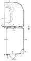
- first trough-shaped chamber 2 for receiving a dirt collecting element, e.g. a filter bag and a second trough-shaped chamber 3 for receiving a blower unit is formed.
- the first and second chambers 2 and 3 are delimited from one another by a partition 4.
- a passage opening 6 provided with grating lamellae 5 is provided.
- a fan unit which can be built into this chamber 3 is connected with its suction opening.
- a receiving space 8 for a cable drum Arranged in the second chamber 3 is a receiving space 8 for a cable drum, which is separated by an intermediate wall 7 from the part of the second chamber 3 which receives the blower unit.
- a protruding inlet connector 9 is formed, to the inlet opening 10 opening into the first chamber 2, the dirt collecting element is coupled.
- the inlet connector 9 is in turn coupled when attaching a vacuum cleaner housing to the inner frame part 1 to a suction connector formed on the vacuum cleaner housing.
- axle journals 12 On the longitudinal walls 11 of the inner frame part 1 laterally projecting axle journals 12 are formed in the area of the second chamber 3. The impellers of the vacuum cleaner are plugged onto these journals 12. Likewise, in the front area of the first chamber 2 there is a receiving recess 14 in the bottom wall 13 thereof provided for the steering wheel of the vacuum cleaner. Since the impellers are arranged directly on the inner frame part, the weight forces of the inner frame part 1 are introduced directly into these wheels, so that the vacuum cleaner housing to be attached to the inner frame part 1 is completely relieved of these weight forces.
- the vacuum cleaner housing to be attached to the inner scaffold part 1 also includes the dust chamber cover necessary for closing the first chamber 2.
- a circumferential sealing element 16 is inserted in a corresponding groove, on which the dust chamber cover comes to rest with a correspondingly designed circumferential edge and thus seals the first chamber 2.
- a post-filter can also be assigned to the blower unit, which at the same time also causes noise reduction.
- a receiving shaft 17 for such a secondary filter is therefore formed on the inner frame part 1 in the area behind the blower unit.
- corresponding fastening elements for screwing and / or latching fastening of the vacuum cleaner housing can be provided thereon.
- the elementary separation of the vacuum cleaner housing and inner scaffold part 1 also offers the advantage that both parts can be optimally designed according to their force.
- a suitable material can also be selected for each part, in particular with regard to the recyclability of these parts.
Landscapes
- Engineering & Computer Science (AREA)
- Mechanical Engineering (AREA)
- Electric Suction Cleaners (AREA)
Applications Claiming Priority (2)
| Application Number | Priority Date | Filing Date | Title |
|---|---|---|---|
| DE19506797 | 1995-02-27 | ||
| DE19506797 | 1995-02-27 |
Publications (2)
| Publication Number | Publication Date |
|---|---|
| EP0730840A2 true EP0730840A2 (fr) | 1996-09-11 |
| EP0730840A3 EP0730840A3 (fr) | 1997-06-11 |
Family
ID=7755148
Family Applications (1)
| Application Number | Title | Priority Date | Filing Date |
|---|---|---|---|
| EP96101678A Withdrawn EP0730840A3 (fr) | 1995-02-27 | 1996-02-06 | Elément de support interne pour aspirateur |
Country Status (1)
| Country | Link |
|---|---|
| EP (1) | EP0730840A3 (fr) |
Cited By (1)
| Publication number | Priority date | Publication date | Assignee | Title |
|---|---|---|---|---|
| WO2002051296A1 (fr) * | 2000-12-22 | 2002-07-04 | Arçelik A.S. | Aspirateur |
Family Cites Families (3)
| Publication number | Priority date | Publication date | Assignee | Title |
|---|---|---|---|---|
| US4527302A (en) * | 1983-11-21 | 1985-07-09 | The Hoover Company | Canister cleaner |
| DE3515667A1 (de) * | 1985-01-24 | 1986-11-06 | Licentia Patent-Verwaltungs-Gmbh, 6000 Frankfurt | Staubsauger |
| FR2641460B1 (fr) * | 1989-01-12 | 1993-04-09 | Moulinex Sa | Procede d'assemblage des elements d'un boitier d'aspirateur et boitier assemble selon un tel procede |
-
1996
- 1996-02-06 EP EP96101678A patent/EP0730840A3/fr not_active Withdrawn
Cited By (1)
| Publication number | Priority date | Publication date | Assignee | Title |
|---|---|---|---|---|
| WO2002051296A1 (fr) * | 2000-12-22 | 2002-07-04 | Arçelik A.S. | Aspirateur |
Also Published As
| Publication number | Publication date |
|---|---|
| EP0730840A3 (fr) | 1997-06-11 |
Similar Documents
| Publication | Publication Date | Title |
|---|---|---|
| DE102005022851B4 (de) | Multizyklon-Staubsammelvorrichtung | |
| DE4037442A1 (de) | Anordnung zur laermverminderung bei staubsaugern | |
| DE3326991C2 (fr) | ||
| DE10313308A1 (de) | Staubsammelfilter für Staugsauger und Staubsauger mit einem solchen Filter | |
| DE19733687A1 (de) | Motorgebläse für ein Reinigungsgerät | |
| DE4131716A1 (de) | Ansaugluftfilter fuer insbesondere kraftfahrzeuge | |
| DE3517329A1 (de) | Staubsauger mit einem scheibenfilter | |
| DE4317715C1 (de) | Filterkassette für einen Staubsauger | |
| EP0730840A2 (fr) | Elément de support interne pour aspirateur | |
| EP0687492B1 (fr) | Plaque filtrante à membrane pour une filtre-presse | |
| DE69621058T2 (de) | Filter- und Abzughaube mit Regelung des Luftstromes | |
| DE19737531C2 (de) | Wärmetauscherbausatz und Klimatisierungsmeßgerät | |
| EP0396803A1 (fr) | Dispositif de filtrage pour un aspirateur de poussières | |
| DE102008023311A1 (de) | Umluftweiche sowie Verfahren zum Montieren einer Umluftweiche | |
| EP1576319A1 (fr) | Boitier pour une hotte aspirante comportant un caisson de ventilateur aspirant | |
| EP0461443B1 (fr) | Aspirateur avec une partie pour amortir le bruit montable sur le moteur de l'agrégat ventilateur | |
| DE2714459C2 (de) | Seitenkanalverdichter | |
| DE10241115B4 (de) | Abdichtungsvorrichtung für Lager | |
| EP0260501A1 (fr) | Pompe entraînée par un électromoteur | |
| DE3515667A1 (de) | Staubsauger | |
| DE2912078A1 (de) | Staubsauger | |
| EP0177840B1 (fr) | Corps pour un aspirateur de poussières à main | |
| DE102004043069A1 (de) | Dunstabzugshaube | |
| DE19963030A1 (de) | Kombinierte Scheiben- und Trommelbremse mit eienr innenbelüfteten Bremsscheibe | |
| DE2705977A1 (de) | Belueftungseinrichtung |
Legal Events
| Date | Code | Title | Description |
|---|---|---|---|
| PUAI | Public reference made under article 153(3) epc to a published international application that has entered the european phase |
Free format text: ORIGINAL CODE: 0009012 |
|
| AK | Designated contracting states |
Kind code of ref document: A2 Designated state(s): DE ES FR GB IT NL SE |
|
| RAP1 | Party data changed (applicant data changed or rights of an application transferred) |
Owner name: BOSCH-SIEMENS HAUSGERAETE GMBH |
|
| PUAL | Search report despatched |
Free format text: ORIGINAL CODE: 0009013 |
|
| AK | Designated contracting states |
Kind code of ref document: A3 Designated state(s): DE ES FR GB IT NL SE |
|
| STAA | Information on the status of an ep patent application or granted ep patent |
Free format text: STATUS: THE APPLICATION HAS BEEN WITHDRAWN |
|
| 18W | Application withdrawn |
Withdrawal date: 19971024 |