EP0730890A2 - Appareil pour modifier la dureté, l'élasticité et la rigidité d'une luge - Google Patents
Appareil pour modifier la dureté, l'élasticité et la rigidité d'une luge Download PDFInfo
- Publication number
- EP0730890A2 EP0730890A2 EP96102253A EP96102253A EP0730890A2 EP 0730890 A2 EP0730890 A2 EP 0730890A2 EP 96102253 A EP96102253 A EP 96102253A EP 96102253 A EP96102253 A EP 96102253A EP 0730890 A2 EP0730890 A2 EP 0730890A2
- Authority
- EP
- European Patent Office
- Prior art keywords
- lever
- control mechanism
- eccentric
- bolt
- stiffening
- Prior art date
- Legal status (The legal status is an assumption and is not a legal conclusion. Google has not performed a legal analysis and makes no representation as to the accuracy of the status listed.)
- Withdrawn
Links
Images



Classifications
-
- A—HUMAN NECESSITIES
- A63—SPORTS; GAMES; AMUSEMENTS
- A63C—SKATES; SKIS; ROLLER SKATES; DESIGN OR LAYOUT OF COURTS, RINKS OR THE LIKE
- A63C5/00—Skis or snowboards
- A63C5/06—Skis or snowboards with special devices thereon, e.g. steering devices
- A63C5/07—Skis or snowboards with special devices thereon, e.g. steering devices comprising means for adjusting stiffness
Definitions
- the invention relates to a device for changing the hardness, elasticity or rigidity of a gliding device for snow, in particular an alpine ski or snowboard, which gliding device has a curvature height predetermined by the factory, with a stiffening device which can be attached to the gliding device and which acts on the gliding device a control mechanism is changeable.
- Such a device is disclosed in DE-PS 12 98 024, according to which a cam-operated adjustment system, which allows the hardness of the ski to be changed via push rods.
- the push rods are located below the top of the ski and the push rods are adjusted using cams or threaded spindles. Due to the discontinuous cam curvature, the setting force is greater than the fixing force when the adjustment system is actuated, which means that additional force is required.
- an arrangement of this known device in the ski body is cumbersome and can only be carried out at the factory.
- FR-PS-1,118,857 describes a stiffening device with a pressure rod lying on the upper side of the ski, the adjusting spindle being shown partially above / below the upper side of the ski.
- a control mechanism is disclosed in FR-PS-1.109.560, in which the stiffening takes place via two toggle lever systems coupled to one another.
- Pre-curved rods are described in U.S. Patent 4,221,400. These are made in cylindrical bores that run in the ski in the direction of the longitudinal axis. Rotation of these rods changes the curvature, hardness and stiffness of the ski. The simultaneous actuation Several bars can be described as complex, with the fact that the effort is considerable.
- DE-OS-33 15 638 describes a stiffening device with a tension band running essentially parallel to the upper side of the ski, the stiffening forces being introduced from the tension band into the ski via vertically arranged adjustment devices.
- FR-OS-2,448,360 A similar system is specified in FR-OS-2,448,360.
- a stiffening device is provided which is raised in the vertical direction and which can result in technical driving risks and contamination problems of the stiffening device.
- FR-PS-2,689,411 A further known technical solution is given in FR-PS-2,689,411, in which a two-part stiffening body is provided which is divided in the middle and is connected elastically or rigidly to the upper side of the ski.
- the type of separation gap between the rear and front is used. By inserting elastic elements in the gap, a stepped bending characteristic in one direction is achieved, but an arbitrary change in the rigidity of the ski is not made possible by the user.
- the FR-PS-2,690,078 stiffens the ski dynamically in one direction while driving by means of a knee lever and the heel pressure exerted by the rear of the ski boot, which acts on the stiffening device.
- DE-GM-91 16 875.9 describes a support plate arrangement in which the support plate is stiffened by a cam or a flyweight.
- a stiffening rod is disclosed in WO94 / 08669, which is mounted higher against the top of the ski is and describes continuous adjustment via a thread adjustment disc.
- FR-PS-2,649.902 discloses a support plate which is mounted higher than the top of the ski and is elastically mounted and stiffenable in the direction of the axis of the ski for a complete safety bond.
- the invention has for its object to be able to make a device for changing the curvature height and thus the hardness, elasticity or rigidity of a gliding device of the type mentioned.
- the driving properties should be able to be adapted to the state of the art to a greater extent than the slope conditions.
- the problem is solved by the characterizing features stated in claim 1.
- the configuration according to the invention not only enables manual actuation of the control mechanism, but also a continuous adjustment of the arch height due to its configuration and thus the hardness, elasticity or rigidity of the glider.
- claim 2 also enable bidirectional actuation, increasing or decreasing the curvature height. Further advantageous and inventive configurations result from claims 3 to 16, 24 and 25.
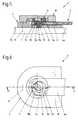
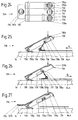
- FIGS. 5 to 10 show a first exemplary embodiment of a control mechanism, FIG. 5 a longitudinal section along the line VV of FIG. 6 through the control mechanism in the neutral position, FIG. 6 a top view of FIG. 5 but without a handwheel, FIG. 7 a section along the line VII-VII in FIG.
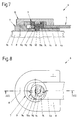
- FIGS. 11 to 14 represent two further exemplary embodiments of control mechanisms, with FIG. 11 a longitudinal section along the line XI-XI of FIG. 12 and FIG. 12 a section along the line XII-XII of FIG. 11 of a second variant of the Control mechanism, the Fig. 13 shows a longitudinal section along the line XIII-XIII of Fig. 14 and Fig. 14 shows the plan view of Fig.
- FIGS. 17 and 18 show a front view and a top view of a fifth exemplary embodiment of the control mechanism, FIG. 17 showing a section along the line XVII-XVII in FIG. 18 and FIG. 18 a section along the line XVIII-XVIII in FIG.
- FIGS. 19 and 20 show a front view and a top view of a sixth variant of a control mechanism, FIG. 19 showing a longitudinal section along the line XIX-XIX of FIG. 20 and FIG. 20 a section along the line XX-XX of FIG. 19.
- FIGS. 19 showing a longitudinal section along the line XIX-XIX of FIG. 20 and FIG. 20 a section along the line XX-XX of FIG. 19.
- FIGS. 19 showing a longitudinal section along the line XIX-XIX of FIG. 20 and FIG. 20 a section along the line XX-XX of FIG. 19.
- FIGS. 19 showing a longitudinal section along the line XIX-
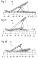
- FIGS. 21, 22 and 23 represent - again in a schematic representation - a seventh variant of the control mechanism.
- FIGS. 24 to 27 show an eighth embodiment of a modification of the seventh variant of a control mechanism.
- FIG. 28 shows an embodiment of a spring system in a partially sectioned top view.
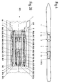
- FIG. 1 to 4 schematically show a ski 1, on the top 1a of which a toe 2 and a heel holder 3 are attached. Furthermore, a stiffening device 4 is attached to the ski 1, the rear portion 4b of which is attached with its end in the spring system 5 in the immediate vicinity of the heel holder 3.
- the front section 4a passes through the front jaw 2 and its end section engages with a ski-fixed control mechanism 6.
- each ski has a so-called camber height h o which is determined by the factory and is not shown separately in the drawing.
- 1 shows the ski 1 with the above-mentioned components in the inactive position of the control mechanism 6 with the curvature height h 1.
- the ineffective position is also referred to in the following as a neutral position or neutral position.
- FIG. 2 shows the ski 1 in a position in which the control mechanism 6 brings the ski under pressure to an increased curvature height h 2 compared to its neutral position.
- FIG. 3 relates to such a position of the control mechanism 6, which shows a decrease in the curvature height to h 3 compared to that of the neutral position with the curvature height h 1 corresponds.
- the ski can be adapted to the respective slope conditions in a manner desired by the user.
- the control mechanism 6 consists of a base body 7 which is fastened on the ski 1 by means of only indicated screws 8 and in which base body 7 the front section 4a of the stiffening device 4 is guided in a horizontally sliding manner.
- An eccentric body 9 has two parts which are offset in the vertical direction and concentric with respect to the central axis 18, namely an upper part 9a and a lower part 9b, between which the actual eccentric 9d is arranged.
- the eccentric body 9 is supported by means of the two mutually concentric parts 9a and 9b in the base body 7 and engages with its eccentric 9d in an elongated recess 4c of the front section 4a of the stiffening device 4.
- a handwheel 10 Arranged on the base body 7 is a handwheel 10 which is independent of this and which, by means of a coupling pin 10a fastened thereon, engaging in an elongated recess 9c of the upper part 9a of the eccentric body 9 produces a positive connection between the eccentric body 9 and the handwheel 10.
- the eccentric 9d with its longitudinal axis is normal to the longitudinal axis of the stiffening device 4.
- the eccentric body 9 is rotated about its axis by the interaction of the coupling pin 10a and the elongated recess 9c.
- the eccentric 9d thereby sets the front section 4a of the stiffening device 4 to the left or right, depending on the direction of rotation. If the handwheel 10 is turned to the right, the stiffening device 4 also moves to the right, ie to the rear, as shown in FIGS. 7 and 8.
- the control mechanism 6 is in this position the ski 1 in the position shown in FIG. 2 and has the curvature height h 2 .
- the stiffening device 4 When the handwheel 10 is turned to the left, the stiffening device 4 according to FIGS. 9 and 10 moves into a position which is shifted to the left, ie to the front. In this position of the control mechanism 6, the ski 1 is in the position according to FIG. 3 and has the curvature height h 3 .
- the control mechanism 106 has an eccentric body 109 with a centering pin 114 passing through it.
- the eccentric body 109 is mounted in the base body 107 by means of the centering pin 114.
- a pivot bearing 112 is provided for a folding lever 113 pivotable about a transverse axis 112a.
- the folding lever 113 allows the eccentric body 109 to be rotated slightly about a vertical axis 118 of the centering pin 114 in two directions with respect to its neutral position, as a result of which the front section 4a of the stiffening device 4, with its oval recess 4c, is also positively connected to the eccentric 109d corresponding relative movements with respect to the base body 107 are carried out, as a result of which the curvature height of the ski can be adjusted bilaterally, as already described.
- an adjusting disk 215 is rotatably mounted by means of grip tabs 215a in a base body 207 which is independent of the ski 1 and is connected to it by means of only indicated screws 8 about the vertical axis 218 of the centering pin 214.
- the driver 216 and thereby also the stiffening device 4 perform movements in the direction of the longitudinal axis of the stiffening device 4 due to the design of the continuously increasing contour of the control groove 217 Connection between the front section 4a of the stiffening device 4 and the driver 216, the movements of the stiffening device 4 take place both in terms of size and in the direction according to those which were caused by the adjusting disk 215.
- a base body 307 on the upper side 1a of the ski, which is connected to the ski 1 by screws (not shown).
- the base body 307 has a front and a rear stop surface 321 and 322, respectively.
- a hand lever 320 is articulated on a horizontal transverse axis 319.
- a reversing lever 323 is articulated on the underside and in the central region thereof.
- a stop body 324 is articulated on the side of the reversing lever 323 facing away from the hand lever 320.
- the parts 319 to 324 thus form a kind of toggle mechanism.
- a folding lever 413 is pivotally mounted on the eccentric upper part 409a of the eccentric body 409 in a pivot bearing 412 on its transverse axis 412a.
- An intermediate piece 426 is provided with a first elongated hole 427, in which the eccentric 409d engages.
- the base body 407 is provided with a pivot pin 425, around which the intermediate piece 426 can perform pivoting movements.
- a driver 416 of the front section 4a of the stiffening device 4 is guided with play.
- the eccentric 409d describes an eccentric circular arc with its center.
- the intermediate piece 426 is entrained by the eccentric 409d which moves along the elongated hole 427 and thereby performs a rotary movement about the pivot pin 425.
- the driver 416 slides in the second elongated hole 428 and thereby displaces the stiffening device 4 in its axial direction.
- the distance between the driver 416 and the base body 407 is either increased or decreased, and the stiffening device 4 is put under pressure or tension, which brings about the bidirectional change in the curvature height on the ski (see FIGS. 2 and 3).
- a base body 507 is fastened on the upper side 1a of a ski 1 by means of screws 8 which are only indicated.
- the front section 4a of the stiffening device 4 is slidably mounted and has a firmly connected driver 516 on its end closest to the base body 507.
- the centering pin 514 which has the vertical axis 518, is mounted in the base body 507 and in turn serves to support the eccentric body 509.
- the intermediate piece 526 which is coupled to the eccentric 509, follows its movement and, after the clearance between the elongated hole 527 and the driver 516 has been bridged, displaces the front section 4a of the stiffening device 4 via the driver 516
- the distance between the base body 507 and the front section 4a of the stiffening device 4 is either increased or decreased, which brings about the bidirectional change in the curvature height of the ski.
- an axis 630 mounted on the ski 1 in a bearing (not shown) is arranged on the upper side 1a of the ski 1.
- a neutral lever 631, a pull lever 632 and a pressure lever 633 are pivotably attached to this axis 630.
- a tension connection lever 634 is rotatably mounted on the tension lever 632, which on the other hand connects to the front section 4a of the stiffening device 4 is pivotally connected by means of a draw bolt 636.
- a pressure connection lever 635 is articulated on the pressure lever 633, which is also connected at its end facing away from the pressure lever 633 by means of a pressure bolt 637 to the front section 4a of the stiffening device 4 so that it can rotate. If the pull lever 632 or the push lever 633 is in the active position, the neutral lever 631 serves to move the other lever 633 or 632 to the neutral position before the other lever 633 or 632 is actuated, in order to prevent the pull lever 632 and push lever 633 from simultaneously the effective situation will be brought. After a previous actuation of the neutral lever 631, the pressure lever 633 was now pressed downward according to FIG.
- the pressure connection lever 635 thereby comes into an approximately horizontal position, whereby the front section 4a of the stiffening device 4 is subjected to pressure via the pressure pin 637, see arrow P 2 , and the curvature height of the ski, corresponding to FIG. 2 , is increased to h 2 . If the curvature height is now to be reduced, the neutral lever 631 is first actuated, as a result of which the pressure lever 633 becomes ineffective and the front section 4a of the stiffening device is de-energized.
- the pull connecting lever 634 comes into an approximately horizontal position and, by moving the pull bolt 636 in the direction of arrow P 1, causes a tensile stress on the front section 4a of the stiffening device 4, thereby increasing the curvature of the ski according to FIG. 3 to h 3 is reduced.
- the eighth variant of the control mechanism 706 according to FIGS. 24 to 27 is a further development of the previous seventh variant.
- the transverse axis 730 is mounted in a bearing, not shown, on which the neutral lever 731 with an associated opening spring 731a, the tension lever 732 with an associated opening spring 732a and the pressure lever 733 with an associated opening spring 733a are pivotably arranged .
- the front section 4a of the stiffening device 4 as shown in FIGS A draw bolt 736 and a pressure bolt 737 are attached substantially at right angles to the longitudinal axis of the stiffening device 4.
- a tension connection lever 734 is articulated on the tension bolt 736, a cross bolt 734a engaging in its upper end section in a hook-shaped recess 739 of the tension lever 732 provided with hooks 739a and in a longitudinal groove 740 of the neutral lever 731 (see Figures 24 and 27), and one Leg spring 734b causes the tension connecting lever 734 to bear against the hook-shaped recess 739 of the tension lever 732.
- a pressure connection lever 735 is connected in an articulated manner to the pressure pin 737. This engages with its transverse bolt 735a into a hook-shaped recess 739 'of the pressure lever 733 provided with a hook 739'a and into the longitudinal groove 740, as shown in FIGS.
- a leg spring 735b causes the pressure connection lever 735 to rest against the hook-shaped recess 739 'of the pressure lever 733.
- the tension lever 732 and the pressure lever 733 each have a recess 732b, 733b
- the neutral lever 731 has two recesses 731b, 731'b provided, in order to offer a better grip when operating with a ski pole.
- the second recess 731'b of the neutral lever 731 is formed on an extension 731c.
- the pressure lever 733 and neutral lever 731 also come to rest horizontally without having any effect.
- the hook 739'a of the hook-shaped recess 739 'of the pressure lever 733 comes into engagement with the cross bolt 735a of the pressure connection lever 735.
- the front section 4a of the stiffening device 4 moves in the direction indicated by the arrow P 2 in FIG. 26.
- Pull lever 732 and neutral lever 731 also assume a horizontal position due to the coupling with the longitudinal groove 740 of the neutral lever 731.
- the invention also relates to the special configuration of a spring system which is to be protected by the characterizing features of claim 17. Due to the measures contained in this claim, a power transmission for changing the springs provided in the spring system is manually and continuously set via the control mechanism and also changed in its direction of action. Further advantageous configurations of this spring system result from claims 18 to 23 and from the description which now follows.
- the coil springs used were also referred to as springs for the sake of simplicity and general designation.
- the stop plates 842, 843, 844 and the end part 845 are guided on guide surfaces 841a, 841b, 841c and 841d of the bearing body 841.
- the front stop plate 842 has a pin 842a. Symmetrical to the longitudinal axis of the stiffening device 4 are formed in the same threaded bores 846a, 846b, which are used to receive one screw 847a, 847b.
- the screws 847a, 847b each serve to guide a spring 848a, 848b arranged between the front stop plate 842 and the middle stop plate 843.
- the shafts of the screws 847a and 847b slide in bores in the front, middle and rear stop plates 842, 843 and 844, and in the end part 845.
- the screws 847a, 847b are slidably supported in the end part 845 by means of their heads 847c, 847d.
- a through hole 845a is also formed in the end part 845, through which a threaded bolt 849 is screwed into a through thread of the rear stop plate 844.
- a forward-facing pin 849a is formed on the threaded bolt 849.
- the pin 842a of the front stop plate 842 and the pin 849a of the threaded bolt 849 serve to center another coil spring 848c.
- the bolts 847a, 847b are also moved to the left by their anchoring in the threaded bores 846a, 846b and act on the end part 845 via their heads 847c, 847d and subsequently also take the rear stop plate 844 with them.
- the middle stop plate 843 is also displaced via the threaded bolt 849 screwed to the rear stop plate 844.
- a further embodiment according to the invention is characterized in that the control mechanism is equipped with a device for displaying the degree of stiffening or the bulge height of the gliding device, with either a mark on the base body and markings on the rotatable component or on the handle, preferably with dimensions, being provided .
- the arrangement of the mark can also be interchanged with that of the markings.
Landscapes
- Footwear And Its Accessory, Manufacturing Method And Apparatuses (AREA)
- Vehicle Body Suspensions (AREA)
- Springs (AREA)
Applications Claiming Priority (2)
| Application Number | Priority Date | Filing Date | Title |
|---|---|---|---|
| AT428/95 | 1995-03-10 | ||
| AT0042895A AT403250B (de) | 1995-03-10 | 1995-03-10 | Vorrichtung zum verändern der härte, elastizität oder steifigkeit eines gleitgerätes |
Publications (2)
| Publication Number | Publication Date |
|---|---|
| EP0730890A2 true EP0730890A2 (fr) | 1996-09-11 |
| EP0730890A3 EP0730890A3 (fr) | 1998-09-16 |
Family
ID=3490352
Family Applications (1)
| Application Number | Title | Priority Date | Filing Date |
|---|---|---|---|
| EP96102253A Withdrawn EP0730890A3 (fr) | 1995-03-10 | 1996-02-15 | Appareil pour modifier la dureté, l'élasticité et la rigidité d'une luge |
Country Status (2)
| Country | Link |
|---|---|
| EP (1) | EP0730890A3 (fr) |
| AT (1) | AT403250B (fr) |
Cited By (4)
| Publication number | Priority date | Publication date | Assignee | Title |
|---|---|---|---|---|
| AT405371B (de) * | 1997-07-07 | 1999-07-26 | Tyrolia Freizeitgeraete | Skibindung |
| WO2001091861A1 (fr) * | 2000-06-02 | 2001-12-06 | Atomic Austria Gmbh | Element de renforcement et/ou d'amortissement pour dispositif de glissement, notamment pour ski ou planche a neige |
| EP2106828A1 (fr) | 2008-04-02 | 2009-10-07 | ATOMIC Austria GmbH | Appareil de glisse de type planche doté d'un dispositif de réglage destiné à la modification du comportement d'utilisation |
| FR2958507A1 (fr) * | 2010-04-12 | 2011-10-14 | Marc Kuntz | Semelle a rigidite ajustable |
Family Cites Families (5)
| Publication number | Priority date | Publication date | Assignee | Title |
|---|---|---|---|---|
| FR1170571A (fr) * | 1957-04-03 | 1959-01-15 | Régleur de cambrure pour ski | |
| DE1302470B (fr) * | 1962-01-09 | |||
| FR2654635A1 (en) * | 1989-11-22 | 1991-05-24 | Salomon Sa | Device for mounting a boot on a ski |
| US5320377A (en) * | 1991-06-14 | 1994-06-14 | Ruffinengo Piero G | Apparatus for selectivity varying the stiffness of a ski |
| DE59300960D1 (de) * | 1992-10-22 | 1995-12-21 | Baumann & Cie Ag | Vorrichtung zum einstellen der vorspannung bzw. durchbiegung bei snowboards oder skis und deren verwendung. |
-
1995
- 1995-03-10 AT AT0042895A patent/AT403250B/de not_active IP Right Cessation
-
1996
- 1996-02-15 EP EP96102253A patent/EP0730890A3/fr not_active Withdrawn
Cited By (5)
| Publication number | Priority date | Publication date | Assignee | Title |
|---|---|---|---|---|
| AT405371B (de) * | 1997-07-07 | 1999-07-26 | Tyrolia Freizeitgeraete | Skibindung |
| WO2001091861A1 (fr) * | 2000-06-02 | 2001-12-06 | Atomic Austria Gmbh | Element de renforcement et/ou d'amortissement pour dispositif de glissement, notamment pour ski ou planche a neige |
| US6883823B2 (en) | 2000-06-02 | 2005-04-26 | Atomic Austria Gmbh | Stiffening and/or damping element for a sliding device, especially for a ski or snowboard |
| EP2106828A1 (fr) | 2008-04-02 | 2009-10-07 | ATOMIC Austria GmbH | Appareil de glisse de type planche doté d'un dispositif de réglage destiné à la modification du comportement d'utilisation |
| FR2958507A1 (fr) * | 2010-04-12 | 2011-10-14 | Marc Kuntz | Semelle a rigidite ajustable |
Also Published As
| Publication number | Publication date |
|---|---|
| ATA42895A (de) | 1997-05-15 |
| AT403250B (de) | 1997-12-29 |
| EP0730890A3 (fr) | 1998-09-16 |
Similar Documents
| Publication | Publication Date | Title |
|---|---|---|
| EP0294402B1 (fr) | Systeme de reglage pour fixations de ski | |
| AT404096B (de) | Vorrichtung zum verändern der härte, elastizität oder steifigkeit eines gleitgerätes | |
| DE2709694A1 (de) | Skistiefel mit einem system zum halten des vorderfusses, insbesondere mit hilfe von baendern | |
| DE4106401C2 (de) | Snowboard-Bindung | |
| EP3120903A1 (fr) | Talonnière | |
| AT403250B (de) | Vorrichtung zum verändern der härte, elastizität oder steifigkeit eines gleitgerätes | |
| DE2212017A1 (de) | Sicherheitsskibindung | |
| DE1578959C3 (de) | Fersenabstützvorrichtung für Sicherheitsskibindungen | |
| EP0061590B1 (fr) | Frein de ski | |
| AT390380B (de) | Sicherheitsskibindung | |
| DE4435960C2 (de) | Snowboardbindung | |
| DE3124853C2 (de) | Backen, insbesondere Vorderbacken für eine Auslöseskibindung | |
| DE1956653A1 (de) | Vorderbacken fuer Sicherheits-Skibindungen | |
| EP0547531B1 (fr) | Machoire avant | |
| DE2133267C3 (de) | Vorderabstützvorrichtung für Sicherheitsskibindungen | |
| EP0250809A2 (fr) | Mâchoires avant de fixation de sécurité pour ski | |
| EP0935489A1 (fr) | Dispositif de modification de l'inclinaison laterale d'une chaussure de ski | |
| EP0415006B1 (fr) | Mâchoire avant | |
| EP3095492B1 (fr) | Mâchoire avant d'une fixation de sûreté | |
| DE3311940C2 (de) | Klebstoffauftragvorrichtung in einer Klebezwickmaschine | |
| EP2851108B1 (fr) | Mâchoire avant pour une fixation de ski | |
| AT397350B (de) | Sicherheitsskibindung | |
| DE102005044149B4 (de) | Skibindung, insbesondere für den Tourenlauf | |
| AT405371B (de) | Skibindung | |
| AT371009B (de) | Skibremse |
Legal Events
| Date | Code | Title | Description |
|---|---|---|---|
| PUAI | Public reference made under article 153(3) epc to a published international application that has entered the european phase |
Free format text: ORIGINAL CODE: 0009012 |
|
| AK | Designated contracting states |
Kind code of ref document: A2 Designated state(s): CH DE FR LI |
|
| PUAL | Search report despatched |
Free format text: ORIGINAL CODE: 0009013 |
|
| AK | Designated contracting states |
Kind code of ref document: A3 Designated state(s): CH DE FR LI |
|
| 17P | Request for examination filed |
Effective date: 19990316 |
|
| 17Q | First examination report despatched |
Effective date: 20010608 |
|
| STAA | Information on the status of an ep patent application or granted ep patent |
Free format text: STATUS: THE APPLICATION IS DEEMED TO BE WITHDRAWN |
|
| 18D | Application deemed to be withdrawn |
Effective date: 20010821 |