EP0730932B1 - Bandspanner - Google Patents
Bandspanner Download PDFInfo
- Publication number
- EP0730932B1 EP0730932B1 EP96103026A EP96103026A EP0730932B1 EP 0730932 B1 EP0730932 B1 EP 0730932B1 EP 96103026 A EP96103026 A EP 96103026A EP 96103026 A EP96103026 A EP 96103026A EP 0730932 B1 EP0730932 B1 EP 0730932B1
- Authority
- EP
- European Patent Office
- Prior art keywords
- strap
- loop
- clamping device
- clamping
- spindle
- Prior art date
- Legal status (The legal status is an assumption and is not a legal conclusion. Google has not performed a legal analysis and makes no representation as to the accuracy of the status listed.)
- Expired - Lifetime
Links
Images






Classifications
-
- B—PERFORMING OPERATIONS; TRANSPORTING
- B25—HAND TOOLS; PORTABLE POWER-DRIVEN TOOLS; MANIPULATORS
- B25B—TOOLS OR BENCH DEVICES NOT OTHERWISE PROVIDED FOR, FOR FASTENING, CONNECTING, DISENGAGING, OR HOLDING
- B25B1/00—Vices
- B25B1/20—Vices for clamping work of special profile, e.g. pipes
- B25B1/205—Vices of the chain or strip type
-
- B—PERFORMING OPERATIONS; TRANSPORTING
- B25—HAND TOOLS; PORTABLE POWER-DRIVEN TOOLS; MANIPULATORS
- B25B—TOOLS OR BENCH DEVICES NOT OTHERWISE PROVIDED FOR, FOR FASTENING, CONNECTING, DISENGAGING, OR HOLDING
- B25B5/00—Clamps
- B25B5/14—Clamps for work of special profile
-
- B—PERFORMING OPERATIONS; TRANSPORTING
- B25—HAND TOOLS; PORTABLE POWER-DRIVEN TOOLS; MANIPULATORS
- B25B—TOOLS OR BENCH DEVICES NOT OTHERWISE PROVIDED FOR, FOR FASTENING, CONNECTING, DISENGAGING, OR HOLDING
- B25B5/00—Clamps
- B25B5/14—Clamps for work of special profile
- B25B5/142—Clamps for work of special profile for windows and frames
Definitions
- the invention relates to a strap tensioner with a strap, which is used to wrap one or more workpieces forms an outer loop with a tensioning device, relative to which a first end of the loop can be fixed, by means of which is the outer loop for clamping the workpiece or of the workpieces is contractible and which one on the Loop with a loop element supported base element as well as a tension element, with an adjusting device, by means of which the tension element and the basic element are movable relative to each other, with a relative movement the outer loop of the basic element and tension element is contractible under the action of a pulley.
- Such a belt tensioner according to the preamble of independent claim 1 is known from US 3,584,860 and is used for reclamping workpieces of various types Forms, whereby a tensioning of the tape according to the principle of a simple pulley.
- the tensioning device is designed so that it pulls on both ends of the outer loop, which as Tension tape used textile tape when tensioning on two rollers is wound up.
- this solution has the disadvantage that due to the different circumferential dimensions when winding uneven pulling of the tension band on the rollers on both sides of the outer loop.
- a position serves for free pulling out of the tensioning strap, one for quick Winding up the strap and a third position for Tension the strap in small rest positions.
- Such belt tensioners are particularly suitable for holding together bulky parts or parts with interrupted peripheral surfaces, such as B. backrests or feet.
- To the misshapen parts also include pillars, kidney-shaped furniture or oval-round workpieces.
- normal frames can also be used Square, hexagonal or octagonal shape.
- Belt tensioners come in a wide variety of designs known.
- belt tensioners are known, in which a Lashing strap with ratchet is used.
- Other embodiments of tape tensioners use a spindle with Spindle nut for operating the tape guide. With these Solutions are required, however, the two hinge sides or tape ends, holding the Band depends on how good the clamping is.
- the invention is therefore based on the object Belt tensioner of the generic type to improve such that this can be handled as advantageously as possible.
- the belt tensioner according to the invention is simple can be actuated because only to pull the outer loop together a relative movement between the basic element and tension element can be carried out by means of the adjusting device.
- the size the sling can be varied to fit different
- the size of the loop is provided with a fixing device, with which the two ends can be fixed in the clamping device are.
- a particularly advantageous embodiment due to its simplicity provides that the noose with a first Place on the basic element and with at least two more Places on the traction element is attacking.
- the loop is two Loops forms, the bends the two other places form with which the loop abuts the tension element. With these two loops the is easy Effect of the double pulley can be represented, preferably one end of each loop at each end The loop lies and at the other end of the loop the strap continues to the outer loop.
- a particularly simple embodiment of the invention Belt tensioners provide that a first end of the Loop arranged at a fixed point on the strap is and that the strap is over a second end the noose continues as a strap reserve and that the size of the sling by reducing or enlarging the Tension strap reserve is variable, the size of the sling by exact positioning of the first end relative to the second end is definable.
- first and second ends of the loop could be arranged on a separate locking device which is used to vary the size of the sling.
- the first end in the jig prefferably be determined independently of the fixing device.
- a particularly useful solution provides that the first end and the second end in the fixing device of the Clamping device can be fixed so that the tensile force on one End of the noose immediately to the other end of the Noose works.
- both first end as well as the second end of the noose in the Fixing device can be fixed, since then the fixing device affects both ends and, for example, both ends presses against each other, which is particularly the case with one braided or textile strap due to the high surface friction leads to the fact that in the fixing device both ends immediately due to the friction between them are fixed relative to each other.
- the fixing device can be of various types and Be done wisely.
- An advantageous embodiment of the Fixing device provides that this is a fixing element and has an abutment between which the strap can be clamped is.
- the strap between the fixing element and the abutment can in principle be a separate actuating device, for example, provided with a toggle mechanism his.
- a particularly easy to use solution provides that the fixing device and the adjusting device at the same time, in particular by means of the same actuating element, can be operated, so that in addition to easy handling it is also ensured that when actuating the adjusting device for tensioning the strap Fixing device in the sense of defining at least one End of the loop is actuated.
- a particularly advantageous embodiment of the invention Solution provides that the fixing element when moving the base element and the tension element relative can be actuated relative to one another by the adjusting device.
- the adjusting device via the fixing device on the base element supports and thus the fixing device at least that second end of the loop and possibly also the first Fixed end relative to the basic element.
- the Tension element has two tensile bodies, one of which each in one of the at least two other places on the Noose works.
- the tension members are preferably on both sides of the adjusting device arranged on the tension element.
- Such a spindle has the advantage that it is easier Operability is able to a relatively large distances generate high power, which is particularly the case here Case in which the relative movement between the tension element and Basic element of a double pulley system on the outside Has noose that matters.
- the Spindle with one spindle end on the fixing element of the Fixing device supports.
- Relatively rotatably relative to the tension element carrying the spindle nut leading to the adjusting spindle is preferably provided that the tension element is connected to the base element Linear guide in the direction of this and away from it movable, but is non-rotatably guided.
- This linear guide could be of various types and Be trained.
- An advantageous training of Linear guide provides that this part of a housing, preferably formed by walls of the same, on which in particular the basic element is held.
- the basic element Part preferably a bottom part, of the housing forms.
- the guide openings are preferably laid in such a way that that the respective run of the sling after the each loop formed between the base element and tension element extends through the respective guide opening.
- the tensioning device a carrier for the strap reserve has, on which in particular the strap reserve can be filed in an orderly manner.
- This carrier is preferably used as a winding body for the Strap reserve formed, on which thus the Can wind up the strap reserve in an orderly manner.
- the winding body could on the one hand through the housing itself be formed so that the strap reserve is easy can wind the winding body formed by the housing.
- the winding body is a forms rotatable coil relative to the housing on which the Tension band reserve can be wound up in the form of a wrap.
- the spool is preferably with a crank for winding of the strap reserve rotatable.
- corner elements could, for example, be used for the workpieces wrapping the outer loop freely between Strap and the respective workpieces can be inserted.
- This has the disadvantage, however, that it is easy to use of the belt tensioner according to the invention is no longer possible.
- corner elements are captively fixable on the strap.
- the corner elements are preferably used for fixing to the strap provided with holding elements acting on the strap, who are trained in a variety of ways could be.
- a particularly advantageous embodiment provides that the holding elements are designed so that the strap is transverse to its longitudinal direction in one through the holding elements fixed position on the corner elements can be inserted, so that there is no need to close the outer loop open and for example the strap through this lead through all around.
- the holding elements are preferably designed so that the strap from one side edge to a flat side spread.
- the securing element can be a nose which the tensioning strap lies on with the side edge which is not overlapped by the holding element.
- the securing element also represents a holding element and thus the two holding elements of mutually opposite side edges starting from the tensioning strap.
- the corner elements can be used in many different ways be trained.
- the corner elements have a cavity Grasp in a U-shape and end of the leg of the U Have pressure lugs with which the corner elements on the Workpieces work.
- the corner elements are included so that it can be placed on the corners of workpieces so that the pressure lugs rest on opposite sides of the corners.
- the corner elements can be designed so that they with their pressure noses act directly on the workpiece. Yet however, it is more advantageous if the corner elements in the area their pressure lugs with pivoted on these pressure parts are provided, which in turn have printing areas, with which the printed parts act on the workpiece.
- the printed parts are flat or slightly curved printing surfaces.
- corner elements are designed so that the tensioning band across the full length of the latter rests in order to achieve the best possible pressure effect.
- corner elements are also preferably so trained that the pressure tabs symmetrical to a center line of the strap are arranged.
- the pressure parts are preferably designed such that it is symmetrical to a central plane of the Stretch strap.
- a particularly advantageous embodiment of the invention Band tensioner provides that this for the Clamping workpieces of symmetrical and shapeless Shape with textile tape and several instep areas to be underlaid to protect the workpieces and for better sliding of the Tensioning strap along this when tensioning by means of a usual clamping element within a clamping device or a Tensioning device is formed, the tensioning strap inside of the tensioning device or the tensioning device in tensioning channels of deflection corners - or also called tensile elements - is performed so that the effect of a double Pulley results and preferably with a tensioning Spindle between a pressure plate and the two sides of the strap are clamped to the surrounding housing become.
- Another advantageous variant of the invention Solution provides that two through openings in the housing are present on the workpiece exit side, through which the band on a radius when tensioning inwards is pulled.
- tape guide Has band channels for redirecting to the depth of the bandwidth and to facilitate marking when necessary firmly manufactured preferably as an injection molded part made of plastic Part are attached to the open side.
- Cams are preferably attached to the housing for winding serve the tape when storing the tensioning device, and a slot to secure the tape.
- tensioning device or the tensioning device additionally with two or more corner elements or corners to protect the Workpiece edges is equipped and for better sliding of the Tension band around these edges, these for edges or Miter angles from 45 to 120 ° can be used continuously and captive on the strap afterwards are mountable.
- the clamping corner or the corner element is preferably in one piece made from an open cylindrical shape, the Opening is set so that acute angles and obtuse angles have space in the inner cavity of the hollow cylinder.
- the tape guide in a slot that is open at the top and after has an approach at the bottom and an introductory slope at the top and a cam on both sides.
- This cam is expediently formed on the cylinder and has an insertion bevel with a barb functioning Approach to tape backup.
- the approach lies thereby deeper than the slot drain.
- An advantageous embodiment of an inventive Belt tensioner creates the possibility with the simplest ease of use quickly after gripping the workpiece to high Resilience to come.
- the belt tensioner is a compact device with and output trained.
- the belt tensioner is also preferably equipped with Protective or clamping corners for the most common miter angles.
- the tensioning strap When tensioning, the tensioning strap should be drawn in evenly on both sides become.
- the span corners should be stepless for miter angles or spanned corners from 45 to 120 ° can be used can adapt to the manufactured angle and easily resilient. They should be attached to the tape as required can without being unwound or unwound need to quickly switch to clamping with or without Span corners. They should also be captive on the strap hold tight. For storage, it is advantageous that Being able to wind up the strap and the protective corners cannot be lost to attach to the jig.
- a belt tensioner shown as a whole in FIG. 1 comprises one from a tension band 10, preferably a textile band, formed outer loop 12a, which for example two Workpieces 14 and 16 encirclingly wrap around on the outside and to a clamping device designated as a whole by 20 is guided, which serves the outer loop 12a contract.
- the clamping device 20 comprises a housing 22, in which as shown in Fig. 2, a tension element 24 is arranged, by means of an adjusting device designated as a whole by 26 relative to a basic element designated 28, which forms a base of the housing 22 and which has two loop bushings 30 and 32, through which the Tension strap 10 from the outer loop 12a into an interior of the Housing 22 is guided.
- the outer loop 12a is provided with a lock Z with interconnectable and detachable lock elements Z 1 and Z 2 , which makes it possible to open the outer loop 12a in order to be able to put the outer loop 12a around the workpieces 14 and 16 without being able to these have to be pushed through the side of the loop.
- the lock Z creates the possibility, in the event that a particularly large outer loop 12a is required, to open the lock Z and to insert an extension piece between the lock parts Z 1 and Z 2 , which is connected at both ends to the lock part Z 1 or Z 2 has connectable lock parts.
- the tension element 24 comprises, as shown in FIGS. 2 and 3, two side walls 40 and 42 running parallel to one another, between which there is a spindle nut 44 and between which also on both sides of the spindle nut 44 and preferably pull rollers 46 and 48 lying symmetrically to the latter extend, each rotatable on the side walls 42 and 44 are mounted so that their axes of rotation 50 and 52 are preferably parallel and in a perpendicular to an axis 54 of the spindle nut 44 lying level 56.
- the entire tension element 24 is preferably composed of two parts 24a and 24b, the part 24a being the side cheek 40 and storage for the pull rollers 46 and 48 and the Guide rollers 60 and 62 includes which are integral with this are molded. Furthermore, the cheek 40 is also the Spindle nut 44 formed in one piece.
- the second part 24b preferably includes the side cheek 42 as well as receptacles for the bearings of the pull rollers 46 and 48 and the guide rollers 60 and 62 and one on the spindle nut 44 adjacent and additionally stabilizing support element 72.
- the two parts 24a and 24b are through Common securing elements connected together.
- the loop 12 goes out from a first fixable in a fixing device 80 End 82 and forms after the first end with one first loop center 12e one from the fixing device 80 outgoing, U-shaped loop wrapping around the pulling roller 46 84, following which the run 12e through the Loop feedthrough 30 in the form of a curved feedthrough slot through the base element 18 from the housing 22 emerges in order to then the outside of the clamping device 20th to form lying outer loop 12a.
- the tensioning strap 10 also extends over the first end 82 the loop 12 and forms an end piece 86, which the base element 28 fixed by means of a holding pin 88 is, wherein the holding pin 88 is formed by the end piece 86 Passes through eyelet 90.
- a second strand extends 12z of the loop 12 also in the form of a U-shaped Loop 94 over the pull roller 48 to then also through the loop passage 32 in the form of a curved slot in the base element 28 and emerge from the housing 22 to the outside of the jig To form 20 lying outer loop 12a.
- the second end 92 extends Sling 12 the tension band 10 over the fixing device 80 out and forms a strap reserve 96, which over the circumferential surface 64 of the guide roller facing the spindle nut 44 60 of the tension element 24 is guided and in the connection to the guide roller 60 on a spool 98 in the form of a Winding 100 can be wound.
- the coil 98 is, as shown in FIG. 4, between two Side walls 102 and 104 of the housing 22 are arranged and by means of one penetrating the side walls 102 and 104 Shaft 106 rotatably supported about an axis 108. On one side a crank 110 is rotatably connected to the shaft 106, with which the tension band reserve 96 in the form of the winding 100 the coil 98 can be wound up.
- the side walls 102 and 104 also provided with longitudinal slots 112 and 114, in which the pulling element 24 relative in an adjustment direction 116 is movably guided to the base element 28, the tension element 24 in the longitudinal slots 112 and 114 with projections 118 or 120 engages. Furthermore, that is Tension element 24 on inner sides 122 and 124 of the side walls 102 and 104 with outer sides 126 and 128 respectively and is thereby additionally non-rotatable, but in the direction of adjustment 116 slidably guided.
- the longitudinal slots 112 and 114 run parallel to the Adjustment direction 116.
- the movement of the tension element 24 relative to the base element 28 provided adjusting device 26 comprises a spindle 130, which passes through the spindle nut 44 and with her Spindle end 132 engages in a pressure piece 134, which in addition is still provided with a fixing shoe 136.
- Thrust piece 134 is preferably used as a clamp usual clamping spindle equipped with a usual pressure piece 134, with the spindle 130 also by a Clamping clamps usual spindle handle 138 is rotatable.
- the fixing shoe placed on the pressure piece 134 forms together with an abutment arranged on the base element 28 140 the fixing device 80, in which the first end 82 and the second end 92 of the loop 12 can be fixed.
- the Fixation takes place in that the two ends 82 and 92 of the Loop 12 between the abutment 140 and the fixing shoe 136 then be clamped when the spindle 130 through Turning the spindle handle 138 is rotated so that the Traction element 24 moves away from the base element 28 and thus the on the loops 84 and 94 in the sense of enlarging them acting pull rollers 46 and 48 ultimately lead that both over the first run 12e and the second run 12z the strap of the outer loop 12a through the Loop bushings 30 and 32 in the housing 22 below Reduction of the outer loop 12a is drawn.
- the spindle 130 must over the pressure piece 134 and ultimately support the fixing shoe 136 on the base element 28, this over the between the fixing shoe 136 and the abutment 140 clamped ends 82 and 92 of the loop 12 takes place, so that ultimately the support of the spindle 130th via the fixing device 80 on the base element 28 and thereby simultaneously the ends 82 and 92 of the loop fixed relative to the base element 28.
- the outer loop lying outside the tensioning device 20 12a either with or without corner elements to be explained 140 placed around the workpieces 14 and 16 and by winding the tension band reserve 96 on the spool 98 with the adjusting device released 26 the outer loop 12a contracted so far, that either this directly or via the corner elements the workpieces 14, 16 abut against them.
- the spindle handle 180 is rotated so that by action the spindle 130, the tension element 24 is different from the base element 28 moved away, the spindle end 132 is inevitably supported via the pressure piece 134 and the fixing shoe 136 on the Abutment 140 from, so that by the fixing shoe 136 and the abutment 140 formed fixing device 80 the ends 82 and 92 of the slings fixed by clamping and now by the movement of the tension element 24 conditional enlargement of the loops 84 and 94 in the sense of a Reduction of the outside of the clamping device 20 outer loop 12a, so that thereby the workpieces 14 and 16 are clamped together.
- Corner elements 140 Targeted around the workpieces 14, 16, preferably in the area their corners with a starting from the outer loop 12a To be able to apply clamping force are preferred Corner elements 140 in the context of the belt tensioner according to the invention applicable.
- each of these corner elements comprises 140 a base body 142 which has two pressure lugs 144 and 146, between which there is a cavity 148, the the one that extends to the pressure tabs 144 and 146
- Basic body 142 encompasses a U-shaped cross section.
- the cavity 148 serves to corner one of the workpieces 14 or 16 to record, with the base body 142 on both sides the corner on the workpiece.
- the base body 142 can directly with the Support pressure tabs 144 and 146, provided this does not result in a superficial Workpieces 14 or 16 are damaged.
- the pressure lugs 144 and 146 are still provided with pressure parts 148, 150 which, as in 6 and 7, have flat pressure surfaces 152, with which the pressure parts 148 and 150 on the surface of the respective workpiece 14, 16 can be placed.
- the printing areas 152 form the surface of a pressure plate 154, of their opposite narrow sides on one of the Pressure surface 152 opposite side of the pressure plate 154 Stand bearing plates 156 and 158, with which the pressure parts 148 on the pressure lugs 144 or 146 can be pivoted about an axis 160 are stored.
- the bearing plates 156 and 158 preferably have Bores 162 in which one at each opposite Outer sides 164, 166 of the pressure lugs arranged cylindrical projection 168 and 170 engages and thereby Pivots for the pressure parts 148 forms.
- the base body 142 has in the direction of the pivot axis 160 and thus also in the longitudinal direction of the pressure surface 152 Expansion, which is a secure support of the strap 10 guaranteed with its entire width transverse to its longitudinal direction.
- the base body 142 on its side opposite the cavity 148 a preferably curved support surface 180 for the Tensioning strap 10, wherein on both sides of the support surface 180 from Base body 142 rising over the bearing surface 180 Side webs 182 and 184 are formed, between which the Tensioning strap 10 is guided lying on the bearing surface 180 and which a lateral sliding of the strap over prevent the bearing surface 180.
- Tension band 10 extends from each of the side webs 182 and 184 approximately up to a centerline 186 of the support surface 180, which is also a centerline of the one lying on this Tension band 10 represents reaching and in the longitudinal direction of the tension band 10 are spaced apart projections 188 and 190 which support surface 180 at a distance of this overlap and a space 192 or 194 leave between themselves and the bearing surface 180 so that the strap 10 can be pulled through this space is.
- the strap 10 is not only on both sides of the Support surface 180 through the side webs 182 and 184 instead also opposite the bearing surface 180 through the projections 188 and 190 so fixable on the base body 142 that the tensioning strap 10 does not pass over the base body 142 by itself can slide away, so that the base body 142 is also loose Tension strap is guided in the same longitudinal direction, since the projections 188 and 190 a complete detachment from the contact surface Prevent 180.
- the base body 142 is preferably formed by two halves 142a and 142b, which are identical and in one another along a plane running along the center line 186 fit and are fixed relative to each other.
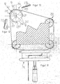
- FIGS. 9 to 15 comprises the one labeled 210 in FIG. 9
- Tensioning device a tape guide 212 - which the tension element represents - a housing 214, a clamping spindle 216 with a Pressure plate 218 and a spindle handle 220.
- the strap 222 is - for example, with its outer Noose - shown exposed around two workpieces 224 and 226.
- the strap When pulling the strap in the direction of arrow 223 in the simplest case, the strap is directly attached to the Workpieces 224 and 226.
- the spindle handle 220 On the spindle handle 220 is about Spindle 216 the pressure plate 218 from its zero position in a depression 213 led out and lies on the upper part 215 of the housing 214 - which forms the basic element - on.
- the pressure plate 218 clamps between itself and the upper one Part of the housing 214 the hinge sides 225 and 227 - or also Ends of the loop of the tension band called - one and makes additional clamping of the hinge sides with the tensioning process 225 and 227 superfluous.
- the band end 225 shown above in FIG. 9 is in one area 203 of housing 214 is held firmly and is in the other Direction around a deflection corner 230 through a housing opening 209 of the housing 214 led to the outside.
- the one shown below Band end 227 becomes an actuation side around a corner 233 led out of the housing 214.
- the housing 214 encloses the band guide 212 - or else Called tensile element -, narrow and results with lateral inner surfaces 234 or 235 an exact guide for the tape guide 212 during the clamping process.
- tape guide 212 can be on one of the two preferably in plastic executed parts 212 and 214 locking cams in general known execution can be provided.
- the band guide preferably has 212 - or also tension element called - arrow marks 236, which indicate an insertion of the Lightening strap, as shown in Fig. 9.
- Protrusions are provided on housing 214, preferably shown by cams 237 and 238, between which the strap 222 wound up when storing the tensioning device can be. In one slot 239, one end of the tension band can be be secured against independent winding.
- FIG. 10 is a top view of a tensioning device 210 shown without workpieces 224 and 226. The brought out Tensioning strap 222 is drawn cut off on both sides.
- the preferably provided reinforced wide tension band 222 is exactly between a longitudinal side 240 of the housing 214 and the tape guide 212, d. H. the tension element, guided, twisting and deflection is not possible.
- Band channels have a depth down to a stable lower part 241 of the tape guide 212, the bandwidth with something additional Match corresponds. This gives a band center or an actuation axis 205 an asymmetrical position that the Operated by hand when lying on a mat accommodates.
- the jig 210 is together with four suspended corner elements or clamping corners 250 and an inserted Workpiece 252 shown.
- An enlarged view 254 one of the four clamping corners 250 shows more clearly the constructive embodiment.
- a base body 256 is a hollow body, preferably with Self-suspension executed, in the present case as an open Cylinder with an opening 258 the corners and miters spring-loaded.
- the contact with workpiece 252 takes place with a rounding 260 which is suitable for all angles.
- a hollow body 256 In an interior of the base body designed as a hollow body 256 is space for workpiece tips for observation exposed, such as alternatively for lace Angle 261 or obtuse angle 262 in the area of the workpiece tips shown in Fig. 3.
- the also cylindrical outer shape of the clamping corner 254 leaves the tensioning strap 222 when tensioning without great friction losses slide along. It runs within a slot 264 on the section 265 visible on average along a line 12-12 (in Fig. 12).
- An insertion bevel 266 is provided on the opposite side. Two barbs 267 and 268 prevent accidental loss of the corners 254.
- a part 277 is rotatable on a cylinder surface with a section forming a diameter of 278 of the base body 256 clipped on.
- the clamping surface 274 has a transition radius 280 around it.
- the axis of rotation 279 of the pressure plate 277 corresponds to the asymmetrical arranged axis 205 in FIG. 10.
- a belt tensioner with a tensioning device is particularly advantageous or a tensioner 210, which also with two or more clamping corners 250 to protect the workpiece edges and for better sliding of the tensioning strap 222 around these edges is provided.
- clamping corners 250 or corner elements for edge or miter angles from 45 ° to 120 ° can be used continuously.
- these corners are 250 or corner elements subsequently captive on the strap 222 as required mountable.
- the clamping corner 250 in one piece in an open Cylinder shape is made.
- the Opening 258 - as shown in Fig. 11 - defined so that acute angle - designated by the reference numeral 261 - or also obtuse angles - designated by the reference number 262 - have space in the inner space or cavity of the hollow cylinder.
- the tape guide in a slot 264 which is open at the top, after has a shoulder 265 below and an insertion bevel 266 above and on both sides a cam 267 and 268 on the Cylinder is molded with an insertion slope 270 and a barbed approach 269 for securing of the strap.
- the approach 269 is lower than the slot outlet 272.
Landscapes
- Engineering & Computer Science (AREA)
- Mechanical Engineering (AREA)
- Clamps And Clips (AREA)
- Devices For Conveying Motion By Means Of Endless Flexible Members (AREA)
- Basic Packing Technique (AREA)
- Gripping Jigs, Holding Jigs, And Positioning Jigs (AREA)
- Finish Polishing, Edge Sharpening, And Grinding By Specific Grinding Devices (AREA)
- Forwarding And Storing Of Filamentary Material (AREA)
- General Details Of Gearings (AREA)
- Supports For Plants (AREA)
- Tires In General (AREA)
Description
- Fig. 1
- eine Gesamtdarstellung eines ersten Ausführungsbeispiels eines erfindungsgemäßen Bandspanners;
- Fig. 2
- eine Darstellung einer Spannvorrichtung des ersten Ausführungsbeispiels des erfindungsgemäßen Bandspanners mit teilweise aufgebrochenem Gehäuse;
- Fig. 3
- einen Schnitt durch einen Teilbereich der Spannvorrichtung längs Linie 3-3 in Fig. 2;
- Fig. 4
- eine Draufsicht auf die Spannvorrichtung in Richtung des Pfeils A in Fig. 2;
- Fig. 5
- eine Seitenansicht eines Eckelements ohne Druckteile;
- Fig. 6
- eine Seitenansicht des Eckelements mit Druckteilen;
- Fig. 7
- einen Schnitt längs Linie 7-7 in Fig. 6;
- Fig. 8
- eine Draufsicht auf das Eckelement in Richtung des Pfeils B in Fig. 5;
- Fig. 9
- eine Draufsicht auf ein zweites Ausführungsbeispiel eines erfindungsgemäßen Bandspanners;
- Fig. 10
- einen Schnitt längs Linie 10-10 in Fig. 9;
- Fig. 11
- eine vergrößerte Gesamtansicht des zweiten Ausführungsbeispiels des erfindungsgemäßen Bandspanners beim Spannen mit Eckelementen oder Spannecken;
- Fig. 12
- einen Schnitt längs Linie 12-12 in Fig. 11;
- Fig. 13
- einen Schnitt längs Linie 13-13 in Fig. 11;
- Fig. 14
- eine Seitenansicht eines zweiten Ausführungsbeispiels eines Eckelements;
- Fig. 15
- eine Draufsicht auf das Eckelement in Richtung des Pfeils C in Fig. 14;
- Fig. 16
- eine Seitenansicht eines zweiten Ausführungsbeispiels des Eckelements in Fig. 14 mit Druckteilen und
- Fig. 17
- eine Ansicht eines montierten Druckteils in Richtung des Pfeils D in Fig. 16.
Claims (34)
- Bandspanner mit einem Spannband (10, 222), welches zum Umschlingen eines oder mehrerer Werkstücke (14, 16, 224, 226) eine äußere Schlinge (12a) bildet, mit einer Spannvorrichtung (20, 210), relativ zu welcher ein erstes Ende (82, 225) der Schlinge (12a) festlegbar ist, mittels welcher die äußere Schlinge (12a) zum Spannen des Werkstücks oder der Werkstücke (14, 16, 224, 226) zusammenziehbar ist und welche ein an der Schlinge (12) mit einer Schlingendurchführung (30, 32; 209) abgestütztes Grundelement (28; 215) sowie ein Zugelement (24; 212) umfaßt, mit einer Verstellvorrichtung (26, 216), mittels welcher das Zugelement (24; 212) und das Grundelement (28; 215) relativ zueinander bewegbar sind, wobei bei einer Relativbewegung von Grundelement (28; 215) und Zugelement (24; 212) die äußere Schlinge (12a) unter Wirkung eines Flaschenzuges zusammenziehbar ist,
dadurch gekennzeichnet, daß die Schlinge (12) so zwischen dem Grundelement (28; 215) und dem Zugelement (24; 212) verläuft und an diesem angreift, daß bei einer Relativbewegung von Grundelement (28; 215) und Zugelement (24; 212) die äußere Schlinge (12a) unter Wirkung eines doppelten Flaschenzuges zusammenziehbar ist, daß die Größe der Schlinge (12) variierbar ist und daß ein zweites ende (92; 227) der Schlinge (12) an der Spannvorrichtung (20, 210) mittels einer Fixiereinrichtung (80) fixierbar ist. - Bandspanner nach Anspruch 1, dadurch gekennzeichnet, daß die Schlinge (12) mit einem ersten Abschnitt (82, 92; 225, 227) am Grundelement (28; 215) und mindestens zwei weiteren Abschnitten (84, 94) am Zugelement (24; 212) angreifend anliegt.
- Bandspanner nach Anspruch 2, dadurch gekennzeichnet, daß die Schlinge (12) zwei Schlaufen (84, 94) bildet, deren Umbiegungen die zwei weiteren Stellen bilden, mit denen die Schlinge (12) am Zugelement (24, 212) anliegt.
- Bandspanner nach einem der voranstehenden Ansprüche, dadurch gekennzeichnet, daß ein erstes Ende (82; 225) der Schlinge (12) an einer festgelegten Stelle des Spannbandes (10; 220) angeordnet ist und daß sich das Spannband (10; 220) über ein zweites Ende (92; 227) der Schlinge (12) hinaus als Spannbandreserve (96) fortsetzt und daß die Größe der Schlinge (12) durch Verkleinern oder Vergrößern der Spannbandreserve (96) variierbar ist.
- Bandspanner nach Anspruch 4, dadurch gekennzeichnet, daß das erste Ende (82; 225) und das zweite Ende (92; 227) der Schlinge (12) an der Spannvorrichtung (20, 210) angreifen.
- Bandspanner nach einem der voranstehenden Ansprüche, dadurch gekennzeichnet, daß das erste Ende (82; 225) und das zweite Ende (92; 227) in der Fixiereinrichtung (80) der Spannvorrichtung (20, 210) fixierbar sind.
- Bandspanner nach einem der voranstehenden Ansprüche, dadurch gekennzeichnet, daß die Fixiereinrichtung (80) kraftschlüssig auf das Spannband (10, 222) wirkt.
- Bandspanner nach einem der voranstehenden Ansprüche, dadurch gekennzeichnet, daß die Fixiereinrichtung (80) ein Fixierelement (136; 218) und ein Widerlager (140; 215) aufweist, zwischen welchen das Spannband (10; 222) einspannbar ist.
- Bandspanner nach einem der voranstehenden Ansprüche, dadurch gekennzeichnet, daß die Fixiereinrichtung (80) und die Verstellvorrichtung (26) gleichzeitig betätigbar sind.
- Bandspanner nach Anspruch 9, dadurch gekennzeichnet, daß das Fixierelement (136; 218) beim Bewegen des Grundelements (28; 215) und des Zugelements (24; 212) relativ zueinander durch die Verstellvorrichtung (26) betätigbar ist.
- Bandspanner nach Anspruch 10, dadurch gekennzeichnet, daß sich die Verstellvorrichtung (26) über die Fixiereinrichtung (80) am Grundelement (28; 215) abstützt.
- Bandspanner nach einem der voranstehenden Ansprüche, dadurch gekennzeichnet, daß das Zugelement (24; 212) zwei Zugkörper (46, 48; 230, 252) aufweist, von denen jeweils einer an einer der mindestens zwei Stellen (84, 94) auf die Schlinge (12) wirkt.
- Bandspanner nach Anspruch 12, dadurch gekennzeichnet, daß die Zugkörper (46, 48; 230, 232) beiderseits der Verstellvorrichtung (26) an dem Zugelement (24; 212) angeordnet sind.
- Bandspanner nach einem der voranstehenden Ansprüche, dadurch gekennzeichnet, daß die Verstellvorrichtung eine Spindel (130; 216) und eine auf der Spindel (130; 216) laufende Spindelmutter (44; 213) umfaßt.
- Bandspanner nach Anspruch 14, dadurch gekennzeichnet, daß die Spindelmutter (44; 213) am Zugelement (24; 212) gehalten ist und sich die Spindel (130; 216) an dem Grundelement (28; 215) abstützt.
- Bandspanner nach Anspruch 15, dadurch gekennzeichnet, daß sich die Spindel (130, 216) mit einem Spindelende (132) auf dem Fixierelement (136; 218) der Fixiereinrichtung (80) abstützt.
- Bandspanner nach einem der voranstehenden Ansprüche, dadurch gekennzeichnet, daß das Zugelement (24; 212) an einer mit dem Grundelement (28; 215) verbundenen Linearführung in Richtung auf dieses zu oder von diesem weg bewegbar, jedoch unverdrehbar geführt ist.
- Bandspanner nach Anspruch 17, dadurch gekennzeichnet, daß die Linearführung Teil eines Gehäuses (22; 214) der Spannvorrichtung (20, 210) ist.
- Bandspanner nach einem der voranstehenden Ansprüche, dadurch gekennzeichnet, daß das Grundelement (28; 215) ein Teil des Gehäuses (22; 214) ist.
- Bandspanner nach einem der voranstehenden Ansprüche, dadurch gekennzeichnet, daß das Grundelement (28; 215) zwei Führungsdurchbrüche (30, 32; 209) für jeweils ein Trum (12e, 12z) der Schlinge (12) aufweist.
- Bandspanner nach Anspruch 20, dadurch gekennzeichnet, daß die Führungsdurchbrüche (30, 32; 209) so gelegt sind, daß sich das jeweilige Trum (12e, 12z) der Schlinge (12) im Anschluß an die jeweils gebildete Schlaufe (84, 94) zwischen Grundelement (28; 215) und Zugelement (24; 212) durch den jeweiligen Führungsdurchbruch (30, 32; 209) hindurcherstreckt.
- Bandspanner nach einem der Ansprüche 4 bis 21, dadurch gekennzeichnet, daß die Spannvorrichtung (20; 210) einen Träger (98; 214) für die Spannbandreserve (96) aufweist.
- Bandspanner nach Anspruch 22, dadurch gekennzeichnet, daß der Träger (98; 214) als Wickelkörper für die Spannbandreserve (96) ausgebildet ist.
- Bandspanner nach einem der voranstehenden Ansprüche, dadurch gekennzeichnet, daß die äußere Schlinge (12a) zum Beaufschlagen der Werkstücke (14, 16; 252) mit Eckelementen (140; 250) versehen ist.
- Bandspanner nach Anspruch 24, dadurch gekennzeichnet, daß die Eckelemente (140; 250) unverlierbar am Spannband (10, 222) fixierbar sind.
- Bandspanner nach Anspruch 25, dadurch gekennzeichnet, daß die Eckelemente (140; 250) mit am Spannband (210; 222) angreifenden Halteelementen (188, 190) versehen sind.
- Bandspanner nach Anspruch 26, dadurch gekennzeichnet, daß die Halteelemente (188, 190) so ausgebildet sind, daß das Spannband (10) quer zu seiner Längsrichtung in eine durch die Halteelemente (188, 190) fixierte Stellung an den Eckelementen (140) einschiebbar ist.
- Bandspanner nach Anspruch 26 oder 27, dadurch gekennzeichnet, daß die Halteelemente (188, 190) das Spannband (10) von einer Seitenkante her auf einer Flachseite übergreifen.
- Bandspanner nach einem der Ansprüche 26 bis 28, dadurch gekennzeichnet, daß das Spannband (10) gegen ein Herausgleiten aus dem jeweiligen Halteelement (188, 190) gesichert ist.
- Bandspanner nach einem der Ansprüche 24 bis 29, dadurch gekennzeichnet, daß die Eckelemente (140; 250) einen Hohlraum (148) U-förmig umgreifen und endseitig der Schenkel des U Drucknasen (144, 146) aufweisen, mit welchen die Eckelemente (140; 250) auf die Werkstücke (14, 16; 252) wirken.
- Bandspanner nach Anspruch 30, dadurch gekennzeichnet, daß die Drucknasen (144, 146) auf gegenüberliegenden Seiten der Ecken der Werkstücke (14, 16) anliegen.
- Bandspanner nach Anspruch 30 oder 31, dadurch gekennzeichnet, daß die Eckelemente (140, 250) im Bereich ihrer Drucknasen (144, 146) mit schwenkbar an diesen gelagerten Druckteilen (148, 150) versehen sind, welche ihrerseits Druckflächen (152; 274) aufweisen, mit welchen die Druckteile (148, 150) auf das Werkstück (14, 16; 252) wirken.
- Bandspanner nach Anspruch 32, dadurch gekennzeichnet, daß die Druckteile (148, 150) mit ebenen oder leicht gewölbten Druckflächen (152; 274) versehen sind.
- Bandspanner nach einem der Ansprüche 24 bis 33, dadurch gekennzeichnet, daß die Eckelemente (140; 250) so ausgebildet sind, daß das Spannband (10; 222) vollflächig auf diesen aufliegt.
Priority Applications (1)
| Application Number | Priority Date | Filing Date | Title |
|---|---|---|---|
| AU45893/96A AU716968B2 (en) | 1995-03-04 | 1996-03-06 | Strap clamping device |
Applications Claiming Priority (2)
| Application Number | Priority Date | Filing Date | Title |
|---|---|---|---|
| DE19507699A DE19507699A1 (de) | 1995-03-04 | 1995-03-04 | Bandspanner |
| DE19507699 | 1995-03-04 |
Publications (2)
| Publication Number | Publication Date |
|---|---|
| EP0730932A1 EP0730932A1 (de) | 1996-09-11 |
| EP0730932B1 true EP0730932B1 (de) | 2001-07-11 |
Family
ID=7755706
Family Applications (1)
| Application Number | Title | Priority Date | Filing Date |
|---|---|---|---|
| EP96103026A Expired - Lifetime EP0730932B1 (de) | 1995-03-04 | 1996-02-29 | Bandspanner |
Country Status (7)
| Country | Link |
|---|---|
| US (1) | US5918866A (de) |
| EP (1) | EP0730932B1 (de) |
| JP (1) | JPH10329043A (de) |
| AT (1) | ATE202962T1 (de) |
| CA (1) | CA2170697C (de) |
| DE (2) | DE19507699A1 (de) |
| DK (1) | DK0730932T3 (de) |
Cited By (2)
| Publication number | Priority date | Publication date | Assignee | Title |
|---|---|---|---|---|
| DE10349229B4 (de) * | 2003-10-23 | 2013-05-29 | Wolfcraft Gmbh | Bandspanner und zugehörige Spannbacken |
| CN104044096A (zh) * | 2014-06-09 | 2014-09-17 | 首钢总公司 | 辉光放电光谱仪用自动夹样机构及方法 |
Families Citing this family (9)
| Publication number | Priority date | Publication date | Assignee | Title |
|---|---|---|---|---|
| US6405437B1 (en) * | 1997-09-17 | 2002-06-18 | Arvinmeritor, Inc. | Apparatus and method for encasing an object in a case |
| US6601616B1 (en) | 2001-10-17 | 2003-08-05 | Challenger Manufacturing Consultants, Inc. | Powered clamp application tool |
| US7048015B2 (en) * | 2001-10-17 | 2006-05-23 | Challenger Manufacturing Consultants, Inc. | Powered clamp application tool |
| US7419148B1 (en) * | 2004-10-19 | 2008-09-02 | Lee Valley Tools, Ltd. | Variable angle flexible band clamp corner |
| US7950636B2 (en) * | 2007-04-19 | 2011-05-31 | Rockler Companies, Inc. | Miter joint clamp |
| US20090293168A1 (en) * | 2008-05-29 | 2009-12-03 | Lugtu Alma M | Body covering and methods therefor |
| EP2228170A1 (de) * | 2009-03-12 | 2010-09-15 | Siemens Aktiengesellschaft | Werkstückspannvorrichtung mit Spanngurt |
| DE102010015345A1 (de) | 2010-04-17 | 2011-10-20 | Horst Klimach | Bandzwinge |
| US10232451B2 (en) * | 2017-02-08 | 2019-03-19 | Brandon T. Barrett | Fastener for securing and cutting an object and methods relating thereto |
Family Cites Families (18)
| Publication number | Priority date | Publication date | Assignee | Title |
|---|---|---|---|---|
| DE181133C (de) * | 1900-01-01 | |||
| US442934A (en) * | 1890-12-16 | Clamp | ||
| US633657A (en) * | 1898-05-19 | 1899-09-26 | Barthel Mueller | Clamping appliance for frames with glued mitered joints. |
| US720816A (en) * | 1902-03-05 | 1903-02-17 | Eduard C Karl | Clamp. |
| US891121A (en) * | 1907-11-20 | 1908-06-16 | Henry Wichers | Clamp. |
| US1053556A (en) * | 1912-03-18 | 1913-02-18 | Handy Mfg Company | Corner-clamping appliance. |
| US1770763A (en) * | 1928-02-03 | 1930-07-15 | Pittsburgh Des Moines Company | Clamp |
| CH152655A (de) * | 1931-03-02 | 1932-02-15 | Ueltschi Fritz | Einspann-Vorrichtung. |
| FR717381A (fr) * | 1931-05-16 | 1932-01-07 | équerre-tendeur formant serre-joints pour le collage des cadres | |
| US2696232A (en) * | 1951-02-05 | 1954-12-07 | Wintercorn Andrew F | Adjustable plural joint miter clamp |
| GB1006056A (en) * | 1963-07-17 | 1965-09-29 | John Galpin | Improvements in and relating to clamps or cramps |
| US3584860A (en) * | 1968-07-05 | 1971-06-15 | James Edwin Ervin | Belt pipe vise |
| US4171799A (en) * | 1978-06-26 | 1979-10-23 | Elko George A | Frame assembly jig |
| CH643175A5 (fr) * | 1981-03-05 | 1984-05-30 | Gueissaz Andre & Cie Sa | Appareil d'assemblage a serre-joint quadrangulaire pour la confection de cadres ou de panneaux. |
| US4560153A (en) * | 1984-04-20 | 1985-12-24 | Han David C | Fixing tool for square frame |
| DE8511115U1 (de) * | 1985-04-16 | 1985-09-19 | Fa. Friedrich Küpper, 5531 Berlingen | Vorrichtung zum Spannen von Bilderrahmen |
| IT215665Z2 (it) * | 1988-06-16 | 1990-10-22 | Valex Int | Struttura di morsetto regolabile particolarmente per cornici e telai. |
| US5161789A (en) * | 1991-08-27 | 1992-11-10 | Rogers Winston L | Universal clamping device |
-
1995
- 1995-03-04 DE DE19507699A patent/DE19507699A1/de not_active Withdrawn
-
1996
- 1996-02-29 AT AT96103026T patent/ATE202962T1/de not_active IP Right Cessation
- 1996-02-29 CA CA002170697A patent/CA2170697C/en not_active Expired - Fee Related
- 1996-02-29 EP EP96103026A patent/EP0730932B1/de not_active Expired - Lifetime
- 1996-02-29 DK DK96103026T patent/DK0730932T3/da active
- 1996-02-29 DE DE59607246T patent/DE59607246D1/de not_active Expired - Lifetime
- 1996-03-04 JP JP8075323A patent/JPH10329043A/ja active Pending
-
1997
- 1997-09-11 US US08/927,999 patent/US5918866A/en not_active Expired - Lifetime
Cited By (3)
| Publication number | Priority date | Publication date | Assignee | Title |
|---|---|---|---|---|
| DE10349229B4 (de) * | 2003-10-23 | 2013-05-29 | Wolfcraft Gmbh | Bandspanner und zugehörige Spannbacken |
| CN104044096A (zh) * | 2014-06-09 | 2014-09-17 | 首钢总公司 | 辉光放电光谱仪用自动夹样机构及方法 |
| CN104044096B (zh) * | 2014-06-09 | 2016-06-29 | 首钢总公司 | 辉光放电光谱仪用自动夹样机构及方法 |
Also Published As
| Publication number | Publication date |
|---|---|
| DE59607246D1 (de) | 2001-08-16 |
| CA2170697C (en) | 2008-03-11 |
| DE19507699A1 (de) | 1996-09-05 |
| JPH10329043A (ja) | 1998-12-15 |
| ATE202962T1 (de) | 2001-07-15 |
| DK0730932T3 (da) | 2001-10-15 |
| US5918866A (en) | 1999-07-06 |
| CA2170697A1 (en) | 1996-09-05 |
| EP0730932A1 (de) | 1996-09-11 |
Similar Documents
| Publication | Publication Date | Title |
|---|---|---|
| DE2845227C2 (de) | Riemen- oder Bandspannvorrichtung | |
| DE102005031735B3 (de) | Spannratsche zum Spannen und Halten von Spannmitteln | |
| EP0730932B1 (de) | Bandspanner | |
| EP0085965A1 (de) | Spannschloss für Gurtbänder | |
| DE4143411C2 (de) | Sicherheitsbindung | |
| DE102014106227A1 (de) | Kabelverriegelungssystem | |
| EP0281836B1 (de) | Gurtanschlussvorrichtung | |
| DE19643321B4 (de) | Kettenspanner mit Schraubenfeder | |
| EP1086656A2 (de) | Chirurgisches Cerclageband | |
| EP0504557B1 (de) | Spann- und Zurrvorrichtung für Zurrstränge | |
| DE2733238C2 (de) | ||
| EP1839915A2 (de) | Spannvorrichtung für eine Gleitschutzkette | |
| DE3102658A1 (de) | Geraet zum bespannen von tennisschlaegern oder dergleichen | |
| DE1435219B2 (de) | Klöppel für Flechtmaschinen, insbesondere Schlauchumflechtungsmaschinen | |
| DE20115647U1 (de) | Linearpositionierer mit einer Spann- und Justagevorrichtung | |
| DE1750244C3 (de) | Vorrichtung zum Einstellen eines Spieles zwischen zwei Körpern | |
| EP0217151B1 (de) | Klemm-Spannvorrichtung für Seile, Bänder, Gurte o.dgl. | |
| DE202007012284U1 (de) | Chirurgischer Retraktor | |
| EP3109140A1 (de) | Halterung für ein zweirad-zubehör | |
| DE19839245C1 (de) | Spannvorrichtung für Gurte und dergleichen | |
| EP0641940B1 (de) | Verbindungseinrichtung für Profilteile | |
| DE2714163A1 (de) | Einstellvorrichtung fuer getriebebandspanner | |
| DE20309947U1 (de) | Ständer zum Aufspannen von stabförmigen Teilen, insbesondere von Christbäumen | |
| DE20309948U1 (de) | Ständer zum Aufspannen von stabförmigen Teilen, insbesondere von Christbäumen | |
| DE102007039436B4 (de) | Spannwinde |
Legal Events
| Date | Code | Title | Description |
|---|---|---|---|
| PUAI | Public reference made under article 153(3) epc to a published international application that has entered the european phase |
Free format text: ORIGINAL CODE: 0009012 |
|
| AK | Designated contracting states |
Kind code of ref document: A1 Designated state(s): AT BE CH DE DK FR IT LI NL |
|
| 17P | Request for examination filed |
Effective date: 19970124 |
|
| 17Q | First examination report despatched |
Effective date: 19970924 |
|
| GRAG | Despatch of communication of intention to grant |
Free format text: ORIGINAL CODE: EPIDOS AGRA |
|
| GRAG | Despatch of communication of intention to grant |
Free format text: ORIGINAL CODE: EPIDOS AGRA |
|
| GRAG | Despatch of communication of intention to grant |
Free format text: ORIGINAL CODE: EPIDOS AGRA |
|
| GRAH | Despatch of communication of intention to grant a patent |
Free format text: ORIGINAL CODE: EPIDOS IGRA |
|
| GRAH | Despatch of communication of intention to grant a patent |
Free format text: ORIGINAL CODE: EPIDOS IGRA |
|
| GRAA | (expected) grant |
Free format text: ORIGINAL CODE: 0009210 |
|
| AK | Designated contracting states |
Kind code of ref document: B1 Designated state(s): AT BE CH DE DK FR IT LI NL |
|
| PG25 | Lapsed in a contracting state [announced via postgrant information from national office to epo] |
Ref country code: FR Free format text: LAPSE BECAUSE OF FAILURE TO SUBMIT A TRANSLATION OF THE DESCRIPTION OR TO PAY THE FEE WITHIN THE PRESCRIBED TIME-LIMIT Effective date: 20010711 |
|
| REF | Corresponds to: |
Ref document number: 202962 Country of ref document: AT Date of ref document: 20010715 Kind code of ref document: T |
|
| REG | Reference to a national code |
Ref country code: CH Ref legal event code: EP |
|
| REF | Corresponds to: |
Ref document number: 59607246 Country of ref document: DE Date of ref document: 20010816 |
|
| REG | Reference to a national code |
Ref country code: CH Ref legal event code: NV Representative=s name: KIRKER & CIE SA |
|
| ITF | It: translation for a ep patent filed | ||
| REG | Reference to a national code |
Ref country code: DK Ref legal event code: T3 |
|
| EN | Fr: translation not filed | ||
| PLBE | No opposition filed within time limit |
Free format text: ORIGINAL CODE: 0009261 |
|
| STAA | Information on the status of an ep patent application or granted ep patent |
Free format text: STATUS: NO OPPOSITION FILED WITHIN TIME LIMIT |
|
| 26N | No opposition filed | ||
| PGFP | Annual fee paid to national office [announced via postgrant information from national office to epo] |
Ref country code: DK Payment date: 20080215 Year of fee payment: 13 Ref country code: CH Payment date: 20080226 Year of fee payment: 13 |
|
| PGFP | Annual fee paid to national office [announced via postgrant information from national office to epo] |
Ref country code: NL Payment date: 20080229 Year of fee payment: 13 Ref country code: IT Payment date: 20080124 Year of fee payment: 13 |
|
| PGFP | Annual fee paid to national office [announced via postgrant information from national office to epo] |
Ref country code: AT Payment date: 20080211 Year of fee payment: 13 |
|
| PGFP | Annual fee paid to national office [announced via postgrant information from national office to epo] |
Ref country code: BE Payment date: 20080205 Year of fee payment: 13 |
|
| BERE | Be: lapsed |
Owner name: *BESSEY & SOHN G.M.B.H. & CO. Effective date: 20090228 |
|
| REG | Reference to a national code |
Ref country code: CH Ref legal event code: PL |
|
| REG | Reference to a national code |
Ref country code: DK Ref legal event code: EBP |
|
| PG25 | Lapsed in a contracting state [announced via postgrant information from national office to epo] |
Ref country code: LI Free format text: LAPSE BECAUSE OF NON-PAYMENT OF DUE FEES Effective date: 20090228 Ref country code: CH Free format text: LAPSE BECAUSE OF NON-PAYMENT OF DUE FEES Effective date: 20090228 Ref country code: AT Free format text: LAPSE BECAUSE OF NON-PAYMENT OF DUE FEES Effective date: 20090228 |
|
| NLV4 | Nl: lapsed or anulled due to non-payment of the annual fee |
Effective date: 20090901 |
|
| PG25 | Lapsed in a contracting state [announced via postgrant information from national office to epo] |
Ref country code: NL Free format text: LAPSE BECAUSE OF NON-PAYMENT OF DUE FEES Effective date: 20090901 |
|
| PG25 | Lapsed in a contracting state [announced via postgrant information from national office to epo] |
Ref country code: BE Free format text: LAPSE BECAUSE OF NON-PAYMENT OF DUE FEES Effective date: 20090228 |
|
| PG25 | Lapsed in a contracting state [announced via postgrant information from national office to epo] |
Ref country code: DK Free format text: LAPSE BECAUSE OF NON-PAYMENT OF DUE FEES Effective date: 20090831 |
|
| PG25 | Lapsed in a contracting state [announced via postgrant information from national office to epo] |
Ref country code: IT Free format text: LAPSE BECAUSE OF NON-PAYMENT OF DUE FEES Effective date: 20090228 |
|
| REG | Reference to a national code |
Ref country code: DE Ref legal event code: R082 Ref document number: 59607246 Country of ref document: DE Representative=s name: HOEGER, STELLRECHT & PARTNER PATENTANWAELTE MB, DE |
|
| PGFP | Annual fee paid to national office [announced via postgrant information from national office to epo] |
Ref country code: DE Payment date: 20150327 Year of fee payment: 20 |
|
| REG | Reference to a national code |
Ref country code: DE Ref legal event code: R071 Ref document number: 59607246 Country of ref document: DE |