EP0731055A1 - Kapselmaschine - Google Patents
Kapselmaschine Download PDFInfo
- Publication number
- EP0731055A1 EP0731055A1 EP96301492A EP96301492A EP0731055A1 EP 0731055 A1 EP0731055 A1 EP 0731055A1 EP 96301492 A EP96301492 A EP 96301492A EP 96301492 A EP96301492 A EP 96301492A EP 0731055 A1 EP0731055 A1 EP 0731055A1
- Authority
- EP
- European Patent Office
- Prior art keywords
- cap
- chute
- container
- guide means
- stops
- Prior art date
- Legal status (The legal status is an assumption and is not a legal conclusion. Google has not performed a legal analysis and makes no representation as to the accuracy of the status listed.)
- Granted
Links
- 238000000034 method Methods 0.000 claims description 9
- 230000013011 mating Effects 0.000 claims description 3
- 238000010792 warming Methods 0.000 claims description 2
- 239000011521 glass Substances 0.000 abstract description 6
- 238000007493 shaping process Methods 0.000 description 3
- 239000004743 Polypropylene Substances 0.000 description 2
- -1 polypropylene Polymers 0.000 description 2
- 229920001155 polypropylene Polymers 0.000 description 2
- 230000003542 behavioural effect Effects 0.000 description 1
- 230000005484 gravity Effects 0.000 description 1
- 238000004519 manufacturing process Methods 0.000 description 1
- 239000004033 plastic Substances 0.000 description 1
- 230000002028 premature Effects 0.000 description 1
- 230000000284 resting effect Effects 0.000 description 1
- 238000003079 width control Methods 0.000 description 1
Images
Classifications
-
- B—PERFORMING OPERATIONS; TRANSPORTING
- B67—OPENING, CLOSING OR CLEANING BOTTLES, JARS OR SIMILAR CONTAINERS; LIQUID HANDLING
- B67B—APPLYING CLOSURE MEMBERS TO BOTTLES JARS, OR SIMILAR CONTAINERS; OPENING CLOSED CONTAINERS
- B67B3/00—Closing bottles, jars or similar containers by applying caps
- B67B3/02—Closing bottles, jars or similar containers by applying caps by applying flanged caps, e.g. crown caps, and securing by deformation of flanges
- B67B3/06—Feeding caps to capping heads
Definitions
- This invention relates to a capping apparatus and a method of capping.
- it relates to an apparatus for applying caps, such as press-on, twist-off caps (PT-PLUS or PT+ (trade marks), having a tamper evident ring to containers such as glass jars.
- a capping apparatus includes a cap chute fitted above and at an angle to a horizontal conveyor, along which containers pass during the capping process.
- PT plus caps and PT (trade mark) caps without tamper evident rings are generally applied to glass jars by a cap chute in which a series of caps pass down a delivery portion of the cap chute to a cap pick-up point, where each cap is collected by a respective jar.
- the jars pass along a horizontal conveyor which forms part of the capping apparatus beneath the cap chute at a speed of 200 to 800 caps per minute, so that it is particularly important that a cap is immediately available for collection and that the cap is in the correct position for mating with the top of the container or jar.
- PT+ caps suffer from a number of problems which differ from those found with PT closures, since the presence of a tamper evident ring aggravates an already difficult capping procedure and it is therefore not possible to use existing cap chutes.
- the polypropylene tamper evident ring is preheated by high pressure steam, so that the ring becomes elastically pliable and is able to be forced down and expanded over the mouth of a rigid container.
- the soft polypropylene can thus be deformed by the container if the ring does not engage the container correctly.
- the cap may be tilted over the leading edge of the container.
- This tilting may be corrected by a "shoe” device which also forms part of the capper and which applies a load to the top of the cap/jar as it emerges from the capper. The shoe forces the cap back into the horizontal position but, as this is done, the soft tamper evident ring "crumples" and in extreme cases may become folded back onto itself and folded between the inside of the cap itself and the outer edge of the jar.
- a cap may become stuck or obstructed in the cap chute in some way, so that there is a delay in the cap reaching the correct position for collection by a container such as a glass jar. If a jar arrives before the cap, then the jar will not collect a cap as it passes towards the end of the cap chute. In this situation, the trailing edge of the jar may engage with the front of a cap, so that the rim of the jar pushes into the tamper evident ring. Since the ring is soft, the rim of the jar deforms the ring and may become embedded in the ring and pull the cap out of the cap chute. As a result, the next ring is also in an incorrect position and the situation may perpetuate itself with a series of rings each overlapping two successive containers when the containers are close to each other. This is known as an "avalanche" situation.
- a capping apparatus for a cap having a tamper evident ring connected to a hem at the base of the cap including:
- the apparatus further includes at least one stop for preventing a cap from falling out of the cap chute outlet.
- Each stop is preferably taller than in prior art cappers, so that it is possible for the leading cap to rise upwards before it passes over the top of the stop(s).
- the ability to rise up on the stops is useful if the "avalanche" situation described above arises, in which the rim of a container becomes embedded in part of the tamper evident ring on a PT+ cap, ie misaligned. If the cap can rise up the stops, the cap can free itself from the container rim and will then be forced back down onto the delivery part of the chute by holding means.
- the tamper evident ring on the PT+ cap causes the cap to sit higher on the chute outlet so that higher stops are required than for a PT cap.
- the extra height given to the PT+ cap by the tamper evident ring can also cause the cap to lift over one of the stops and be forced out of the chute by the weight of further caps behind the leading caps so that a cascade of caps may then fall onto the containers on the conveyor below.
- Capping processes are high speed operations, generally applying caps at a rate of up to 800 caps/min. It is therefore critical that no cascade of caps occurs, since the capping process would have to be halted in order to clear the caps from the container conveyor.
- conventional PT cappers the dimensions of the chute itself are therefore carefully controlled. The sides of the chute delivery part are adjusted to a width marginally wider than the width of the caps and a plate or block is lowered to limit the head space over the caps in the chute. A minimum clearance is thus allowed in conventional chutes which will still allow clear passage of the caps.
- the dimensions must not allow lateral movement or undue twisting of the caps in the chute but must not be reduced to such an extent that the caps stick within the chute delivery part itself. In the present invention, however, such tight tolerances of the chute are not required, since the extended guide means, stops and holding means eliminate the need for control within the chute itself.
- a further feature of know PT cappers is a hold-down and a slide block.
- the hold-down is spring-loaded and is intended to press down on the cap so as to prevent it from inadvertently twisting over the stops and out of the chute.
- the hold-down of known PT cappers is only partially successful in this since it only extends over a central portion of the cap, so that pivoting about the hold-down is still possible.
- the stops are usually extended upwardly to prevent the cap from falling out of the chute and the hold down is designed to prevent pivoting over the stops as described below.
- the slide block takes over from the hold down as a container engages with the leading cap and starts to lift it over the stops.
- the slide block is also spring-loaded and presses down on the cap and jar so that the cap is held in the correct position on the jar. Again, however, in the prior art, the slide block only extends over a central portion of the cap, so that pivoting is possible.
- the holding means may typically comprise a hold-down for holding the cap onto the container as it collects the cap and lifts the cap over the stop or stops.
- the hold-down preferably extends laterally across substantially the whole of the cap, so that pivoting of the cap is prevented.
- the holding means may further comprise means for biasing the cap into mating engagement with the container mouth.
- the biasing means may also act as a further guide, such as a slide block, so that the cap slides between the slide block and the guide means until it is generally substantially parallel with the container mouth.
- the biasing means preferably extends laterally across substantially the whole width of the cap so that control of the cap is still carefully controlled once the cap passes beyond the hold-down and support section.
- the guide means may include the stop or stops and may comprise a support section and one or more guide rails.
- the cap rests on a pair of supports and against a pair of stops, one on each side of the cap which prevent the cap from falling out of the cap chute. Once a container lifts the cap over the stops, the cap rests on a pair of guide rails and is biased against the rails by the slide block.
- the capping apparatus thus maintains control of the cap right up to the point when it is seated correctly over the container mouth.
- Such control is particularly valuable when used with PT+ caps, where a concentric alignment of the cap and tamper evident ring on a container is required as the slide block biases the cap onto the jar.
- the pair of guide rails in the present invention support a hem at the base of the cap.
- the cap may be a PT+ cap, in which case the cap has a more pronounced hem than that of a PT cap and the guide rails may be profiled to support the hem at the base of the cap.
- a tamper evident ring which is connected to the hem may then extend inside the guide rails.
- the profiling of the guide rails is particularly important to enable the cap to move from its inclined position in the cap chute to a generally horizontal position, concentric with the container.
- the PT+ cap rests with its tamper evident ring on the support section of the guide means and control of the cap position may also comprise shaping of individual components so that the softened ring passes within the guide rails when lifted over the stops and the biasing means does not cause any direct pressure to be transmitted to the ring which might otherwise cause the ring to be distorted.
- the shaping of individual components may include scalloped-shaped stops.
- This shape additionally has the advantage that scuffing of the cap is avoided.
- Profiling of the stops may also be provided to facilitate upward and forward movement of the cap over the stops as it is collected by a container.
- the hold-down may usually include wings.
- the provision of a winged shape prevents the cap from twisting over the stops prematurely.
- the slide block is also provided with wings which again prevents twisting or pivoting of the cap.
- the slide block may include a scalloped back, so that the leading edge of the cap does not catch on the slide block. This is particularly important for a PT+ cap, since if a container attempts to collect the cap it can sometimes be prevented from doing so if the cap were caught on the slide block. However, the container would still engage the tamper evident ring and rip it off the cap body itself as the container is moved forward by the conveyor on which it sits.
- the preferred shaping of these individual components serves to control the cap position precisely so as to ensure a clean pick-up by a container.
- the efficiency of such a design results in the width of the guide chute ceasing to be as critical as in capping apparati of the prior art.
- the profiling of various components according to the present invention avoids the need for control of the guide chute width.
- the apparatus may include a chute having a fixed width which may allow typically as much as between 2mm and 3mm either side of the caps because control at the end of the chute is so carefully controlled. Whilst this means a different chute for different width caps, there are usually only two dedicated chutes required - one for 51mm caps and a second for 40mm caps. Both dedicated chutes are simplified over prior art chutes since there is no requirement for the provision of adjusters for altering the chute width.
- the chutes may also need to differ to cope with the difference in behavioural characteristics between caps of varying widths.
- a 51mm cap has a greater amount of plastic available for stretching its tamper evident ring over the mouth of a glass jar than does a 40mm cap.
- the 51mm cap is thus more flexible in its application to the jar since the ring does not need to stretch as much as a 40mm cap in the short time available for application.
- a method of applying a cap to a container comprising:
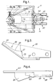
- FIGS. 1 and 2 there is shown a capping apparatus 5 suitable for applying a series of PT+ caps to glass jars which pass below the capper in the direction indicated by the double arrow in figure 2.
- a series of caps enters the passes along a chute 10 within the apparatus to a pick-up point 15 at the opposite end of the chute.
- High pressure steam is passed down the chute so that a tamper evident ring fixed to a hem at the base of the PT+ cap is softened ready for passing over beading or other engagement features around the mouth of a container.
- the pick-up point 15 comprises a region of the capping apparatus which is extended beyond the chute 10 by a pair of guide extensions 20.
- Each extension has a stop 22, a support rail 24 and a guide rail 26.
- Above the guide extensions are provided a winged hold down 30 (see figure 2) and a winged slide block 35 which are spring loaded to provide downward forces.
- the apparatus further includes height adjustment components 40 and, optionally, width adjustment components 45 which provide adjustment of the chute dimensions for different sizes of cap.
- width adjustment components are omitted as these are not required in the present invention. It would also be possible to omit the height adjustment components 40, if the height of the chute is preset during manufacture to the height of the caps with which the chute is to be used.
- the capping apparatus is generally operated at an angle of about 40° to the horizontal, so that caps descend along the chute to the pick-up point under the action of gravity.
- the two stops 22 prevent the leading cap from moving forward from its position on the support rails 24 pending pick-up by the next jar.
- This location on the support rails is assisted by the hold-down 30 which is situated over the leading cap which is on the support rails and sitting against the stops.
- the hold-down is spaced slightly from the top of the cap so that no downward pressure is exerted on the cap whilst it is resting on its tamper evident ring at the stop position. If the cap is lifted, however, the hold-down acts directly on the cap. There is thus never any sandwiching of the cap and tamper evident ring which would exert pressure on the tamper evident ring.
- the PT+ cap simply rests on its tamper evident ring on the support rails, ready for collection by the next container.
- the hold-down is generally bevelled from rear to front so that each cap is guided towards the outlet of the apparatus freely and easily once the cap is collected by the container.
- the leading cap is thus maintained in position by the stops and hold-down but the weight of the caps behind has been known in previous PT cappers to cause the leading cap to twist over one or both of the stops, thus allowing it to fall onto the jar conveyor below the capper. This problem has been substantially eliminated by the stop height and winged hold down.
- the leading cap When the leading cap is picked up by a jar, it is carried beyond the stops but the hem of the cap instead of the tamper evident ring then rests on the guide rails 26.
- the stops are therefore profiled so that the hem of the cap passes smoothly over the stops and onto the guide rails.
- the tamper evident ring of the cap meanwhile passes within these guide rails. The profiling of the individual components thus avoids damage to the tamper evident ring, which is softened so that it is capable of passing over screw threads on the jar, for example.
- a slide block 35 takes over from the hold-down as the cap passes along the guide rails and exerts a downward force on the cap to help maintain the cap in the correct substantially horizontal position between the slide block and the guide rails as it engages the jar.
- the slide block is also provided with wings in the present invention. The cap is thus still prevented from twisting by the slide block and guide rail combination, even though the cap is being carried by a jar.
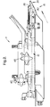
- a typical guide extension 20 is shown in more detail in figures 3 and 4. This aspect shows the inside of the guide extension which comprises the stop 22, support rail 24 and guide rail 26.
- the guide extension is bolted onto the end of the delivery part of the cap chute 10 as seen in figures 1 and 2 so that the support rail 24 is in the same plane as the base of the delivery part 10.
- the PT+ caps thus rests on its tamper evident ring on the support rails 24 as the cap exits the delivery part 10 and is prevented from further forward motion by the stops 22.
- the cap As the cap is picked up by a jar, it lifts the cap over the stops 22 against the downward force of the hold-down until the hem of the cap rests on the guide rails 26.
- the guide rails are spaced further apart than the tamper ring diameter, so that only the hem rests on the guide rails.
- the stops are profiled at their front edges 27 as is best seen in figure 4, so the cap can be smoothly transferred onto the guide rails from the support rails, with the hem of the cap moving onto the guide rails as the cap is lifted over the stops and off the support rails. Meanwhile, the tamper evident ring passes within the guide rails so that no direct pressure is exerted on it.
- the guide rails curve at 28 to allow the cap to be gradually transferred from its initial inclined position towards the horizontal position in which it will be forced onto the jar.
- a final portion 29 of the guide rail which is parallel to the plane of the top of the jar and conveyor, ie roughly horizontal, ensures that the cap is held firmly between the slide block and this planar portion 29 as the jar is forced into the cap.
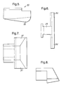
- Figures 5 and 6 show the hold-down and how it is shaped so as better to control the positioning of the cap.
- Figure 4 shows the profile of the hold-down which, in use, would engage a cap passing from left to right.
- the deepest portion 32 of the hold-down is just clear of the top of the cap and forward of its centre. The hold-down only contacts the cap when it is lifted up the stops.
- any tendency of the cap to lift upwards due to the weight of caps impinging on the rear of the cap is controlled by the bevelled shape of the hold-down which guides the cap back towards the correct position on the support rails behind the stops.
- the cap is thus not held firmly between the hold-down and support rails which might damage the tamper evident ring but unwanted movement of the cap over the stops is prevented by the hold-down if the cap is lifted at all by the weight of caps behind it in the delivery part of the cap chute, for example.
- the slide block (see figures 7 and 8) is also provided with wings 37.
- the winged portions are angled so as to be parallel with the planar portion of the guide rails, thus controlling the cap effectively as described above.
- cap position is controlled very carefully by the various elements of the extended capping apparatus whilst pick-up by a jar is taking place.
- the softened tamper evident ring of PT+ cap is maintained free of the guide rails as the jar is forced into the cap, so that crumpling of the ring is effectively avoided. Crumpling of the tamper evident ring is also avoided by the provision of the guide extensions, in particular the guide rails themselves, which guide the cap from the incline to the horizontal so that the cap is coaxial with the jar when it is forced down onto the jar. Any inclination of the cap would cause the tamper evident ring to be distorted.
- the cap position is controlled so well by the elements of the present invention, that adjustment of the width of the delivery part of the cap chute 10 is no longer required.
- the chute dimensions have been adjusted so as to give minimum clearance for the caps as they pass along the delivery part of the chute. This prevented lateral movement or undue twisting of the caps within the delivery part itself.
- the control of the present invention only the adjustment of the height of the delivery part is needed and it is possible to use fixed width dedicated chutes for each of the standard sizes of PT+ caps.
- the control of the cap orientation ensures that the cap does not tilt over the mouth of the container when it is picked up which would otherwise result in the tamper evident ring being distorted and even folded back on itself when pressed down on the container by a "shoe" which loads the cap once it leaves the cap chute part of the capping apparatus.
- the shoe will be positioned nearer to the cap chute than in prior art systems so that control is still maintained once the cap leaves the control of the slide block.
- the delivery part of the cap chute can be a fixed width in which caps can move freely, there is no danger of caps becoming stuck in the chute itself. Thus there is no delay in the cap reaching the correct position for collection by the container with the self-perpetuating avalanche problems of caps overlapping a pair of containers when the tamper evident rings are embedded in the edge of the container mouth as described above.
Landscapes
- Engineering & Computer Science (AREA)
- Mechanical Engineering (AREA)
- Sealing Of Jars (AREA)
- Closing Of Containers (AREA)
- Seal Device For Vehicle (AREA)
- Medicinal Preparation (AREA)
- Helmets And Other Head Coverings (AREA)
- Pipe Accessories (AREA)
Applications Claiming Priority (2)
| Application Number | Priority Date | Filing Date | Title |
|---|---|---|---|
| GBGB9504778.3A GB9504778D0 (en) | 1995-03-09 | 1995-03-09 | "Capping apparatus" |
| GB9504778 | 1995-03-09 |
Publications (2)
| Publication Number | Publication Date |
|---|---|
| EP0731055A1 true EP0731055A1 (de) | 1996-09-11 |
| EP0731055B1 EP0731055B1 (de) | 1999-06-02 |
Family
ID=10770932
Family Applications (1)
| Application Number | Title | Priority Date | Filing Date |
|---|---|---|---|
| EP96301492A Expired - Lifetime EP0731055B1 (de) | 1995-03-09 | 1996-03-05 | Kapselmaschine und -verfahren |
Country Status (5)
| Country | Link |
|---|---|
| US (1) | US5699654A (de) |
| EP (1) | EP0731055B1 (de) |
| AT (1) | ATE180752T1 (de) |
| DE (2) | DE29518789U1 (de) |
| GB (1) | GB9504778D0 (de) |
Families Citing this family (2)
| Publication number | Priority date | Publication date | Assignee | Title |
|---|---|---|---|---|
| EP3205589B1 (de) * | 2016-02-12 | 2019-04-03 | Tetra Laval Holdings & Finance S.A. | Abgabeeinheit zur zuführung von deckeln zu behälterhälsen |
| US11980748B2 (en) | 2020-08-28 | 2024-05-14 | Omnicell, Inc. | Cartridge loading system for syringe caps |
Citations (5)
| Publication number | Priority date | Publication date | Assignee | Title |
|---|---|---|---|---|
| US3364653A (en) * | 1965-05-05 | 1968-01-23 | Metal Box Co Ltd | Apparatus for feeding caps to containers |
| US3477202A (en) * | 1965-11-16 | 1969-11-11 | Skane Emballage Ab | Device for placing threaded closures on containers |
| US3800501A (en) * | 1972-02-03 | 1974-04-02 | Continental Can Co | Cap feeding apparatus |
| US4604853A (en) * | 1984-12-03 | 1986-08-12 | Aluminum Company Of America | Method and apparatus for sealing a container with a tamper-evident closure |
| WO1994018108A1 (en) * | 1993-02-13 | 1994-08-18 | Carnaudmetalbox Plc | Capping apparatus |
Family Cites Families (17)
| Publication number | Priority date | Publication date | Assignee | Title |
|---|---|---|---|---|
| CA463819A (en) * | 1950-03-21 | H. Borthwick Harold | Closure-release mechanism | |
| US3156078A (en) * | 1961-06-13 | 1964-11-10 | Pneumatic Scale Corp | Closure feeding device |
| SE361162B (de) * | 1972-01-24 | 1973-10-22 | E Zetterberg | |
| JPS5090478A (de) * | 1973-12-05 | 1975-07-19 | ||
| US3908341A (en) * | 1974-02-07 | 1975-09-30 | Dairy Cap Corp | Cap feeding device |
| US4219986A (en) * | 1979-01-11 | 1980-09-02 | Perry Industries, Inc. | Capping apparatus |
| IT1163993B (it) * | 1979-05-08 | 1987-04-08 | Italcaps Spa | Procedimento per la precchiusura con capsule di vasi contenenti prodotti eventualmente debordanti e dispositivo per realizzarla |
| DE3442576A1 (de) * | 1984-11-22 | 1986-05-22 | Franz Pohl, Metall- und Kunststoffwarenfabrik GmbH, 7500 Karlsruhe | Foerder- und sortiervorrichtung |
| US4719740A (en) * | 1986-10-22 | 1988-01-19 | Sunbeam Plastics Corporation | Tamper indicating hermetic seal |
| US4922684A (en) * | 1988-01-15 | 1990-05-08 | Pi, Inc. | Caps for milk bottles and an applicator for placing caps on bottles |
| US4835943A (en) * | 1988-03-31 | 1989-06-06 | Mueller Martin J | Apparatus for applying container lids |
| GB8901460D0 (en) * | 1989-01-24 | 1989-03-15 | Glover Clive E | Capping device |
| US5426912A (en) * | 1990-10-31 | 1995-06-27 | Continental White Cap, Inc. | Magnetic cap guide |
| CA2061184A1 (en) * | 1991-05-08 | 1992-11-09 | Juan Pujol Almirall | Seal for bottle caps |
| US5321934A (en) * | 1992-10-02 | 1994-06-21 | Bech Johan N | Method of sealing jars |
| DE4303583C2 (de) * | 1993-02-08 | 1996-02-22 | Alpha Beta Electronics Ag | Ventil mit einer Einrichtung zur Erzeugung eines drahtlos übermittelbaren Druckabnahme-Anzeigesignals für Fahrzeugreifen |
| DE9315608U1 (de) * | 1993-10-08 | 1994-01-05 | Kordyla, Hans, 30853 Langenhagen | Vorrichtung zum Aufbringen von kappenförmigen Deckeln auf die Hälse von Gläsern, Flaschen o.dgl. |
-
1995
- 1995-03-09 GB GBGB9504778.3A patent/GB9504778D0/en active Pending
- 1995-11-27 DE DE29518789U patent/DE29518789U1/de not_active Expired - Lifetime
-
1996
- 1996-02-28 US US08/610,153 patent/US5699654A/en not_active Expired - Fee Related
- 1996-03-05 AT AT96301492T patent/ATE180752T1/de not_active IP Right Cessation
- 1996-03-05 EP EP96301492A patent/EP0731055B1/de not_active Expired - Lifetime
- 1996-03-05 DE DE69602644T patent/DE69602644T2/de not_active Expired - Fee Related
Patent Citations (5)
| Publication number | Priority date | Publication date | Assignee | Title |
|---|---|---|---|---|
| US3364653A (en) * | 1965-05-05 | 1968-01-23 | Metal Box Co Ltd | Apparatus for feeding caps to containers |
| US3477202A (en) * | 1965-11-16 | 1969-11-11 | Skane Emballage Ab | Device for placing threaded closures on containers |
| US3800501A (en) * | 1972-02-03 | 1974-04-02 | Continental Can Co | Cap feeding apparatus |
| US4604853A (en) * | 1984-12-03 | 1986-08-12 | Aluminum Company Of America | Method and apparatus for sealing a container with a tamper-evident closure |
| WO1994018108A1 (en) * | 1993-02-13 | 1994-08-18 | Carnaudmetalbox Plc | Capping apparatus |
Also Published As
| Publication number | Publication date |
|---|---|
| US5699654A (en) | 1997-12-23 |
| ATE180752T1 (de) | 1999-06-15 |
| EP0731055B1 (de) | 1999-06-02 |
| GB9504778D0 (en) | 1995-04-26 |
| DE69602644T2 (de) | 1999-12-02 |
| DE69602644D1 (de) | 1999-07-08 |
| DE29518789U1 (de) | 1996-01-18 |
Similar Documents
| Publication | Publication Date | Title |
|---|---|---|
| US5255498A (en) | Envelope stuffing apparatus | |
| EP1426313A1 (de) | Übertragungsvorrichtung für Behälter | |
| US5429699A (en) | Method and apparatus for attaching a spout to a carton | |
| US20110138613A1 (en) | Apparatus and method of conveying containers with base guidance | |
| US20080207341A1 (en) | Fastener manufacturing apparatus and method | |
| US6115992A (en) | Apparatus and method for pre-capping containers | |
| EP0103389B1 (de) | Gefässverschliessmaschine | |
| EP0764080A1 (de) | Verfahren und vorrichtung zum anbringen eines ausgiessers an einen karton | |
| EP0731055B1 (de) | Kapselmaschine und -verfahren | |
| US1990148A (en) | Bottle capping machine | |
| US5056202A (en) | Apparatus for making and transporting stacks of foil sections | |
| US6305209B1 (en) | Workpiece blanking apparatus | |
| US2481508A (en) | Closure-feeding device | |
| US2583700A (en) | Device for feeding closure caps to containers | |
| EP0775667A1 (de) | Apparat zum Aufbringen von Kapseln | |
| US1360463A (en) | Milk-bottle capper | |
| US4712783A (en) | Suction sheet separator with adjustable feed restraint and stack confinement | |
| EP0682638B1 (de) | Kapselmaschine | |
| DE4030928A1 (de) | Vorrichtung zum abfuellen und verschliessen von behaeltern | |
| US20060101787A1 (en) | Device for closing bags | |
| GB2554108A (en) | Vegetable trimming apparatus | |
| CN205803541U (zh) | 一种全自动高温淬火装置 | |
| WO1995024294A1 (en) | Machine for securing o-rings to caps | |
| US904763A (en) | Bottle-stoppering machine. | |
| EP1026099A2 (de) | Montagemaschine für pilzförmige Flaschenstopfen |
Legal Events
| Date | Code | Title | Description |
|---|---|---|---|
| PUAI | Public reference made under article 153(3) epc to a published international application that has entered the european phase |
Free format text: ORIGINAL CODE: 0009012 |
|
| AK | Designated contracting states |
Kind code of ref document: A1 Designated state(s): AT BE CH DE DK ES FI FR GB GR IE IT LI NL PT SE |
|
| 17P | Request for examination filed |
Effective date: 19970204 |
|
| 17Q | First examination report despatched |
Effective date: 19970828 |
|
| GRAG | Despatch of communication of intention to grant |
Free format text: ORIGINAL CODE: EPIDOS AGRA |
|
| GRAG | Despatch of communication of intention to grant |
Free format text: ORIGINAL CODE: EPIDOS AGRA |
|
| GRAH | Despatch of communication of intention to grant a patent |
Free format text: ORIGINAL CODE: EPIDOS IGRA |
|
| GRAH | Despatch of communication of intention to grant a patent |
Free format text: ORIGINAL CODE: EPIDOS IGRA |
|
| GRAA | (expected) grant |
Free format text: ORIGINAL CODE: 0009210 |
|
| AK | Designated contracting states |
Kind code of ref document: B1 Designated state(s): AT BE CH DE DK ES FI FR GB GR IE IT LI NL PT SE |
|
| PG25 | Lapsed in a contracting state [announced via postgrant information from national office to epo] |
Ref country code: SE Free format text: THE PATENT HAS BEEN ANNULLED BY A DECISION OF A NATIONAL AUTHORITY Effective date: 19990602 Ref country code: NL Free format text: LAPSE BECAUSE OF FAILURE TO SUBMIT A TRANSLATION OF THE DESCRIPTION OR TO PAY THE FEE WITHIN THE PRESCRIBED TIME-LIMIT Effective date: 19990602 Ref country code: LI Free format text: LAPSE BECAUSE OF FAILURE TO SUBMIT A TRANSLATION OF THE DESCRIPTION OR TO PAY THE FEE WITHIN THE PRESCRIBED TIME-LIMIT Effective date: 19990602 Ref country code: GR Free format text: LAPSE BECAUSE OF NON-PAYMENT OF DUE FEES Effective date: 19990602 Ref country code: FI Free format text: LAPSE BECAUSE OF NON-PAYMENT OF DUE FEES Effective date: 19990602 Ref country code: ES Free format text: THE PATENT HAS BEEN ANNULLED BY A DECISION OF A NATIONAL AUTHORITY Effective date: 19990602 Ref country code: CH Free format text: LAPSE BECAUSE OF FAILURE TO SUBMIT A TRANSLATION OF THE DESCRIPTION OR TO PAY THE FEE WITHIN THE PRESCRIBED TIME-LIMIT Effective date: 19990602 Ref country code: BE Free format text: LAPSE BECAUSE OF FAILURE TO SUBMIT A TRANSLATION OF THE DESCRIPTION OR TO PAY THE FEE WITHIN THE PRESCRIBED TIME-LIMIT Effective date: 19990602 Ref country code: AT Free format text: LAPSE BECAUSE OF FAILURE TO SUBMIT A TRANSLATION OF THE DESCRIPTION OR TO PAY THE FEE WITHIN THE PRESCRIBED TIME-LIMIT Effective date: 19990602 |
|
| REF | Corresponds to: |
Ref document number: 180752 Country of ref document: AT Date of ref document: 19990615 Kind code of ref document: T |
|
| REG | Reference to a national code |
Ref country code: CH Ref legal event code: EP |
|
| REF | Corresponds to: |
Ref document number: 69602644 Country of ref document: DE Date of ref document: 19990708 |
|
| ET | Fr: translation filed | ||
| REG | Reference to a national code |
Ref country code: IE Ref legal event code: FG4D |
|
| ITF | It: translation for a ep patent filed | ||
| PG25 | Lapsed in a contracting state [announced via postgrant information from national office to epo] |
Ref country code: PT Free format text: LAPSE BECAUSE OF FAILURE TO SUBMIT A TRANSLATION OF THE DESCRIPTION OR TO PAY THE FEE WITHIN THE PRESCRIBED TIME-LIMIT Effective date: 19990902 Ref country code: DK Free format text: LAPSE BECAUSE OF FAILURE TO SUBMIT A TRANSLATION OF THE DESCRIPTION OR TO PAY THE FEE WITHIN THE PRESCRIBED TIME-LIMIT Effective date: 19990902 |
|
| RAP2 | Party data changed (patent owner data changed or rights of a patent transferred) |
Owner name: CARNAUDMETALBOX SA Owner name: CARNAUDMETALBOX PLC |
|
| REG | Reference to a national code |
Ref country code: CH Ref legal event code: PL |
|
| PG25 | Lapsed in a contracting state [announced via postgrant information from national office to epo] |
Ref country code: IE Free format text: LAPSE BECAUSE OF NON-PAYMENT OF DUE FEES Effective date: 20000305 |
|
| PLBE | No opposition filed within time limit |
Free format text: ORIGINAL CODE: 0009261 |
|
| STAA | Information on the status of an ep patent application or granted ep patent |
Free format text: STATUS: NO OPPOSITION FILED WITHIN TIME LIMIT |
|
| 26N | No opposition filed | ||
| REG | Reference to a national code |
Ref country code: IE Ref legal event code: MM4A |
|
| REG | Reference to a national code |
Ref country code: GB Ref legal event code: IF02 |
|
| PGFP | Annual fee paid to national office [announced via postgrant information from national office to epo] |
Ref country code: IT Payment date: 20080216 Year of fee payment: 13 Ref country code: GB Payment date: 20080228 Year of fee payment: 13 |
|
| PGFP | Annual fee paid to national office [announced via postgrant information from national office to epo] |
Ref country code: FR Payment date: 20080211 Year of fee payment: 13 Ref country code: DE Payment date: 20080227 Year of fee payment: 13 |
|
| GBPC | Gb: european patent ceased through non-payment of renewal fee |
Effective date: 20090305 |
|
| REG | Reference to a national code |
Ref country code: FR Ref legal event code: ST Effective date: 20091130 |
|
| PG25 | Lapsed in a contracting state [announced via postgrant information from national office to epo] |
Ref country code: DE Free format text: LAPSE BECAUSE OF NON-PAYMENT OF DUE FEES Effective date: 20091001 |
|
| PG25 | Lapsed in a contracting state [announced via postgrant information from national office to epo] |
Ref country code: GB Free format text: LAPSE BECAUSE OF NON-PAYMENT OF DUE FEES Effective date: 20090305 Ref country code: FR Free format text: LAPSE BECAUSE OF NON-PAYMENT OF DUE FEES Effective date: 20091123 |
|
| PG25 | Lapsed in a contracting state [announced via postgrant information from national office to epo] |
Ref country code: IT Free format text: LAPSE BECAUSE OF NON-PAYMENT OF DUE FEES Effective date: 20090305 |