EP0731223A1 - Dispositif de montage pour le support d'un aménagement sanitaire - Google Patents
Dispositif de montage pour le support d'un aménagement sanitaire Download PDFInfo
- Publication number
- EP0731223A1 EP0731223A1 EP96101157A EP96101157A EP0731223A1 EP 0731223 A1 EP0731223 A1 EP 0731223A1 EP 96101157 A EP96101157 A EP 96101157A EP 96101157 A EP96101157 A EP 96101157A EP 0731223 A1 EP0731223 A1 EP 0731223A1
- Authority
- EP
- European Patent Office
- Prior art keywords
- profile
- profile frame
- mounting device
- shaped
- recesses
- Prior art date
- Legal status (The legal status is an assumption and is not a legal conclusion. Google has not performed a legal analysis and makes no representation as to the accuracy of the status listed.)
- Granted
Links
- 239000002184 metal Substances 0.000 claims abstract description 17
- 238000004519 manufacturing process Methods 0.000 claims description 10
- 239000011324 bead Substances 0.000 claims description 3
- 230000003014 reinforcing effect Effects 0.000 claims 1
- 238000003466 welding Methods 0.000 abstract description 7
- 230000015572 biosynthetic process Effects 0.000 abstract 1
- 230000002787 reinforcement Effects 0.000 description 11
- 238000009434 installation Methods 0.000 description 7
- XLYOFNOQVPJJNP-UHFFFAOYSA-N water Substances O XLYOFNOQVPJJNP-UHFFFAOYSA-N 0.000 description 6
- 238000004080 punching Methods 0.000 description 4
- 230000006978 adaptation Effects 0.000 description 2
- 230000002093 peripheral effect Effects 0.000 description 2
- 239000010865 sewage Substances 0.000 description 2
- 230000005540 biological transmission Effects 0.000 description 1
- 238000005253 cladding Methods 0.000 description 1
- 238000010276 construction Methods 0.000 description 1
- 230000001419 dependent effect Effects 0.000 description 1
- 230000000694 effects Effects 0.000 description 1
- 239000000463 material Substances 0.000 description 1
- 210000004197 pelvis Anatomy 0.000 description 1
- 230000035515 penetration Effects 0.000 description 1
- 238000003825 pressing Methods 0.000 description 1
- 239000008237 rinsing water Substances 0.000 description 1
- 239000007787 solid Substances 0.000 description 1
Images



Classifications
-
- E—FIXED CONSTRUCTIONS
- E03—WATER SUPPLY; SEWERAGE
- E03D—WATER-CLOSETS OR URINALS WITH FLUSHING DEVICES; FLUSHING VALVES THEREFOR
- E03D11/00—Other component parts of water-closets, e.g. noise-reducing means in the flushing system, flushing pipes mounted in the bowl, seals for the bowl outlet, devices preventing overflow of the bowl contents; devices forming a water seal in the bowl after flushing, devices eliminating obstructions in the bowl outlet or preventing backflow of water and excrements from the waterpipe
- E03D11/13—Parts or details of bowls; Special adaptations of pipe joints or couplings for use with bowls, e.g. provisions in bowl construction preventing backflow of waste-water from the bowl in the flushing pipe or cistern, provisions for a secondary flushing, for noise-reducing
- E03D11/14—Means for connecting the bowl to the wall, e.g. to a wall outlet
- E03D11/143—Mounting frames for toilets and urinals
- E03D11/146—Mounting frames for toilets and urinals with incorporated cistern
Definitions
- the present invention relates to a mounting device for supporting attachment of a sanitary device, for example a toilet bowl, a urinal, a washstand, a bidet or the like according to the preamble of patent claim 1.
- a sanitary device for example a toilet bowl, a urinal, a washstand, a bidet or the like according to the preamble of patent claim 1.
- Mounting devices of the type in question are used, in particular, to preassemble all of the installation elements required for the connection of a certain sanitary facility, for example a toilet bowl, for example cistern, connecting sleeves, fastening devices, drainage elbow, in a frame-like frame, whereupon the completely preassembled mounting device, Depending on the design, it is also referred to as a sanitary block, sanitary element or installation frame, installed at the intended installation location and connected to the existing water supply or sewage system.
- the installation can take place, for example, directly on a wall as a pre-wall installation, integrated in a stud wall system or in a rail system.
- Known mounting devices have a frame or a frame made of profile elements, which are welded, screwed, riveted or otherwise releasably or non-releasably connected, as the actual supporting frame or as the supporting frame.
- a disadvantage of these known mounting devices is in particular that these frame frames and the profile frames composed of individual profiles have a high manufacturing and, in particular, require assembly effort both for pre-assembly and for final assembly on the construction site.
- the assembly device has at least one profile frame, which is used at the same time for fastening the aforementioned devices and for fastening the assembly device to a wall, on a floor and / or on or in a stand or rail system.
- the profile frame essentially consists of a flat sheet metal blank which forms a front wall panel, the edges of which are folded or angled around the rear of the profile frame in a substantially closed manner to form an L-shaped edge profile.
- a flat sheet metal blank or a sheet metal blank is formed, for example in a hydraulic press, in particular a deep-drawing press, in such a way that a trough-shaped profile frame results, the sheet metal level of which forms the essentially flat front wall panel of the profile frame and its beveled or angled edge areas serve first of all to stiffen the profile frame.
- This design alone results in a profile frame which already has sufficient rigidity and strength for many applications, for example for fastening a washstand or the like, and can be produced in a single production step and at least partially in an automated manner.
- all the necessary recesses, openings, fastening openings and the like are also made directly in the sheet metal blank. This applies to recesses in the area of the front panel as well as in the area of the folded or angled edges. These recesses etc. are preferably produced directly during the forming production of the profile frame in a press by punching out in a combined pressing or folding and punching tool.
- Recesses, openings, fastening openings and the like in the sense of the present invention can be both relatively small, for example as openings for the passage of fastening screws, or they can cover almost the entire area of the front of the profile frame, for example for installing cisterns or the like.
- the front wall sheet essentially only comprises the edge regions of the sheet metal blank remaining in the profile frame plane.
- the size of the recesses is of secondary importance for the strength and rigidity, since these factors are predominantly determined by the L-shaped angled or folded edge area.
- the edges which are bent or angled towards the rear are essentially perpendicular to the plane of the front wall plate or to the profile frame plane, the edges being connected to one another in the region of the corners of the profile frame.
- This connection can be made in a simple manner, for example by welding the abutting edge regions of the angled edges.
- a particularly simple connection is obtained according to a preferred embodiment, however, if, in a manner known per se, the abutting edge regions of the angled edges have a toothing in such a way that when the edges are bent or angled, the abutting edge regions automatically interlock like a handle.
- edges of the recesses, openings, fastening openings and the like are bent, angled or bent backwards at least in regions. "To the rear” in the sense of the present invention always means away from the profile frame level in such a way that the front wall panel level is not interrupted by protruding areas.
- the edge regions of the recesses, openings and fastening openings are recessed in the region of the front wall plate in such a way that the fastening elements, such as screws, nuts or the like, which are inserted there as intended do not protrude from the plane of the plate.
- these depressions projecting backwards from the front wall panel level further increase the rigidity of the profile frame.
- Another possibility for increasing the rigidity of the profile frame is to arrange beads in the area of the front wall panel, in particular to form it directly into the front wall panel.
- the mounting device of the invention can be attached to a wall, for example, by means of angle pieces which can be attached to the side or rear of the profile frame on the one hand and can be brought into contact with the wall and also attached, in particular screwed, there.
- recesses for the passage of fastening screws for such mounting brackets are preferably in the area of the folded or angled edges, in particular the vertically running edge areas of the profile frame intended.
- these recesses can be shaped like an elongated hole.
- Another advantage of this design is that these recesses serving for fastening can also be used for fastening to vertically extending columns of a column wall. This makes it possible to use one and the same mounting device without structural changes both for pre-wall mounting and for mounting in a stud wall or a corresponding rail system.
- the assembly device according to the invention can only have a single profile frame as described above.
- the assembly device has at least one second profile frame which can be fastened with its upper profile edge, ie with its angled upper edge, to the first profile frame in the region of its lower, horizontally running profile edge.
- the attachment can be done in the simplest way by welding the two profile frames in the seam area or by a screw connection.
- the width of the two profile frames is substantially the same, so that the longitudinal edges or longitudinal edges of the two profile frames are arranged substantially in alignment. This is particularly important if the assembly device of the invention is to be mountable between two uprights of a upright wall that bear against the longitudinal edges of the profile.
- the advantage of this two-frame or multi-frame design is, in particular, that in the area of the interface or the connecting edge between the two profile frames, a cross-member which has considerable rigidity and spans the entire width of the mounting device and consists of the two interconnected L-shaped frame profile areas, is formed.
- the sizes of the two profile frames are preferably selected so that the connecting edge of the two profile frames lies in the region of the greatest intended load. In the case of a bidet or toilet element, for example, this is the area in which the bidet or toilet bowl is screwed or flanged.
- a recess is arranged in the front wall panel of the first profile frame in such a way that the sheet metal section obtained in the production of this recess, for example by punching, can be used directly as a flat sheet metal blank for the production of the second profile frame.
- the second profile frame initially has the same basic structure as the first profile frame, i. H. with a flat front wall panel and essentially closed peripheral, backward-folded or angled edge regions, an L-shaped frame profile being formed in this edge region.
- the assembly device according to the invention can be arranged and fastened, for example, between two uprights of a metal stud wall that are spaced apart essentially by the width of the assembly device.
- the mounting device may not be supported on the floor.
- the mounting device according to the invention is mounted essentially free-standing in front of a solid wall, the mounting device has a preferably height-adjustable foot part for support on the floor and for precise height adjustment of the mounting device.
- this foot part can consist, for example, of two spaced, parallel threaded rods which can be screwed in and out in a height-adjustable manner in corresponding threaded bores of the lower horizontally running profile edge of the profile frame.
- the second profile frame therefore has at least two web-like guide rails which run perpendicularly and parallel to one another and have a substantially U-shaped profile in cross section, the vertical longitudinal edges of the guide rails forming the legs of the U profile from the profile frame plane or the front panel level are folded back.
- the edge area of the second profile frame facing the floor has a recess in the area of these U-shaped guide rails for the passage of a foot part that can be guided and fastened in the U-shaped guide rails. Due to the U-shaped design of the guide rails of the foot sections, the profile frame is considerably reinforced and stiffened, particularly in the areas of greatest stress.
- the cross-section of the foot parts preferably also has an essentially U-shaped profile with at least a slightly smaller cross-sectional width than the U-shaped profile of the guide rails.
- the foot parts can be inserted into the guide rails and fixed there in an adjustable manner so that overall a substantially box-like closed profile results.
- This design results in a further significant increase in the strength or rigidity of the lower profile frame in this area.
- the foot parts are reliably guided in the guide rails without the risk of tilting, as a result of which the exact adjustability is also improved overall.
- the foot parts can be fixed in the guide rails in any way, for example by means of clamping or fastening screws, which force the guide rail and foot part against each other by clamping.
- the base surfaces of the U-shaped guide rails and the foot parts are each cranked toward one another so that the Base surface of each foot part on the base surface of a guide rail can be brought into abutment. This flat contact of the two parts to be clamped against one another enables high clamping forces to be achieved and thus a reliable positioning of the assembly device.
- the adjacent base surfaces are each provided with recesses for the passage of fastening and / or adjusting screws, the recesses on the base surfaces of the guide rails being shaped like an elongated hole, while the recesses in the base surfaces of the foot parts are arranged in a grid pattern or vice versa.
- the recesses arranged in a grid-like manner in the base surfaces of the foot parts can be provided with nuts which can be fastened in a rotationally fixed manner and which serve for the engagement of fastening screws inserted through the slot-like recesses in the base surfaces of the guide rails. Due to this design, the foot parts can be clamped and fixed relative to the assigned guide rails in any height position.
- an L-shaped or U-shaped profile can be attached to the profile frame from behind in this area and can be fastened there, for example by welding.
- sanitary facilities to be fixed as intended in particular toilet bowls or bidet
- These sanitary facilities are fastened via threaded rods which can be screwed into corresponding fastening recesses in the profile frame which are provided with an internal thread.
- L-shaped reinforcement angles are preferably arranged in longitudinal section, the first leg on the upper edge area of the second profile frame facing the first profile frame and the second leg at the upper edge area facing the front of the profile frame of the second profile frame can be fastened, in particular welded.
- the second leg of the L-shaped profiles are in particular provided with a thread for fastening these sanitary facilities. Because of this design, the tensile loads acting in this area are absorbed both by parts of the profile frame which lie in the front wall panel plane and by parts of the profile frame which lie in the vertically angled edges.
- the foot parts are preferably fastened in the region of their end pointing away from the second profile frame to a foot plate connecting the two foot parts.
- this increases the contact area on the floor or a mounting rail.
- This footplate preferably has recesses for the passage of fastening elements, in particular fastening screws, for fastening the footplate on the floor or on a mounting rail.
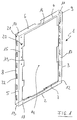
- the profile frame 1 shown in FIG. 1 first of all has a front profile frame level or front wall panel level, which is defined by the four edges 2, 3, 4 and 5.
- the horizontal edge areas 6 and 7 as well as the vertical edge areas 8 and 9 are folded or angled backwards from this front wall sheet plane.
- the edge areas 6, 7, 8, 9 are bent or angled so that they are at right angles to the front wall sheet plane .
- the upper edge area 6 and the lateral edge area 8 are connected to one another, for example by spot welding. This applies in the same way to the edges 11, 12 and 13 or the edge regions 7, 8 and 9.
- the front wall panel has a central recess 14, which is cut out or punched out of the front wall panel, only peripheral regions 15, 16, 17 and 18 remaining closed in the front wall panel 1.
- These edge regions 15, 16, 17 and 18 and the angled edges 6, 7, 8, 9 integrally formed thereon form an L-shaped frame or edge profile at each point of the profile frame.
- In the edge regions 15 and 17 there are further fastening openings 19 in the form of through bores for fastening installation parts, not shown in FIG. 1 , for example a cistern.
- a mark 20 is stamped, which serves for the exact positioning of the profile frame or the mounting device at a precisely defined height.
- a square recess 21 is arranged, which serves for the passage of a lock screw, not shown, in this area to fasten a mounting bracket, also not shown, with which the profile frame 1 can be fastened to a wall, not shown.
- the angled edges 8, 9 are provided over their entire length with regularly spaced slot-like recesses 22, which either on the one hand also for fastening a mounting bracket or on the other hand for fastening the profile frame to the vertically extending upright of a stud wall on which the profile frame 1 is in contact is bring serve.
- the profile frame or the mounting device as a whole is suitable both for use in front-wall mounting and in a stud wall.
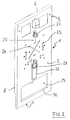
- the profile frame 1 has a front wall panel 2, the edge regions 6, 7, 8, 9 of which are bent at right angles from the front wall panel plane to the rear and are joined to one another in the region of the corners.
- no central recess is provided in the front wall panel 2; rather, the front wall panel 2 has a multiplicity of smaller recesses, openings, fastening openings and the like.
- the square recesses 23 are used for reaching through fastening screws for a urinal, not shown, it depending on the type of urinal used, which of the recesses 23 are then actually used.
- a cross-shaped groove-like bead 24 is provided, which serves for the local stiffening of the front wall panel 2 in this area.
- the recesses 25 and 26 are used to carry out the rinse water inlet 27 and the outlet pipe 28. These recesses are designed in the manner of a slot, in a manner known per se, in order to ensure good adaptability to various structural conditions.
- a recess 29 which, after the assembly device has been installed, for example in a bathroom, enables the sewage line to be connected to the drain pipe 28.
- the edge regions 30 of the recess 29 are likewise folded or angled backwards and thus contribute to the stiffening of the front wall panel 2 and thus of the profile frame 1 as a whole.
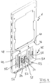
- FIG. 3 shows a further exemplary embodiment of a mounting device according to the invention using a one-piece profile frame 1.
- the mounting device shown here is used to attach and connect a washbasin.
- the basic structure of the mounting device or the profile frame 1 corresponds to the profile frame of the illustration according to FIG. 2 .
- three substantially vertical bead-like depressions for stiffening the front wall plate 2 are arranged in the exemplary embodiment according to FIG. 3 .
- the slot-like recesses 34, 35 are used to carry out the hot and cold water supply lines 36, 37, while the recess 38 is used to carry out the drain pipe 39.
- edge regions 40 of the recesses 34, 35 are recessed in the front wall panel 2 in such a way that the fastening elements 41 in the form of hexagon flange nuts do not protrude beyond the front wall panel plane. This design ensures that a covering or a plasterboard panel applied to the mounting device after the final assembly in any case rests fully on the front wall panel 2.
- slot-like recesses 42 which serve to receive the fastening screws, not shown, of a washstand, also not shown.
- the slot-like design allows adaptation to a wide variety of washbasin types.
- FIGS. 2 and 3 For the sake of clarity, the recesses for fastening the profile frame to a wall or to the uprights of a upright wall are not shown in FIGS. 2 and 3 .
- This mounting device which is used for the fastening connection of a bidet, has an upper first profile frame 1 and a lower profile frame 45.
- the upper profile frame 1 corresponds essentially to the profile frame shown in Fig. 1 .
- the second lower profile frame 45 is fastened with its upper profile edge or its upper profile edge 46 to the lower profile edge or the lower profile edge 47 of the upper frame 1.
- the attachment takes place via a number of welding points, which are attached in particular along the seam in the rear area of the angled edges. This design results in the area of the seam 46, 47, a highly stiffened cross member, consisting essentially of the two welded L-shaped profile areas of the profile frames 1 and 45.
- This stiffened cross member is approximately in the area in which no Shown screws or threaded rods that are screwed into the threaded holes 48, the bidet basin is attached.
- the tensile force exerted on the mounting device by the weight of the user and the pelvis in this area during the intended use of the bidet can be absorbed in an almost ideal manner by the stiffened cross member 46, 47.
- the second profile frame 45 has three recesses 49, 50 and 51 lying next to one another.
- the recess 50 is used in particular for Implementation of the hot and cold water connections 52, 53 and the water drain pipe 54.
- a web-like guide rail 55, 56 is arranged in the region of the profile frame 45.
- the two guide rails 55, 56 run parallel to one another and to the longitudinal side edges of both the profile frame 1 and the profile frame 45 and are thus aligned essentially vertically.
- the guide rails 55, 56 essentially have a U-shaped profile which is open to the rear.
- the lower edge region of the profile frame 45 facing the floor has recesses, not shown, directly below the guide rails 55, 56, through which appropriately designed foot parts 57, 58 can engage with the guide rails 55, 56.
- the foot parts 57, 58 are slidably guided in the guide rails 55, 56.
- the embodiment of an assembly device according to the invention shown in FIG. 5 is also designed as a two-part profile frame and is used for the load-bearing attachment of a toilet bowl.
- this exemplary embodiment essentially corresponds to the exemplary embodiment according to FIG. 4 .
- the upper profile frame 1 corresponds to the profile frame of FIG. 1 ; the lower profile frame 45 the profile frame 45 according to FIG. 4 .
- a cistern 60 is fastened in the upper profile frame 1, only indicated schematically.
- a rinsing water inflow to a toilet bowl, not shown, is made available via a connecting bend 61.
- the central recess 14 in the front panel of the upper profile frame 1 is designed so that the sheet metal section obtained by punching during the production of this recess 14 serves directly as a flat sheet metal blank for the production of the second profile frame 45.
- the recesses 49, 50 and 51 have edges 62 bent or angled backwards, which reinforce and stiffen the lower profile frame 45 as a whole and the guide rails 55, 56 in particular.
- This is particularly the case with a mounting device For use with a bidet or toilet bowl, this is advantageous, since when a toilet bowl is attached, for example, the entire load acting through the weight of a person using the toilet bowl is absorbed by the profiled guide rails 55, 56 as a pressure load.
- Fig. 6 the lower profile frame 45 and its connection to the upper profile frame 1 is shown again schematically.
- L-shaped reinforcement angles 63, 64 are arranged in the upper region of the guide rails 55, 56 or in the upper region of the extension of the web-like guide rails 55, 56.
- These reinforcement angles 63, 64 are fastened, for example welded, with their first leg pointing upwards in the illustration according to FIG. 6 on the upper profile edge of the lower profile frame 45. 6
- the reinforcement angles 63, 64 are welded to the region of the upper edge of the lower profile frame 45, which is part of the front wall panel plane.
- the reinforcement brackets 63, 64 cover with their second leg the fastening openings 65 for fastening the toilet bowl or bidet (not shown) and have threaded bores in this area for screwing in corresponding fastening screws.
- These reinforcement angles 63, 64 cause a partial transmission of the tensile load acting through the toilet bowl to the cross member formed by the interface of the two profile frames 1 and 45.
- a square recess 66 is arranged in the area of the reinforcement angles 63, 64 in this seam region and in the reinforcement angles themselves, which serves to engage a lock screw for fastening rearward-pointing support angles, not shown, for supporting the entire mounting device on a wall, also not shown .
- the lower area of the lower profile frame 45 pointing towards the floor is provided with a reinforcement profile inserted into the profile frame 45 from behind and fastened there by welding 67 provided.
- This reinforcement profile has essentially the shape of a U-profile.
- FIG. 6 shows the recesses 68 in the bottom region of the lower edge of the lower profile frame 45, through which the foot parts can be introduced into the web-like guide rails 55, 56.
- FIG. 7 shows an exemplary embodiment of a foot of a mounting device according to the invention, as shown in FIGS. 4 to 6, shown in an enlarged view.
- the foot 70 has two foot parts 57, 58, each of which is welded to a foot plate 71 with its first end.
- the footplate 71 has recesses 72 for the passage of fastening elements for fastening the footplate to the floor or a mounting rail.
- the footplate is provided in the area of its two axial ends with a nose-like notch 73, which serves to guide the foot 70 and thus the entire mounting device when moving the mounting device according to the invention on a C-shaped mounting rail when moving on the rail, not shown .
- the foot parts 57, 58 have an essentially U-shaped profile with a base surface 74 and two legs 75, 76. Both foot parts 57, 58 are of the same design.
- the base surface 74 has spaced-apart recesses 77, which serve on the one hand for the passage of fastening screws, not shown, and on the other hand for the rotationally fixed fastening of, for example, hook nuts.
- the foot or the foot parts 57, 58 are inserted from below through the recesses 68 into the web-like guide rails 55, 56 of the lower profile frame 45 until the desired height is reached. Then the foot parts 57 and 58 are fixed relative to the guide rails 55, 56 by means of fastening screws, not shown.
- the combination of the guide rails 55, 56 and the foot parts 57, 58 results in a box-like closed, highly rigid profile structure, as can be seen in particular from the schematic illustration according to FIG. 8 , which only schematically shows a section through the guide rail 55 with the foot part 57 inserted.
- the outer cross-sectional width of the foot part 57 is smaller than the inner cross-sectional width of the guide rail 55, so that the foot part 57 can be inserted into the guide rail 55 from below and can be guided linearly there.
- Both the base surface 74 of the U-shaped profile of the foot part 57 and the base surface 78 of the likewise U-shaped profile of the guide rail are each offset inwards in relation to one another in such a way that the two base surfaces 74 and 78 come to bear flat against one another. Due to this design can be achieved by means of a fastening screw, not shown, which extends through the recess 77 of the foot part 57 and the slot-like recess 79 of the guide rail, a reliable clamping effect fixing the two parts 57 and 55 in their relative position, in each case a total box-shaped rigid profile is formed by the two parts 55, 57.
Landscapes
- Health & Medical Sciences (AREA)
- Life Sciences & Earth Sciences (AREA)
- Engineering & Computer Science (AREA)
- Hydrology & Water Resources (AREA)
- Public Health (AREA)
- Water Supply & Treatment (AREA)
- Residential Or Office Buildings (AREA)
- Sanitary Device For Flush Toilet (AREA)
- Rolling Contact Bearings (AREA)
Applications Claiming Priority (2)
| Application Number | Priority Date | Filing Date | Title |
|---|---|---|---|
| DE19507843 | 1995-03-07 | ||
| DE19507843A DE19507843A1 (de) | 1995-03-07 | 1995-03-07 | Montagevorrichtung zur tragenden Befestigung einer Sanitäreinrichtung |
Publications (2)
| Publication Number | Publication Date |
|---|---|
| EP0731223A1 true EP0731223A1 (fr) | 1996-09-11 |
| EP0731223B1 EP0731223B1 (fr) | 2001-08-08 |
Family
ID=7755797
Family Applications (1)
| Application Number | Title | Priority Date | Filing Date |
|---|---|---|---|
| EP96101157A Expired - Lifetime EP0731223B1 (fr) | 1995-03-07 | 1996-01-27 | Dispositif de montage pour le support d'un aménagement sanitaire |
Country Status (3)
| Country | Link |
|---|---|
| EP (1) | EP0731223B1 (fr) |
| AT (1) | ATE204044T1 (fr) |
| DE (2) | DE19507843A1 (fr) |
Cited By (6)
| Publication number | Priority date | Publication date | Assignee | Title |
|---|---|---|---|---|
| EP0939170A1 (fr) * | 1998-02-26 | 1999-09-01 | E. Missel GmbH & Co. | Système de chasse d'eau |
| EP0959185A1 (fr) * | 1998-05-20 | 1999-11-24 | Friatec Aktiengesellschaft | Dispositif de fixation |
| EP0933480A3 (fr) * | 1998-01-28 | 2000-01-26 | Prosan, d.o.o. | Réservoir de chasse d'eau |
| FR2793823A1 (fr) * | 1999-05-18 | 2000-11-24 | Allia | Bati support d'appareil sanitaire suspendu |
| EP0985772A3 (fr) * | 1998-09-08 | 2001-02-28 | E. Missel GmbH & Co. | Dispositif d'assemblage pour appareils sanitaires |
| US20230138187A1 (en) * | 2021-10-29 | 2023-05-04 | Zhongshan Meitu Plastic Ind. Co., Ltd. | Mounting bracket |
Families Citing this family (3)
| Publication number | Priority date | Publication date | Assignee | Title |
|---|---|---|---|---|
| DE19736341C2 (de) * | 1997-08-21 | 2002-09-19 | Friatec Ag | Befestigungsvorrichtung |
| DE29805738U1 (de) | 1998-03-28 | 1998-07-23 | Stanulla, Michael, 88273 Fronreute | Montagevorrichtung für eine Toilettenschüssel o.dgl. |
| GB2637748A (en) * | 2024-02-02 | 2025-08-06 | Phoenix Product Development Ltd | Water closet |
Citations (3)
| Publication number | Priority date | Publication date | Assignee | Title |
|---|---|---|---|---|
| DE9305511U1 (de) * | 1993-04-13 | 1993-06-09 | Hager, Rupert, 8967 Oy-Mittelberg | Installationsrahmen für Sanitärgeräte |
| DE9407527U1 (de) * | 1994-05-06 | 1994-07-07 | Fa. Franz Viegener Ii, 57439 Attendorn | Modulelement für Möbeleinbauten bei Vorwandsystemen für sanitäre Anlagen |
| DE9414960U1 (de) * | 1994-09-15 | 1994-11-17 | Zako Installationsfertigelemente Gmbh, 32758 Detmold | Installationsblock |
Family Cites Families (3)
| Publication number | Priority date | Publication date | Assignee | Title |
|---|---|---|---|---|
| ATE90129T1 (de) * | 1989-10-24 | 1993-06-15 | Geberit Ag | Montageraumabdeckung fuer insbesondere geschaeumte installationsbausteine. |
| DE9014603U1 (de) * | 1989-11-10 | 1991-01-03 | Geberit Ag, Jona, St.Gallen | Fußstütze an einem Installationsblock |
| DE4106144C1 (fr) * | 1991-02-27 | 1992-07-16 | Mero-Werke Dr.-Ing. Max Mengeringhausen Gmbh & Co, 8700 Wuerzburg, De |
-
1995
- 1995-03-07 DE DE19507843A patent/DE19507843A1/de not_active Withdrawn
-
1996
- 1996-01-27 DE DE59607434T patent/DE59607434D1/de not_active Expired - Fee Related
- 1996-01-27 AT AT96101157T patent/ATE204044T1/de not_active IP Right Cessation
- 1996-01-27 EP EP96101157A patent/EP0731223B1/fr not_active Expired - Lifetime
Patent Citations (3)
| Publication number | Priority date | Publication date | Assignee | Title |
|---|---|---|---|---|
| DE9305511U1 (de) * | 1993-04-13 | 1993-06-09 | Hager, Rupert, 8967 Oy-Mittelberg | Installationsrahmen für Sanitärgeräte |
| DE9407527U1 (de) * | 1994-05-06 | 1994-07-07 | Fa. Franz Viegener Ii, 57439 Attendorn | Modulelement für Möbeleinbauten bei Vorwandsystemen für sanitäre Anlagen |
| DE9414960U1 (de) * | 1994-09-15 | 1994-11-17 | Zako Installationsfertigelemente Gmbh, 32758 Detmold | Installationsblock |
Cited By (9)
| Publication number | Priority date | Publication date | Assignee | Title |
|---|---|---|---|---|
| EP0933480A3 (fr) * | 1998-01-28 | 2000-01-26 | Prosan, d.o.o. | Réservoir de chasse d'eau |
| EP0939170A1 (fr) * | 1998-02-26 | 1999-09-01 | E. Missel GmbH & Co. | Système de chasse d'eau |
| US6128787A (en) * | 1998-02-26 | 2000-10-10 | E. Missel Gmbh & Co. | Flush system |
| EP1347105A1 (fr) * | 1998-02-26 | 2003-09-24 | E. Missel GmbH & Co. | Système de chasse d'eau |
| EP0959185A1 (fr) * | 1998-05-20 | 1999-11-24 | Friatec Aktiengesellschaft | Dispositif de fixation |
| EP0985772A3 (fr) * | 1998-09-08 | 2001-02-28 | E. Missel GmbH & Co. | Dispositif d'assemblage pour appareils sanitaires |
| FR2793823A1 (fr) * | 1999-05-18 | 2000-11-24 | Allia | Bati support d'appareil sanitaire suspendu |
| US20230138187A1 (en) * | 2021-10-29 | 2023-05-04 | Zhongshan Meitu Plastic Ind. Co., Ltd. | Mounting bracket |
| US11965621B2 (en) * | 2021-10-29 | 2024-04-23 | Zhongshan Meitu Plastic Ind. Co., Ltd. | Mounting bracket |
Also Published As
| Publication number | Publication date |
|---|---|
| ATE204044T1 (de) | 2001-08-15 |
| DE59607434D1 (de) | 2001-09-13 |
| DE19507843A1 (de) | 1996-09-12 |
| EP0731223B1 (fr) | 2001-08-08 |
Similar Documents
| Publication | Publication Date | Title |
|---|---|---|
| DE9412649U1 (de) | Rahmen für die Vorwandmontage von sanitären Einrichtungen | |
| EP0939170B1 (fr) | Système de chasse d'eau | |
| EP0731223B1 (fr) | Dispositif de montage pour le support d'un aménagement sanitaire | |
| EP0731231A1 (fr) | Elément d'assemblage | |
| EP3071757B1 (fr) | Arrangement avec un cadre de montage et un apprail sanitaire monté sur le cadre de montage | |
| DE19507765A1 (de) | Vorwandelement | |
| EP0860559A1 (fr) | Agencement avec une paroi support à barres profilées, en particulier paroi support pour appareils sanitaires | |
| EP0731228B1 (fr) | Equerre d'appui | |
| EP0324169B1 (fr) | Bloc d'installation | |
| EP1116830B1 (fr) | Elément de fixation pour le montage d'un appareil sanitaire dans une structure de support | |
| EP0731226B1 (fr) | Elément pour l'assemblage d'une installation sanitaire devant une paroi | |
| EP1990474B1 (fr) | Pied de support pour un cadre d'installation sanitaire | |
| EP0731224B1 (fr) | Elément de construction mural | |
| AT500901B1 (de) | Installationseinheit | |
| EP0877125B1 (fr) | Armature de montage d'articles sanitaires | |
| EP1803859A2 (fr) | Composant de paroi destiné à la fixation porteuse d'au moins un objet sanitaire et son procédé de fabrication | |
| EP1798354B1 (fr) | Dispositif de montage pour un appareil sanitaire | |
| DE19736341C2 (de) | Befestigungsvorrichtung | |
| EP1001099B1 (fr) | Elément d'installation | |
| DE19507743A1 (de) | Traverse für ein Vorwandelement | |
| DE202010000963U1 (de) | Duschablaufanordnung | |
| EP0733750A1 (fr) | Moyens de raccordement pour un réservoir de chasse d'eau | |
| DE202024100539U1 (de) | Stanz- und/oder Biegeteil und Vorwand-Montagerahmen für eine Sanitärinstallation | |
| DE29707090U1 (de) | Vorrichtung zur Wandmontage mindestens eines sanitären Gegenstandes | |
| EP4592464A2 (fr) | Dispositif de montage |
Legal Events
| Date | Code | Title | Description |
|---|---|---|---|
| PUAI | Public reference made under article 153(3) epc to a published international application that has entered the european phase |
Free format text: ORIGINAL CODE: 0009012 |
|
| AK | Designated contracting states |
Kind code of ref document: A1 Designated state(s): AT CH DE ES FR LI LU NL |
|
| 17P | Request for examination filed |
Effective date: 19970311 |
|
| 17Q | First examination report despatched |
Effective date: 19970429 |
|
| GRAG | Despatch of communication of intention to grant |
Free format text: ORIGINAL CODE: EPIDOS AGRA |
|
| GRAG | Despatch of communication of intention to grant |
Free format text: ORIGINAL CODE: EPIDOS AGRA |
|
| GRAH | Despatch of communication of intention to grant a patent |
Free format text: ORIGINAL CODE: EPIDOS IGRA |
|
| GRAH | Despatch of communication of intention to grant a patent |
Free format text: ORIGINAL CODE: EPIDOS IGRA |
|
| GRAA | (expected) grant |
Free format text: ORIGINAL CODE: 0009210 |
|
| AK | Designated contracting states |
Kind code of ref document: B1 Designated state(s): AT CH DE ES FR LI LU NL |
|
| PG25 | Lapsed in a contracting state [announced via postgrant information from national office to epo] |
Ref country code: FR Free format text: LAPSE BECAUSE OF FAILURE TO SUBMIT A TRANSLATION OF THE DESCRIPTION OR TO PAY THE FEE WITHIN THE PRESCRIBED TIME-LIMIT Effective date: 20010808 |
|
| REF | Corresponds to: |
Ref document number: 204044 Country of ref document: AT Date of ref document: 20010815 Kind code of ref document: T |
|
| REG | Reference to a national code |
Ref country code: CH Ref legal event code: EP |
|
| REF | Corresponds to: |
Ref document number: 59607434 Country of ref document: DE Date of ref document: 20010913 |
|
| RAP2 | Party data changed (patent owner data changed or rights of a patent transferred) |
Owner name: M. BLOCK GMBH |
|
| NLT2 | Nl: modifications (of names), taken from the european patent patent bulletin |
Owner name: M. BLOCK GMBH |
|
| PGFP | Annual fee paid to national office [announced via postgrant information from national office to epo] |
Ref country code: NL Payment date: 20011220 Year of fee payment: 7 |
|
| EN | Fr: translation not filed | ||
| PG25 | Lapsed in a contracting state [announced via postgrant information from national office to epo] |
Ref country code: LU Free format text: LAPSE BECAUSE OF NON-PAYMENT OF DUE FEES Effective date: 20020127 Ref country code: AT Free format text: LAPSE BECAUSE OF NON-PAYMENT OF DUE FEES Effective date: 20020127 |
|
| PG25 | Lapsed in a contracting state [announced via postgrant information from national office to epo] |
Ref country code: LI Free format text: LAPSE BECAUSE OF NON-PAYMENT OF DUE FEES Effective date: 20020131 Ref country code: CH Free format text: LAPSE BECAUSE OF NON-PAYMENT OF DUE FEES Effective date: 20020131 |
|
| PG25 | Lapsed in a contracting state [announced via postgrant information from national office to epo] |
Ref country code: ES Free format text: LAPSE BECAUSE OF FAILURE TO SUBMIT A TRANSLATION OF THE DESCRIPTION OR TO PAY THE FEE WITHIN THE PRESCRIBED TIME-LIMIT Effective date: 20020228 |
|
| PLBE | No opposition filed within time limit |
Free format text: ORIGINAL CODE: 0009261 |
|
| STAA | Information on the status of an ep patent application or granted ep patent |
Free format text: STATUS: NO OPPOSITION FILED WITHIN TIME LIMIT |
|
| 26N | No opposition filed | ||
| REG | Reference to a national code |
Ref country code: CH Ref legal event code: PL |
|
| PGFP | Annual fee paid to national office [announced via postgrant information from national office to epo] |
Ref country code: DE Payment date: 20030121 Year of fee payment: 8 |
|
| PG25 | Lapsed in a contracting state [announced via postgrant information from national office to epo] |
Ref country code: NL Free format text: LAPSE BECAUSE OF NON-PAYMENT OF DUE FEES Effective date: 20030801 |
|
| NLV4 | Nl: lapsed or anulled due to non-payment of the annual fee |
Effective date: 20030801 |