EP0731248A1 - Instrument de percussion - Google Patents
Instrument de percussion Download PDFInfo
- Publication number
- EP0731248A1 EP0731248A1 EP96103245A EP96103245A EP0731248A1 EP 0731248 A1 EP0731248 A1 EP 0731248A1 EP 96103245 A EP96103245 A EP 96103245A EP 96103245 A EP96103245 A EP 96103245A EP 0731248 A1 EP0731248 A1 EP 0731248A1
- Authority
- EP
- European Patent Office
- Prior art keywords
- piston
- steel
- percussion piston
- partially
- consist
- Prior art date
- Legal status (The legal status is an assumption and is not a legal conclusion. Google has not performed a legal analysis and makes no representation as to the accuracy of the status listed.)
- Withdrawn
Links
- 238000009527 percussion Methods 0.000 title claims description 45
- 239000000463 material Substances 0.000 claims abstract description 25
- 229910000831 Steel Inorganic materials 0.000 claims abstract description 20
- 239000010959 steel Substances 0.000 claims abstract description 20
- 229910052751 metal Inorganic materials 0.000 claims description 8
- 239000002184 metal Substances 0.000 claims description 8
- RTAQQCXQSZGOHL-UHFFFAOYSA-N Titanium Chemical compound [Ti] RTAQQCXQSZGOHL-UHFFFAOYSA-N 0.000 claims description 4
- 239000010936 titanium Substances 0.000 claims description 4
- 229910052719 titanium Inorganic materials 0.000 claims description 4
- 239000007787 solid Substances 0.000 claims 2
- 238000010276 construction Methods 0.000 description 4
- 229910000838 Al alloy Inorganic materials 0.000 description 3
- 239000011162 core material Substances 0.000 description 3
- 238000005553 drilling Methods 0.000 description 3
- 229910003439 heavy metal oxide Inorganic materials 0.000 description 2
- 239000002689 soil Substances 0.000 description 2
- 230000001133 acceleration Effects 0.000 description 1
- 238000009412 basement excavation Methods 0.000 description 1
- 238000010009 beating Methods 0.000 description 1
- 239000011248 coating agent Substances 0.000 description 1
- 238000000576 coating method Methods 0.000 description 1
- 238000011161 development Methods 0.000 description 1
- 230000018109 developmental process Effects 0.000 description 1
- 239000000843 powder Substances 0.000 description 1
- 238000009423 ventilation Methods 0.000 description 1
- XLYOFNOQVPJJNP-UHFFFAOYSA-N water Substances O XLYOFNOQVPJJNP-UHFFFAOYSA-N 0.000 description 1
Images


Classifications
-
- E—FIXED CONSTRUCTIONS
- E21—EARTH OR ROCK DRILLING; MINING
- E21B—EARTH OR ROCK DRILLING; OBTAINING OIL, GAS, WATER, SOLUBLE OR MELTABLE MATERIALS OR A SLURRY OF MINERALS FROM WELLS
- E21B4/00—Drives for drilling, used in the borehole
- E21B4/06—Down-hole impacting means, e.g. hammers
- E21B4/14—Fluid operated hammers
- E21B4/145—Fluid operated hammers of the self propelled-type, e.g. with a reverse mode to retract the device from the hole
-
- B—PERFORMING OPERATIONS; TRANSPORTING
- B25—HAND TOOLS; PORTABLE POWER-DRIVEN TOOLS; MANIPULATORS
- B25D—PERCUSSIVE TOOLS
- B25D17/00—Details of, or accessories for, portable power-driven percussive tools
- B25D17/06—Hammer pistons; Anvils ; Guide-sleeves for pistons
Definitions
- the invention relates to an impact device, in particular a pressure-driven ram boring device for earth bores, with a percussion piston which is moved back and forth in a housing.
- Such a ram boring machine primarily serves to lay or renew supply lines, such as water pipes or cables under roads or dams or other buildings and obstacles, without having to rip open the road surface or the earth's surface at the same time. This is done in such a way that the ram boring machine which moves forward in the ground due to the blows struck by the reciprocating percussion piston on the striking tip displaces the ground to the side and leaves a channel into which a supply line is drawn at the same time or later.
- the percussion tip is used to smash stones, old pipes or other obstacles and push them aside during the forward movement of the ram boring machine. H. to clear the way for the moving housing.
- the percussion tip When the percussion piston strikes the percussion tip, the percussion tip is accelerated and driven forward with the housing, but the housing must return when the percussion piston is retracted due to the friction of the soil remain at rest on the outer surface of the housing.
- the impact energy of the percussion piston and the mass of the ram boring machine in conjunction with the housing friction determine the speed at which the ram boring machine moves forward in the ground. While the force accelerating the percussion piston depends on the piston diameter and the pressure of the pressure medium and can therefore be influenced by this pressure, the mass of the percussion piston is material and construction-related and, if the ram boring machine is usually made of steel, cannot be influenced.
- the invention is based on the problem of creating an impact device, in particular a pressure-driven compact ram drilling device, which can be operated with comparatively higher impact energy.
- an impact device in particular a pressure-driven ram boring machine, with a housing, a percussion piston driven to and fro in the housing under pressure medium control, is proposed, in which, according to the invention, the percussion piston is at least partially made of a higher density material than at least some of the other components of the impact device consists.
- a percussion piston which at least partially consists of a higher density material than the other components of the impact device, very short impact devices, in particular pressure-driven ram boring devices, can be built, which nevertheless are powerful because the impact energy is high depending on the density, although the path available to accelerate the percussion piston is shorter than with conventional ram boring machines and the volume of the piston may be less than with a conventional ram boring machine.
- Such short ram boring machines can be used in cramped construction site conditions, since only short construction pits are required for such devices and these are suitable for starting from a revision shaft to smash existing old pipelines.
- the percussion piston in a percussion device is a highly stressed component, the striking surface of which, for example, a percussion tool, in particular a percussion tip, must consist of a hard and tough material
- the percussion piston can advantageously at least partially from a high-strength and tough steel and the rest Components of the impact device consist at least partially of a material of lower density than steel.
- the ram boring machine with the exception of the percussion piston, has a reduced mass compared to conventional devices, which therefore also requires less energy for acceleration.
- the percussion piston can at least partially consist of a material with a higher density than steel and the other components at least partially consist of steel.
- the ratio between the mass of the impact piston and the mass of the other components of the impact device is advantageously improved and the energy available for propulsion is increased.
- Constructive developments of the invention can consist in that the front part of the percussion piston with a striking surface acting on the striking tip consists of a high-strength and tough material such as steel or hard metal and a tubular end part with a lower density than steel or hard metal is connected to the front part.
- a tubular percussion piston with a striking surface acting on the striking tip can consist of a high-strength and tough material and a cavity in the striking piston adjacent to the striking surface can be filled with a core made of a material of higher density than the rest of the material of the striking piston.
- This material can have a relatively low strength, since it is not mechanically stressed. It is conceivable to z. B. pour out with lead or fill with a high density powder, such as a heavy metal oxide.
- the components of the impact device can advantageously consist of a light metal, for example titanium and / or an aluminum alloy. In this case it is advisable to provide it with a wear-resistant surface. This can be done by hardening or hard coating.
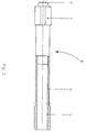
- the ram boring machine shown schematically in FIG. 1 consists of a tubular housing 1, at the front end of which a striking tip 2 is arranged.
- a percussion piston 3 is pressurized with pressure medium and is arranged to be able to move back and forth in a controlled manner by means of a control tube 4.
- the housing is closed at the rear end by an end plate 5, which has axially parallel ventilation holes 6 for compressed air used during operation of the ram boring machine.
- the control tube 4 is fastened to the end plate 5 by means of a tubular extension 15 of smaller diameter and connected to a compressed air hose 7.
- the percussion piston 3 consists of a front part 9 which is guided in the housing bore 8. This front part 9 has at its front end a striking surface 10 which acts on a corresponding striking surface of the striking tip 2.
- the front part 9 of the percussion piston 3 is connected via an intermediate piece 11 of smaller diameter to a cylindrical end part 12 which is also guided in the housing bore 8 and in whose bore 14 the fixed control tube 4 engages.
- the front part 9 with the face 10 z. B. of hard metal with a density of 12 x 10 3 kg / m 3 , while the end part 12 consists of steel.
- the end part 12 On a pin of the front part 9, the end part 12 is shrunk or otherwise securely fastened.
- the massive front part 9 is impact-resistant and tough enough to sustain the blows on the striking tip 2, while the material for the end part 12 has no special requirements.
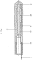
- the front part 9 is made of the same material as the end part 12, and a bore 13 extends in the front part into the area adjacent to the striking surface 10.
- the bore 13 a core 16 made of a material high density, such as lead or a heavy metal oxide. No high mechanical requirements are imposed on this core material, while the front part 9 and the end part 12 consist of a strong and tough steel.
- FIG. 4 shows a ram boring machine with external control consisting of a tubular housing 17, in the bore 18 of which the percussion piston moves from a front part 20 and an end part 21.
- the percussion piston 21 is controlled via a control tube 22, to which compressed air is supplied via a compressed air hose 7. It delivers its energy to the housing 17 via the striking surface 19.
- the other components of the ram drilling device can consist of light metal, in particular titanium and / or an aluminum alloy .
- the impact tip 2 can optionally consist of high-strength titanium, while the housing 1, the control tube 4, the extension 15 and the end plate 5 consist of an aluminum alloy.
- the overall machine becomes lighter since the percussion piston and possibly the piston stroke can be smaller with the same output, which reduces the mass of the entire machine housing surrounding the percussion piston. This means that the overall weight of the machine is reduced, despite the heavy piston. This makes it easier to handle respectively more user-friendly. With the compact machine, smaller construction pits and less soil excavation are required and the surface is less destroyed.
- the invention is not limited to a pressure-driven ram boring machine; rather, dynamic beating devices with a reciprocating percussion piston can be designed in the manner according to the invention in order to nevertheless generate a high impact energy with relatively small travel of the percussion piston even with a small-volume percussion piston.
Landscapes
- Engineering & Computer Science (AREA)
- Mechanical Engineering (AREA)
- Life Sciences & Earth Sciences (AREA)
- Geology (AREA)
- Mining & Mineral Resources (AREA)
- Physics & Mathematics (AREA)
- Environmental & Geological Engineering (AREA)
- Fluid Mechanics (AREA)
- General Life Sciences & Earth Sciences (AREA)
- Geochemistry & Mineralogy (AREA)
- Earth Drilling (AREA)
Applications Claiming Priority (2)
| Application Number | Priority Date | Filing Date | Title |
|---|---|---|---|
| DE1995108542 DE19508542A1 (de) | 1995-03-10 | 1995-03-10 | Schlaggerät |
| DE19508542 | 1995-03-10 |
Publications (1)
| Publication Number | Publication Date |
|---|---|
| EP0731248A1 true EP0731248A1 (fr) | 1996-09-11 |
Family
ID=7756238
Family Applications (1)
| Application Number | Title | Priority Date | Filing Date |
|---|---|---|---|
| EP96103245A Withdrawn EP0731248A1 (fr) | 1995-03-10 | 1996-03-02 | Instrument de percussion |
Country Status (2)
| Country | Link |
|---|---|
| EP (1) | EP0731248A1 (fr) |
| DE (1) | DE19508542A1 (fr) |
Cited By (5)
| Publication number | Priority date | Publication date | Assignee | Title |
|---|---|---|---|---|
| GB2334053A (en) * | 1998-02-07 | 1999-08-11 | Tracto Technik | Percussion boring machine with hard contacting surfaces |
| WO2004014616A1 (fr) * | 2002-07-04 | 2004-02-19 | Atlas Copco Electric Tools Gmbh | Outil portatif |
| EP1642685A1 (fr) * | 2004-09-30 | 2006-04-05 | HILTI Aktiengesellschaft | Marteau perforateur et/ou burineur |
| WO2012143176A1 (fr) * | 2011-04-19 | 2012-10-26 | Robert Bosch Gmbh | Percuteur |
| WO2015189754A1 (fr) * | 2014-06-09 | 2015-12-17 | O.M.Ler 2000 S.R.L. | Vibrateur d'extraction de noyau ou marteau pneumatique pour l'extraction de noyaux de pièces de fonderie dotées d'une chemise d'alliage d'aluminium |
Families Citing this family (2)
| Publication number | Priority date | Publication date | Assignee | Title |
|---|---|---|---|---|
| DE102010015465A1 (de) | 2010-04-16 | 2011-10-20 | Tracto-Technik Gmbh & Co. Kg | Erdbohrvorrichtung |
| DE102024110360A1 (de) | 2023-04-14 | 2024-10-17 | Milwaukee Electric Tool Corporation | Schlagwerkzeugamboss und Verfahren zum Herstellen |
Citations (3)
| Publication number | Priority date | Publication date | Assignee | Title |
|---|---|---|---|---|
| US3797586A (en) * | 1971-12-20 | 1974-03-19 | Bell Telephone Labor Inc | Mole with decoupled nose and body |
| GB2026572A (en) * | 1978-06-17 | 1980-02-06 | Inst Gornogo Dela Sibirskogo O | Pneumatic percussion tool |
| US4448339A (en) * | 1981-12-03 | 1984-05-15 | Ronald Pettigrew | Nail driving and recessing tool |
-
1995
- 1995-03-10 DE DE1995108542 patent/DE19508542A1/de not_active Withdrawn
-
1996
- 1996-03-02 EP EP96103245A patent/EP0731248A1/fr not_active Withdrawn
Patent Citations (3)
| Publication number | Priority date | Publication date | Assignee | Title |
|---|---|---|---|---|
| US3797586A (en) * | 1971-12-20 | 1974-03-19 | Bell Telephone Labor Inc | Mole with decoupled nose and body |
| GB2026572A (en) * | 1978-06-17 | 1980-02-06 | Inst Gornogo Dela Sibirskogo O | Pneumatic percussion tool |
| US4448339A (en) * | 1981-12-03 | 1984-05-15 | Ronald Pettigrew | Nail driving and recessing tool |
Cited By (6)
| Publication number | Priority date | Publication date | Assignee | Title |
|---|---|---|---|---|
| GB2334053A (en) * | 1998-02-07 | 1999-08-11 | Tracto Technik | Percussion boring machine with hard contacting surfaces |
| GB2334053B (en) * | 1998-02-07 | 2002-11-13 | Tracto Technik | Percussion boring machine |
| WO2004014616A1 (fr) * | 2002-07-04 | 2004-02-19 | Atlas Copco Electric Tools Gmbh | Outil portatif |
| EP1642685A1 (fr) * | 2004-09-30 | 2006-04-05 | HILTI Aktiengesellschaft | Marteau perforateur et/ou burineur |
| WO2012143176A1 (fr) * | 2011-04-19 | 2012-10-26 | Robert Bosch Gmbh | Percuteur |
| WO2015189754A1 (fr) * | 2014-06-09 | 2015-12-17 | O.M.Ler 2000 S.R.L. | Vibrateur d'extraction de noyau ou marteau pneumatique pour l'extraction de noyaux de pièces de fonderie dotées d'une chemise d'alliage d'aluminium |
Also Published As
| Publication number | Publication date |
|---|---|
| DE19508542A1 (de) | 1996-09-12 |
Similar Documents
| Publication | Publication Date | Title |
|---|---|---|
| DE2157259C3 (de) | Rammbohrgerät | |
| DE69635619T2 (de) | Stossdämpfermechanismus für eine hydraulische hämmervorrichtung | |
| DE3710162C1 (de) | Rammbohrgeraet mit beweglichem Meissel | |
| EP0354943A1 (fr) | Outil percutant pour instruments chirurgicaux. | |
| DE3439475A1 (de) | Winkelvorsatz zur uebertragung und umlenkung der antriebsenergie | |
| DE2924393A1 (de) | Bohrvorrichtung zum ueberlagerungsbohren | |
| DE2217507B1 (de) | Hydraulischer hammer und seine verwendung fuer bohrhaemmer | |
| DE2630091C3 (de) | Verfahren und Vorrichtung zum Brechen eines harten kompakten Materials, insbesondere eines Gesteins | |
| DE69636939T2 (de) | Methode zur regulierung von bohrmaschinen und gesteinsbohrer | |
| DE3124524C2 (de) | Rammvorrichtung für selbstgetriebene pneumatische Rammbohrgeräte | |
| EP0663270B1 (fr) | Marteau à percussion rotative et/ou rectiligne | |
| DE10112985A1 (de) | Schlagbohrkopf | |
| DE8000153U1 (de) | Hammer zum zerstoeren von festen abzutragenden materialien | |
| DE19508542A1 (de) | Schlaggerät | |
| DE10146024C2 (de) | Schlagvorrichtung, Erdbohrvorrichtung und Verfahren zum Vortrieb eines Bohrkopfes oder eines Aufweitkörpers | |
| EP0847836B1 (fr) | Appareil à percussion mû par un fluide sous pression | |
| DE4003189A1 (de) | Rammvorrichtung | |
| EP1157787B1 (fr) | Procédé pour travailler le sol et des pierres et outil de percussion hydraulique | |
| DE3926787C2 (de) | Verfahren und Vorrichtung zum Einbringen und Verankern eines Zugpfahls | |
| DE19534115A1 (de) | Vorrichtung zur Übertragung der Schlagenergie von einer Schlagmasse auf ein einzurammendes Element | |
| DE3590831C2 (de) | D{mpfungseinrichtung f}r Schlagh{mmer von Vorrichtungen zum Auffahren von Grubenbauen in hartem Gestein | |
| DE2053336A1 (de) | Mittels eines elastischen Druck mediums antreibbarer Motor | |
| EP0998376B1 (fr) | Dispositif de percussion pour la liberation par percussion d'objets bloques | |
| DE3027990A1 (de) | Selbstgetriebenes rammbohrgeraet | |
| DE102008036722B4 (de) | Verfahren, Vorrichtung und Bohrkopf zum Einbringen einer Bohrung in das Erdreich |
Legal Events
| Date | Code | Title | Description |
|---|---|---|---|
| PUAI | Public reference made under article 153(3) epc to a published international application that has entered the european phase |
Free format text: ORIGINAL CODE: 0009012 |
|
| AK | Designated contracting states |
Kind code of ref document: A1 Designated state(s): CH FR GB LI |
|
| STAA | Information on the status of an ep patent application or granted ep patent |
Free format text: STATUS: THE APPLICATION IS DEEMED TO BE WITHDRAWN |
|
| 18D | Application deemed to be withdrawn |
Effective date: 19970312 |