EP0731250A2 - Dispositif de coupe pour trépan de forage rotatif, son procédé de montage et son procédé de fabrication - Google Patents
Dispositif de coupe pour trépan de forage rotatif, son procédé de montage et son procédé de fabrication Download PDFInfo
- Publication number
- EP0731250A2 EP0731250A2 EP96301439A EP96301439A EP0731250A2 EP 0731250 A2 EP0731250 A2 EP 0731250A2 EP 96301439 A EP96301439 A EP 96301439A EP 96301439 A EP96301439 A EP 96301439A EP 0731250 A2 EP0731250 A2 EP 0731250A2
- Authority
- EP
- European Patent Office
- Prior art keywords
- carrier
- cutter assembly
- cutting element
- disc
- drill bit
- Prior art date
- Legal status (The legal status is an assumption and is not a legal conclusion. Google has not performed a legal analysis and makes no representation as to the accuracy of the status listed.)
- Withdrawn
Links
Images
Classifications
-
- E—FIXED CONSTRUCTIONS
- E21—EARTH OR ROCK DRILLING; MINING
- E21B—EARTH OR ROCK DRILLING; OBTAINING OIL, GAS, WATER, SOLUBLE OR MELTABLE MATERIALS OR A SLURRY OF MINERALS FROM WELLS
- E21B10/00—Drill bits
- E21B10/46—Drill bits characterised by wear resisting parts, e.g. diamond inserts
- E21B10/56—Button-type inserts
- E21B10/567—Button-type inserts with preformed cutting elements mounted on a distinct support, e.g. polycrystalline inserts
Definitions
- the invention relates to cutter assemblies for rotary drag-type drill bits, for use in drilling or coring holes in subsurface formations, and of the kind comprising a bit body having a shank for connection to a drill string, a plurality of cutter assemblies mounted at the surface of the bit body, and a passage in the bit body for supplying drilling fluid to the surface of the bit body for cooling and/or cleaning the cutter assemblies.
- bit body may be machined from metal, usually steel, sockets to receive the cutter assemblies being machined in the bit body.
- the bit body may be moulded from tungsten carbide matrix material using a powder metallurgy process.
- the present invention relates to the structure of cutter assemblies, for use in such a drill bit, and of the kind comprising a preform polycrystalline diamond cutting element mounted on a carrier of material which is less hard than the diamond, the carrier then in turn being secured within a socket in the bit body.
- a common form of cutting element comprises a flat tablet, usually circular, having a front cutting table of polycrystalline diamond bonded to a substrate of less hard material, such as cemented tungsten carbide.
- the layer of polycrystalline diamond is formed and bonded to the substrate in a high pressure, high temperature press, and one or more transition layers may sometimes be provided between the cutting table and substrate.
- the general details of manufacture of such cutting elements are well known and do not form a part of the present invention.
- the carrier has usually been in the form of a cylindrical post or stud and may, for example, also be formed from cemented tungsten carbide.
- Each cutting element is normally mounted on its carrier by brazing the rear surface of the substrate to a surface of the carrier.
- Such current forms of carrier have certain disadvantages.
- the cutting element is normally brazed to an inclined surface at one end of a cylindrical post, the opposite end of the post being received in a corresponding cylindrical blind socket in the bit body.
- the present invention sets out to provide improved forms of cutter assembly, and methods of mounting such assemblies on a drill bit.
- a cutter assembly for a rotary drag-type drill bit including a preform cutting element comprising a front facing table of polycrystalline diamond bonded to a substrate of a material which is less hard than the diamond, the cutting element being mounted on a carrier, also of a material which is less hard than the diamond, which carrier is, in use, received in a socket in the body ofthe drill bit, at least part ofthe carrier comprising a portion of a disc, and having opposite side faces defined by parts of opposite side surfaces of the disc, and a curved edge surface defined by part of the peripheral edge of the disc.
- the carrier comprises a portion of a disc, it may be generally sector-shaped, being of large extent in side view but narrow in cross-section.
- the shape therefore allows for strong cutter support, permitting high exposure of the cutting element on the carrier, while at the same time allowing close packing of adjacent cutter assemblies.
- the large side area provided by the cutter provides a large area for brazing so that the cutter may be firmly secured within its socket.
- the carrier may further include front and rear surfaces extending transversely of the side surfaces and curved edge surface.
- the cutting element may be bonded to the front surface of the carrier.
- Said front and rear surfaces may meet at a location remote from the curved edge ofthe carrier, so that, as mentioned above, the carrier is substantially sector-shaped. At least one of said surfaces may extend substantially normally to the curved edge of the carrier.
- Said opposite side surfaces of the carrier preferably taper inwardly, as viewed in cross-section, as they extend towards the curved edge surface of the carrier. Such tapered arrangement further improves the packing density of adjacent cutter assemblies.
- the invention also provides other forms of cutter assembly which achieve similar advantages but where the carrier is not in the form of part of a disc.
- a cutter assembly for a rotary drag-type drill bit of the kind previously referred to wherein at least part of the carrier is in the form of a block having a front surface, a rear surface, opposite side surfaces and a bottom edge surface, at least one of said front and rear surfaces being substantially flat, and the opposite side surfaces tapering inwardly, as viewed in cross-section, as they extend towards the bottom edge surface of the carrier.
- said tapering opposite side surfaces of the carrier are also flat.
- the flat front or rear surface may extend substantially at right angles to said bottom edge surface, or may be inclined thereto at an angle which is greater or less than a right angle.
- the other of the front and rear surfaces may also be substantially flat, in which case the front and rear surfaces may be substantially parallel to one another.
- the invention also provides a method of mounting a cutter assembly of any of the above kinds in the body of a drill bit, the method comprising providing on the surface of the bit body an upstanding blade extending outwardly away from the longitudinal axis of rotation of the bit, the blade having a leading edge surface extending away from the surface ofthe bit body, forming a slot in the blade by passing a machine tool, in one or a succession of passes, through said leading edge surface and transversely through at least a part of the blade, the tool being of a cross-sectional shape corresponding to the cross-sectional shape of at least part of the carrier of the cutter assembly, and then brazing or otherwise securing said part of the carrier of the cutter assembly in said slot.
- the part of the carrier of the cutter assembly comprises a portion of a disc
- said tool is moved along a part-circular path of the same radius as the disc. In other cases the tool may be traversed along a linear path.
- the blade on the bit body may have a trailing edge surface, opposite said leading edge surface, and in this case the slot may also pass through said trailing edge surface.
- the invention also includes within its scope a method of forming a carrier for a cutter assembly according to the first aspect of the invention, the method comprising forming a circular disc from a material suitable for the carrier of a cutter assembly, cutting said disc into a plurality of sectors by spaced cuts extending inwardly from the periphery of the disc, and mounting a cutting element on a surface of each sector remote from the curved edge of the sector.
- Said cuts may extend radially of the disc, or at an angle to a radius.
- Each cut may be substantially straight or may comprise two or more stretches at an angle to one another.
- the method may also include further steps of shaping each sector subsequently to its being cut from the disc.
- back-up elements are located on the bit body rearwardly of some or all of the cutter assemblies.
- Such elements may comprise bearing elements, abrasion elements, or secondary cutters.
- the elements provide a back-up for the cutter assemblies, in case a cutter assembly becomes damaged or excessively worn, and may also absorb excessive loads which would otherwise be applied to the cutter assemblies, causing damage, such as impact loads.
- the back-up element is currently located in a separate socket spaced rearwardly of the cutter assembly.
- the back-up element may, for example, comprise a stud of tungsten carbide or infiltrated matrix material impregnated with elements of natural or synthetic diamond, or a secondary cutter similar to the primary cutter assembly.
- the back-up element Due to the necessity of providing a separate socket, the back-up element has to be spaced a significant distance rearwardly of its associated cutter assembly and where the cutter assemblies are mounted on blades on the bit body, this requires the blades to be wider than they would otherwise be if the back-up elements were not provided.
- the width of each blade has to be increased to accommodate back-up elements, the open area between adjacent blades must be correspondingly reduced.
- a cutter assembly for a rotary drag-type drill bit including a preform cutting element comprising a front facing table of polycrystalline diamond bonded to a substrate of a material which is less hard than the diamond, the cutting element being mounted on a carrier, also of a material which is less hard than the diamond, and which in use is received in a socket in the body ofthe drill bit, the cutter assembly including a back-up element mounted in a socket in the carrier rearwardly of the cutting element with respect to the normal direction of forward rotation of the cutting element during drilling.
- the back-up element may be an abrasion element comprising natural or synthetic diamond elements embedded in a carrier of material, such as tungsten carbide or infiltrated matrix material, which is less hard than the diamond.
- the back-up element may comprise a portion of the carrier of the cutter assembly which is located rearwardly of the cutting element with respect to the normal direction of forward rotation ofthe cutting element during drilling, which portion projects further away from the bit than the cutting element itself whereby, in use, the projecting portion engages the formation before the cutting element.
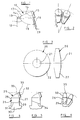
- Figure 1 shows diagrammatically a cutter assembly 10 mounted in a socket 11 in a blade 12 which extends outwardly away from the longitudinal axis of rotation of a drag-type drill bit.
- the construction of such drill bits generally is well known and will not therefore be described in further detail.
- the bit body may be machined from steel or moulded from solid infiltrated matrix material using well known powder metallurgy processes.
- the blade 12 may be formed with a hard facing layer 13.
- a plurality of cutter assemblies are normally mounted side-by-side along each blade.
- the cutter assembly 10 comprises a carrier 14 of tungsten carbide or other suitable material on which is mounted a cutting element 15.
- the cutting element 15 is in the form of a circular tablet and comprises a front facing table of polycrystalline diamond bonded to a substrate of tungsten carbide. The rear surface of the tungsten carbide substrate is brazed to a surface on the carrier 14.
- the carrier 14 is generally in the form of a sector of a disc and comprises a front surface 16, a rear surface 17, and a lower curved edge surface 18.
- the rear surface 17 comprises three portions each portion being inclined at an angle to the adjacent one.
- the opposite side surfaces 19 of the carrier 14 taper inwardly as they extend towards the curved edge surface 18 of the carrier. As may be seen from Figure 2, this permits close packing of adjacent cutter assemblies on a curved portion of the blade 12.
- the side surfaces 19 may be flat, or may be ridged or serrated.
- the sector shape of the carrier 14 provides large areas on each side of the carrier for brazing it into the socket 11 and thus provides secure mounting and strength for the carrier while, at the same time, the narrow tapering cross-sectional width of the carrier allows for close packing of adjacent assemblies.
- the strong support provided by the carrier also allows high exposure of the cutting element 15 above the surface of the blade 12, as may be seen from Figure 1.
- Figure 3 shows in plan view and section the shape of a disc 20 from which may be formed a number of the carriers 14.
- the disc comprises a central circular portion 21 the opposite faces of which are parallel, and an outer annular portion 22 where the opposite faces taper towards one another.
- Four carriers 14 can be cut from the disc 20, but it will be appreciated that a greater or lesser number of carriers of different shape may also be cut from a single disc if required.
- the disc 20 is first cut into the appropriate number of sectors and each sector is then further shaped to provide the required configuration of the carrier, particularly those parts thereof which project beyond the blade 12.
- the surface 16 to which the cutting element 15 is brazed may be ground.
- the socket 11 in the blade 12 is in the form of a slot extending from the front face 23 of the blade and the outer face 24. Since the carrier is formed from a disc, the slot 11 may be readily formed by passing through the blade 12, in one or more passes, a machining tool the cross-sectional shape of which corresponds to the cross-sectional shape ofthe disc 20. Thus, the tool may itselfcomprise a cutting disc of the same shape as the disc 20 which is rotated so as to cut the slot 11 in the blade 12.
- Figures 4-6 show alternative arrangements according to the invention where the carrier is not formed from part of a disc.
- the carrier 25 of the cutter assembly includes a lower part 26 in the form of a block having a front face 27, a rear face 28 and tapering side faces 29.
- the blade 30 on the drill bit is then formed with a straight taper-sided slot 31 cut through the whole width ofthe blade 30 and corresponding in cross-section to the shape of the block part 26 of the carrier 25.
- the cutting element 32 is brazed to an inclined surface on a portion 33 of the carrier which is integral with the block 26 but which projects beyond the surface of the blade 30 when the block 26 is received within the slot 31.
- Figure 5 shows an alternative arrangement where the lower surface 34 of the block part of the carrier is inclined, so as to provide greater resistance to rearward loads on the cutter assembly.
- FIG 6 is a front view of two adjacent cutter assemblies of the kind shown in Figures 4 and 5 and it will be seen that the tapering sides 29 of the block part 26 allow close packing of adjacent assemblies as in the previously described arrangement.
- each cutting element 32 is in the form of a tablet but in this case it is not of circular form.
- a number of the shaped cutting elements 32 may comprise sectors cut from a flat annular ring comprising an annular table of polycrystalline diamond bonded to a corresponding annular substrate of tungsten carbide.
- the cutting elements 32 are formed by making spaced radial cuts in the annulus and then rounding the part of each sector which formed the inner periphery so as to provide the cutting edge 35 of the cutting element.
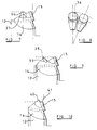
- Figures 7 and 8 show a modified version of the cutter assembly shown in Figures 1 and 2, and corresponding parts have corresponding reference numerals.
- a back-up bearing element 36 is located rearwardly of the cutting element 15 and is received in a socket 37 in the part of the carrier 14 which projects above the outer surface of the blade 12.
- the back-up element 36 may be of any suitable form.
- it may comprise a cylindrical domed stud of tungsten carbide or infiltrated matrix material impregnated with natural or synthetic diamond elements.
- it might be a simple tungsten carbide stud which acts solely as a bearing element without having any abrading action.
- the stud might have embedded in it one or more blocks of polycrystalline diamond material.
- the socket 37 for the back-up element requires to be cut in the carrier and the carrier is therefore preferably formed from a material which can be readily machined.
- the carrier may be of the kind where the tungsten carbide is combined with a proportion of tungsten metal, which has the effect of improving machinability.
- a secondary cutting element 38 bonded to an inclined surface 39 formed on the carrier 14.
- the secondary cutting element 38 may be of generally similar form to the primary cutting element 15 but may be mounted at a different back rake angle, as shown in Figure 9.
- a part of the carrier itself may be shaped so as to act as a bearing element, and such an arrangement is shown in Figure 10.
- the part of the carrier 14 rearwardly of the cutting element 15 is shaped to provide a projection 40 which projects outwardly beyond the cutting edge 41 of the cutting element 15.
- the projection 40 engages the formation before the cutting edge 41 does, and this may reduce the risk of impact damage to the cutting element 15 when the drill bit is first introduced downhole and may enhance dynamic stability of the drill bit when new. It will be appreciated that the projection 40 will only be effective when the bit is new, since it becomes worn away comparatively rapidly as drilling proceeds.
Landscapes
- Engineering & Computer Science (AREA)
- Life Sciences & Earth Sciences (AREA)
- Mining & Mineral Resources (AREA)
- Geology (AREA)
- Mechanical Engineering (AREA)
- Physics & Mathematics (AREA)
- Environmental & Geological Engineering (AREA)
- Fluid Mechanics (AREA)
- Chemical & Material Sciences (AREA)
- Crystallography & Structural Chemistry (AREA)
- General Life Sciences & Earth Sciences (AREA)
- Geochemistry & Mineralogy (AREA)
- Drilling Tools (AREA)
- Earth Drilling (AREA)
Applications Claiming Priority (2)
| Application Number | Priority Date | Filing Date | Title |
|---|---|---|---|
| GB9504634A GB2298665B (en) | 1995-03-08 | 1995-03-08 | Improvements in or relating to cutter assemblies for rotary drill bits |
| GB9504634 | 1995-03-08 |
Publications (2)
| Publication Number | Publication Date |
|---|---|
| EP0731250A2 true EP0731250A2 (fr) | 1996-09-11 |
| EP0731250A3 EP0731250A3 (fr) | 1997-11-26 |
Family
ID=10770841
Family Applications (1)
| Application Number | Title | Priority Date | Filing Date |
|---|---|---|---|
| EP96301439A Withdrawn EP0731250A3 (fr) | 1995-03-08 | 1996-03-04 | Dispositif de coupe pour trépan de forage rotatif, son procédé de montage et son procédé de fabrication |
Country Status (3)
| Country | Link |
|---|---|
| US (1) | US5720357A (fr) |
| EP (1) | EP0731250A3 (fr) |
| GB (1) | GB2298665B (fr) |
Cited By (1)
| Publication number | Priority date | Publication date | Assignee | Title |
|---|---|---|---|---|
| WO2021188267A1 (fr) * | 2020-03-18 | 2021-09-23 | Baker Hughes Oilfield Operations Llc | Outils de forage de terrain comprenant des éléments de coupe adjacents hydrauliques améliorés et procédés de formation |
Families Citing this family (35)
| Publication number | Priority date | Publication date | Assignee | Title |
|---|---|---|---|---|
| GB9621216D0 (en) * | 1996-10-11 | 1996-11-27 | Camco Drilling Group Ltd | Improvements in or relating to cutting structures for rotary drill bits |
| FR2756002B1 (fr) * | 1996-11-20 | 1999-04-02 | Total Sa | Outil de forage a lames avec taillants de reserve et canaux d'evacuation des deblais generes par les taillants |
| BE1010801A3 (fr) * | 1996-12-16 | 1999-02-02 | Dresser Ind | Outil de forage et/ou de carottage. |
| US6068072A (en) * | 1998-02-09 | 2000-05-30 | Diamond Products International, Inc. | Cutting element |
| US6792326B1 (en) * | 1999-05-24 | 2004-09-14 | Potomac Photonics, Inc. | Material delivery system for miniature structure fabrication |
| US6394202B2 (en) * | 1999-06-30 | 2002-05-28 | Smith International, Inc. | Drill bit having diamond impregnated inserts primary cutting structure |
| US6460631B2 (en) * | 1999-08-26 | 2002-10-08 | Baker Hughes Incorporated | Drill bits with reduced exposure of cutters |
| US6408958B1 (en) * | 2000-10-23 | 2002-06-25 | Baker Hughes Incorporated | Superabrasive cutting assemblies including cutters of varying orientations and drill bits so equipped |
| US7395882B2 (en) | 2004-02-19 | 2008-07-08 | Baker Hughes Incorporated | Casing and liner drilling bits |
| US7954570B2 (en) * | 2004-02-19 | 2011-06-07 | Baker Hughes Incorporated | Cutting elements configured for casing component drillout and earth boring drill bits including same |
| US8146683B2 (en) * | 2004-02-19 | 2012-04-03 | Baker Hughes Incorporated | Drilling out casing bits with other casing bits |
| US7624818B2 (en) * | 2004-02-19 | 2009-12-01 | Baker Hughes Incorporated | Earth boring drill bits with casing component drill out capability and methods of use |
| US7455125B2 (en) * | 2005-02-22 | 2008-11-25 | Baker Hughes Incorporated | Drilling tool equipped with improved cutting element layout to reduce cutter damage through formation changes, methods of design and operation thereof |
| US8141665B2 (en) * | 2005-12-14 | 2012-03-27 | Baker Hughes Incorporated | Drill bits with bearing elements for reducing exposure of cutters |
| US7621351B2 (en) * | 2006-05-15 | 2009-11-24 | Baker Hughes Incorporated | Reaming tool suitable for running on casing or liner |
| US7814997B2 (en) | 2007-06-14 | 2010-10-19 | Baker Hughes Incorporated | Interchangeable bearing blocks for drill bits, and drill bits including same |
| US7954571B2 (en) * | 2007-10-02 | 2011-06-07 | Baker Hughes Incorporated | Cutting structures for casing component drillout and earth-boring drill bits including same |
| US8245797B2 (en) * | 2007-10-02 | 2012-08-21 | Baker Hughes Incorporated | Cutting structures for casing component drillout and earth-boring drill bits including same |
| KR100942983B1 (ko) * | 2007-10-16 | 2010-02-17 | 주식회사 하이닉스반도체 | 반도체 소자 및 그 제조방법 |
| EP2425089A4 (fr) * | 2009-04-30 | 2014-06-04 | Baker Hughes Inc | Blocs de support pour trépans, ensembles de trépans comprenant des blocs de support et procédés associés |
| US8887839B2 (en) * | 2009-06-25 | 2014-11-18 | Baker Hughes Incorporated | Drill bit for use in drilling subterranean formations |
| US8978788B2 (en) | 2009-07-08 | 2015-03-17 | Baker Hughes Incorporated | Cutting element for a drill bit used in drilling subterranean formations |
| US8757299B2 (en) | 2009-07-08 | 2014-06-24 | Baker Hughes Incorporated | Cutting element and method of forming thereof |
| EP2479003A3 (fr) | 2009-07-27 | 2013-10-02 | Baker Hughes Incorporated | Article abrasif |
| WO2011044147A2 (fr) | 2009-10-05 | 2011-04-14 | Baker Hughes Incorporated | Trépans et outils de forage souterrain et leurs procédés de fabrication, et procédés de forage directionnel et excentré |
| US8505634B2 (en) * | 2009-12-28 | 2013-08-13 | Baker Hughes Incorporated | Earth-boring tools having differing cutting elements on a blade and related methods |
| EP2531690B1 (fr) * | 2010-02-05 | 2019-04-03 | Baker Hughes, a GE company, LLC | Éléments de coupe profilés sur des trépans et autres outils de forage, et procédés de formation de tels éléments |
| US8511405B2 (en) * | 2010-04-30 | 2013-08-20 | Ryan Clint Frazier | Drill bit with tiered cutters |
| US8851207B2 (en) | 2011-05-05 | 2014-10-07 | Baker Hughes Incorporated | Earth-boring tools and methods of forming such earth-boring tools |
| SA111320671B1 (ar) | 2010-08-06 | 2015-01-22 | بيكر هوغيس انكور | عوامل القطع المشكلة لادوات ثقب الارض و ادوات ثقب الارض شاملة عوامل القطع هذه و الطرق المختصة بها |
| CN102145394B (zh) * | 2011-03-08 | 2016-06-29 | 哈尔滨理工大学 | 聚晶金刚石钻锪一体刀具及加工方法 |
| US8807247B2 (en) | 2011-06-21 | 2014-08-19 | Baker Hughes Incorporated | Cutting elements for earth-boring tools, earth-boring tools including such cutting elements, and methods of forming such cutting elements for earth-boring tools |
| US9194189B2 (en) | 2011-09-19 | 2015-11-24 | Baker Hughes Incorporated | Methods of forming a cutting element for an earth-boring tool, a related cutting element, and an earth-boring tool including such a cutting element |
| US9316058B2 (en) | 2012-02-08 | 2016-04-19 | Baker Hughes Incorporated | Drill bits and earth-boring tools including shaped cutting elements |
| US12286839B2 (en) * | 2022-10-05 | 2025-04-29 | Schlumberger Technology Corporation | Devices and systems for cutting element assemblies |
Family Cites Families (14)
| Publication number | Priority date | Publication date | Assignee | Title |
|---|---|---|---|---|
| US4047583A (en) * | 1976-06-01 | 1977-09-13 | Dresser Industries, Inc. | Earth boring cutting element retention system |
| US4674802A (en) * | 1982-09-17 | 1987-06-23 | Kennametal, Inc | Multi-insert cutter bit |
| US4991670A (en) * | 1984-07-19 | 1991-02-12 | Reed Tool Company, Ltd. | Rotary drill bit for use in drilling holes in subsurface earth formations |
| GB8418481D0 (en) * | 1984-07-19 | 1984-08-22 | Nl Petroleum Prod | Rotary drill bits |
| US4823892A (en) * | 1984-07-19 | 1989-04-25 | Nl Petroleum Products Limited | Rotary drill bits |
| GB2211872B (en) * | 1987-11-03 | 1991-06-19 | Reed Tool Co | Improvements in or relating to cutter assemblies for rotary drill bits |
| US4972912A (en) * | 1989-12-18 | 1990-11-27 | Smith International, Inc. | Diamond insert |
| US5007493A (en) * | 1990-02-23 | 1991-04-16 | Dresser Industries, Inc. | Drill bit having improved cutting element retention system |
| US5314033A (en) * | 1992-02-18 | 1994-05-24 | Baker Hughes Incorporated | Drill bit having combined positive and negative or neutral rake cutters |
| US5303785A (en) * | 1992-08-25 | 1994-04-19 | Smith International, Inc. | Diamond back-up for PDC cutters |
| US5348109A (en) * | 1992-10-07 | 1994-09-20 | Camco Drilling Group Ltd. | Cutter assemblies and cutting elements for rotary drill bits |
| US5333699A (en) * | 1992-12-23 | 1994-08-02 | Baroid Technology, Inc. | Drill bit having polycrystalline diamond compact cutter with spherical first end opposite cutting end |
| US5431239A (en) * | 1993-04-08 | 1995-07-11 | Tibbitts; Gordon A. | Stud design for drill bit cutting element |
| US5505273A (en) * | 1994-01-24 | 1996-04-09 | Smith International, Inc. | Compound diamond cutter |
-
1995
- 1995-03-08 GB GB9504634A patent/GB2298665B/en not_active Expired - Fee Related
-
1996
- 1996-03-04 EP EP96301439A patent/EP0731250A3/fr not_active Withdrawn
- 1996-03-06 US US08/611,393 patent/US5720357A/en not_active Expired - Fee Related
Cited By (3)
| Publication number | Priority date | Publication date | Assignee | Title |
|---|---|---|---|---|
| WO2021188267A1 (fr) * | 2020-03-18 | 2021-09-23 | Baker Hughes Oilfield Operations Llc | Outils de forage de terrain comprenant des éléments de coupe adjacents hydrauliques améliorés et procédés de formation |
| CN115298410A (zh) * | 2020-03-18 | 2022-11-04 | 贝克休斯油田作业有限责任公司 | 邻近切削元件具有增强水力的钻土工具和形成方法 |
| US11585157B2 (en) | 2020-03-18 | 2023-02-21 | Baker Hughes Oilfield Operations Llc | Earth boring tools with enhanced hydraulics adjacent cutting elements and methods of forming |
Also Published As
| Publication number | Publication date |
|---|---|
| GB2298665B (en) | 1998-11-04 |
| GB2298665A (en) | 1996-09-11 |
| US5720357A (en) | 1998-02-24 |
| GB9504634D0 (en) | 1995-04-26 |
| EP0731250A3 (fr) | 1997-11-26 |
Similar Documents
| Publication | Publication Date | Title |
|---|---|---|
| US5720357A (en) | Cutter assemblies for rotary drill bits | |
| EP0710765B1 (fr) | Perfectionnements relatifs aux trépans de forage rotatifs | |
| EP0336698B1 (fr) | Elément coupant pour trépan rotatif et procédé pour sa fabrication | |
| US9540884B2 (en) | Drill bit with continuously sharp edge cutting elements | |
| CA2113054C (fr) | Fraise a lames rapportees tres dures pour trepan tricone rotatif | |
| CA1214771A (fr) | Configuration d'outil de coupe au site de la transition du diametre effectif et de l'epaulement du porte-outil, et agencement des dents | |
| US6296069B1 (en) | Bladed drill bit with centrally distributed diamond cutters | |
| CA1206470A (fr) | Forme de dent pour outil de foration | |
| US6021858A (en) | Drill bit having trapezium-shaped blades | |
| EP1188898A2 (fr) | Améliorations relatives à eléments de coupe préformés pour trépan de forage rotatif | |
| EP0186408B1 (fr) | Elément de coupe pour trépan de forage rotatif | |
| CA2740218A1 (fr) | Trepan a elements de coupe a aretes continuellement vives | |
| US4705122A (en) | Cutter assemblies for rotary drill bits | |
| US5383527A (en) | Asymmetrical PDC cutter | |
| CA1218353A (fr) | Configuration de dent pour circonvenir aux contraintes de cisaillement | |
| US6098729A (en) | Preform cutting elements for rotary drill bits | |
| US5061293A (en) | Cutting elements for rotary drill bits | |
| GB2294712A (en) | Rotary drill bit with primary and secondary cutters | |
| US5947216A (en) | Cutter assembly for rock bits with back support groove | |
| US4380271A (en) | Earth auger with removable cutting tooth support structure | |
| US20020066600A1 (en) | Rotary tools or bits | |
| GB2190120A (en) | Improvements in or relating to rotary drill bits | |
| WO1999028589A1 (fr) | Ensemble de coupe a auto-aiguisage continu servant dans des systemes de forage | |
| GB2362903A (en) | Laminated and composite impregnated cutting structures for drill bits | |
| GB2251880A (en) | Manufacturing cutting elements for rotary drill bits |
Legal Events
| Date | Code | Title | Description |
|---|---|---|---|
| PUAI | Public reference made under article 153(3) epc to a published international application that has entered the european phase |
Free format text: ORIGINAL CODE: 0009012 |
|
| AK | Designated contracting states |
Kind code of ref document: A2 Designated state(s): BE DE |
|
| PUAL | Search report despatched |
Free format text: ORIGINAL CODE: 0009013 |
|
| AK | Designated contracting states |
Kind code of ref document: A3 Designated state(s): BE DE |
|
| 17P | Request for examination filed |
Effective date: 19980522 |
|
| STAA | Information on the status of an ep patent application or granted ep patent |
Free format text: STATUS: THE APPLICATION IS DEEMED TO BE WITHDRAWN |
|
| 18D | Application deemed to be withdrawn |
Effective date: 20001003 |