EP0731260A1 - Procédé de commande d'un circuit de refroidissement d'un moteur à combustion interne - Google Patents
Procédé de commande d'un circuit de refroidissement d'un moteur à combustion interne Download PDFInfo
- Publication number
- EP0731260A1 EP0731260A1 EP96100636A EP96100636A EP0731260A1 EP 0731260 A1 EP0731260 A1 EP 0731260A1 EP 96100636 A EP96100636 A EP 96100636A EP 96100636 A EP96100636 A EP 96100636A EP 0731260 A1 EP0731260 A1 EP 0731260A1
- Authority
- EP
- European Patent Office
- Prior art keywords
- coolant
- temperature
- flow
- internal combustion
- combustion engine
- Prior art date
- Legal status (The legal status is an assumption and is not a legal conclusion. Google has not performed a legal analysis and makes no representation as to the accuracy of the status listed.)
- Granted
Links
- 238000002485 combustion reaction Methods 0.000 title claims description 51
- 238000000034 method Methods 0.000 title claims description 20
- 238000001816 cooling Methods 0.000 title claims description 9
- 239000002826 coolant Substances 0.000 claims abstract description 154
- 230000001419 dependent effect Effects 0.000 claims description 15
- 230000001105 regulatory effect Effects 0.000 claims description 9
- 230000017525 heat dissipation Effects 0.000 claims description 5
- 230000033228 biological regulation Effects 0.000 abstract description 4
- 239000003921 oil Substances 0.000 description 11
- 238000010438 heat treatment Methods 0.000 description 4
- 230000005540 biological transmission Effects 0.000 description 2
- 238000004364 calculation method Methods 0.000 description 2
- 230000001276 controlling effect Effects 0.000 description 2
- 238000011161 development Methods 0.000 description 2
- 230000018109 developmental process Effects 0.000 description 2
- 238000010586 diagram Methods 0.000 description 2
- 239000010705 motor oil Substances 0.000 description 2
- 238000004904 shortening Methods 0.000 description 2
- 238000006243 chemical reaction Methods 0.000 description 1
- 230000000052 comparative effect Effects 0.000 description 1
- 238000005265 energy consumption Methods 0.000 description 1
- 230000002349 favourable effect Effects 0.000 description 1
- 210000000056 organ Anatomy 0.000 description 1
- 239000000126 substance Substances 0.000 description 1
Images

Classifications
-
- F—MECHANICAL ENGINEERING; LIGHTING; HEATING; WEAPONS; BLASTING
- F01—MACHINES OR ENGINES IN GENERAL; ENGINE PLANTS IN GENERAL; STEAM ENGINES
- F01P—COOLING OF MACHINES OR ENGINES IN GENERAL; COOLING OF INTERNAL-COMBUSTION ENGINES
- F01P7/00—Controlling of coolant flow
- F01P7/02—Controlling of coolant flow the coolant being cooling-air
- F01P7/04—Controlling of coolant flow the coolant being cooling-air by varying pump speed, e.g. by changing pump-drive gear ratio
- F01P7/044—Controlling of coolant flow the coolant being cooling-air by varying pump speed, e.g. by changing pump-drive gear ratio using hydraulic drives
-
- F—MECHANICAL ENGINEERING; LIGHTING; HEATING; WEAPONS; BLASTING
- F01—MACHINES OR ENGINES IN GENERAL; ENGINE PLANTS IN GENERAL; STEAM ENGINES
- F01P—COOLING OF MACHINES OR ENGINES IN GENERAL; COOLING OF INTERNAL-COMBUSTION ENGINES
- F01P7/00—Controlling of coolant flow
- F01P7/14—Controlling of coolant flow the coolant being liquid
- F01P7/16—Controlling of coolant flow the coolant being liquid by thermostatic control
- F01P7/164—Controlling of coolant flow the coolant being liquid by thermostatic control by varying pump speed
-
- F—MECHANICAL ENGINEERING; LIGHTING; HEATING; WEAPONS; BLASTING
- F01—MACHINES OR ENGINES IN GENERAL; ENGINE PLANTS IN GENERAL; STEAM ENGINES
- F01P—COOLING OF MACHINES OR ENGINES IN GENERAL; COOLING OF INTERNAL-COMBUSTION ENGINES
- F01P2023/00—Signal processing; Details thereof
- F01P2023/08—Microprocessor; Microcomputer
-
- F—MECHANICAL ENGINEERING; LIGHTING; HEATING; WEAPONS; BLASTING
- F01—MACHINES OR ENGINES IN GENERAL; ENGINE PLANTS IN GENERAL; STEAM ENGINES
- F01P—COOLING OF MACHINES OR ENGINES IN GENERAL; COOLING OF INTERNAL-COMBUSTION ENGINES
- F01P2025/00—Measuring
- F01P2025/08—Temperature
- F01P2025/30—Engine incoming fluid temperature
-
- F—MECHANICAL ENGINEERING; LIGHTING; HEATING; WEAPONS; BLASTING
- F01—MACHINES OR ENGINES IN GENERAL; ENGINE PLANTS IN GENERAL; STEAM ENGINES
- F01P—COOLING OF MACHINES OR ENGINES IN GENERAL; COOLING OF INTERNAL-COMBUSTION ENGINES
- F01P2025/00—Measuring
- F01P2025/08—Temperature
- F01P2025/32—Engine outcoming fluid temperature
-
- F—MECHANICAL ENGINEERING; LIGHTING; HEATING; WEAPONS; BLASTING
- F01—MACHINES OR ENGINES IN GENERAL; ENGINE PLANTS IN GENERAL; STEAM ENGINES
- F01P—COOLING OF MACHINES OR ENGINES IN GENERAL; COOLING OF INTERNAL-COMBUSTION ENGINES
- F01P2025/00—Measuring
- F01P2025/60—Operating parameters
- F01P2025/62—Load
-
- F—MECHANICAL ENGINEERING; LIGHTING; HEATING; WEAPONS; BLASTING
- F01—MACHINES OR ENGINES IN GENERAL; ENGINE PLANTS IN GENERAL; STEAM ENGINES
- F01P—COOLING OF MACHINES OR ENGINES IN GENERAL; COOLING OF INTERNAL-COMBUSTION ENGINES
- F01P2025/00—Measuring
- F01P2025/60—Operating parameters
- F01P2025/64—Number of revolutions
-
- F—MECHANICAL ENGINEERING; LIGHTING; HEATING; WEAPONS; BLASTING
- F01—MACHINES OR ENGINES IN GENERAL; ENGINE PLANTS IN GENERAL; STEAM ENGINES
- F01P—COOLING OF MACHINES OR ENGINES IN GENERAL; COOLING OF INTERNAL-COMBUSTION ENGINES
- F01P2025/00—Measuring
- F01P2025/60—Operating parameters
- F01P2025/66—Vehicle speed
-
- F—MECHANICAL ENGINEERING; LIGHTING; HEATING; WEAPONS; BLASTING
- F01—MACHINES OR ENGINES IN GENERAL; ENGINE PLANTS IN GENERAL; STEAM ENGINES
- F01P—COOLING OF MACHINES OR ENGINES IN GENERAL; COOLING OF INTERNAL-COMBUSTION ENGINES
- F01P2031/00—Fail safe
- F01P2031/30—Cooling after the engine is stopped
-
- F—MECHANICAL ENGINEERING; LIGHTING; HEATING; WEAPONS; BLASTING
- F01—MACHINES OR ENGINES IN GENERAL; ENGINE PLANTS IN GENERAL; STEAM ENGINES
- F01P—COOLING OF MACHINES OR ENGINES IN GENERAL; COOLING OF INTERNAL-COMBUSTION ENGINES
- F01P2037/00—Controlling
- F01P2037/02—Controlling starting
-
- F—MECHANICAL ENGINEERING; LIGHTING; HEATING; WEAPONS; BLASTING
- F01—MACHINES OR ENGINES IN GENERAL; ENGINE PLANTS IN GENERAL; STEAM ENGINES
- F01P—COOLING OF MACHINES OR ENGINES IN GENERAL; COOLING OF INTERNAL-COMBUSTION ENGINES
- F01P2060/00—Cooling circuits using auxiliaries
- F01P2060/04—Lubricant cooler
- F01P2060/045—Lubricant cooler for transmissions
-
- F—MECHANICAL ENGINEERING; LIGHTING; HEATING; WEAPONS; BLASTING
- F01—MACHINES OR ENGINES IN GENERAL; ENGINE PLANTS IN GENERAL; STEAM ENGINES
- F01P—COOLING OF MACHINES OR ENGINES IN GENERAL; COOLING OF INTERNAL-COMBUSTION ENGINES
- F01P2060/00—Cooling circuits using auxiliaries
- F01P2060/08—Cabin heater
-
- F—MECHANICAL ENGINEERING; LIGHTING; HEATING; WEAPONS; BLASTING
- F01—MACHINES OR ENGINES IN GENERAL; ENGINE PLANTS IN GENERAL; STEAM ENGINES
- F01P—COOLING OF MACHINES OR ENGINES IN GENERAL; COOLING OF INTERNAL-COMBUSTION ENGINES
- F01P7/00—Controlling of coolant flow
- F01P7/14—Controlling of coolant flow the coolant being liquid
- F01P7/16—Controlling of coolant flow the coolant being liquid by thermostatic control
- F01P7/167—Controlling of coolant flow the coolant being liquid by thermostatic control by adjusting the pre-set temperature according to engine parameters, e.g. engine load, engine speed
Definitions
- the invention relates to a method for regulating a cooling circuit of an internal combustion engine, in particular for motor vehicles, with at least one coolant pump for setting a coolant flow, a cooler module in which heat exchange takes place between an air flow that can be set by means of a blower and the coolant, and possibly a temperature-dependent valve for setting a mixing ratio between the coolant flow led via the cooler module and a coolant flow led via a second flow branch and a control device which controls at least the coolant flow generated by the coolant pump and the air flow generated by the fan.
- German published patent application DE 44 08 078 A1 describes a device for controlling the cooling of an internal combustion engine, which has a coolant pump for generating the flow of coolant in a coolant circuit guided via the internal combustion engine and a cooler, a blower for generating an air flow through the cooler and a control device which controls the air flow generated by the fan as a function of a temperature setpoint of the coolant.
- the coolant pump is driven by an organ of the internal combustion engine and thus generates a coolant flow which is dependent on the speed of the internal combustion engine and which, particularly in the warm-up phase after the start of the internal combustion engine, requires too much energy and unnecessarily extends the warm-up phase of the internal combustion engine.
- the coolant pump driven by an electric motor is controlled as a function of a temperature setpoint in addition to the blowers that generate the air flow through the cooler, but the temperature setpoint is dependent on the Engine load and engine speed specified, so that here too, the warm-up phase is unnecessarily extended by the operating point-dependent control of the coolant pump and the fan.
- the object of the invention is therefore to provide a method for regulating a cooling circuit for an internal combustion engine, in which the power consumption of the coolant pump and the fan producing the air flow through the cooler module is kept low and the warm-up phase of the internal combustion engine by generating an excessively high coolant flow is not extended unnecessarily.
- a temperature limit value of the coolant by specifying a temperature limit value of the coolant, a distinction is made between the warm-up phase after the start of the internal combustion engine and an operation of the internal combustion engine at operating temperature.
- both the coolant flow generated by the coolant pump and the air flow generated by the blower are regulated by the cooler module as a function of a differential temperature setpoint.
- the coolant pump and the blower are regulated depending on the differential temperature setpoint and a temperature setpoint of the coolant at the engine outlet.
- a further shortening of the warm-up phase is achieved if neither a coolant flow from the coolant pump nor an air flow from the blower is generated below a coolant start temperature that is lower than the temperature limit value and a defined period of time after the internal combustion engine is started.
- the time period in which neither the coolant pump nor the blower are controlled is determined so that no hot spots can occur on the internal combustion engine.
- the control of the coolant pump and / or the fan producing the air flow is dependent of the heat flow into the coolant. This is done by forwarding the control signals generated by the control unit to the coolant pump and / or the blower with a delay. The size of the delay is chosen so that the time behavior of the coolant pump and the fan corresponds to the dynamic behavior of the heat flow of the coolant.
- the coolant flow generated by the coolant pump and the air flow adjustable by the blower are controlled as a function of a time comparison of the efficiencies of the coolant pump and blower for heat dissipation from the cooler module for a minimal use of energy.
- the temperature setpoint of the coolant for the control of at least the coolant pump and the blower is preferably determined as a function of an optimal engine temperature for each operating point of the internal combustion engine.
- the heat flow predetermined at least by the operating point of the internal combustion engine and by the coolant flow is stored as a map in the control unit.
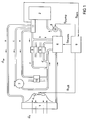
- the coolant circuit shown in FIG. 1 for an internal combustion engine 2 of a motor vehicle consists of several line branches a to f, the opening cross sections of which are controlled by a temperature-dependent valve 6 (thermostat).
- the direction of rotation of the coolant flow, which is driven by the coolant pump 3, is indicated by arrows.
- the line branch a is guided via a cooler module 1 for cooling the coolant emerging from the internal combustion engine 2. Air is drawn in from outside the motor vehicle by the fan 4 arranged behind the radiator module 1. When flowing through the cooler module 1, a heat exchange takes place between the air flow ⁇ l adjustable by the fan 4 and the coolant flow ⁇ w .
- a line branch b is provided, the cross section of which can be controlled by the temperature-dependent valve 6 in order to influence the coolant temperature.
- the line branch c has an expansion tank 7 and serves to regulate the pressure in the entire coolant circuit.
- a heat exchanger 8 for the interior heating of the motor vehicle and a cooler 9 and 10 for cooling the engine oil and the transmission oil are arranged in the additional line branches d to f. These line branches d to f are optional.
- the corresponding cooling or heating functions can also be solved in other ways.
- the coolant circuit includes a control unit 5, for example the control unit of the internal combustion engine, which receives the output signal S sen of a coolant temperature ⁇ w as an input signal, temperature sensor 11 which is detected at the engine outlet and, via the output signals S pump , S air and S therm, both the speed of the Coolant pump 3 and the fan 4 and the temperature-dependent valve 6 controls.
- a control unit 5 for example the control unit of the internal combustion engine, which receives the output signal S sen of a coolant temperature ⁇ w as an input signal, temperature sensor 11 which is detected at the engine outlet and, via the output signals S pump , S air and S therm, both the speed of the Coolant pump 3 and the fan 4 and the temperature-dependent valve 6 controls.
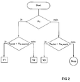
- FIGS. 2 to 4 show flow diagrams of this control method for explanation.
- the warm-up V1 of the internal combustion engine As illustrated in FIG. 2, three cases are distinguished in the method according to the invention; the warm-up V1 of the internal combustion engine, the driving mode V2 at the operating temperature of the coolant and the run-on V3.
- the first step A1 it is checked whether the internal combustion engine 2 was started., This is the case, a comparison is made of the coolant temperature ⁇ w, (output signal S sen of the temperature sensor 11) at the engine outlet to a termination of the warm-up phase ⁇ V1 characterizing temperature limit value w , warm. At a coolant temperature ⁇ w, below this temperature limit, warm-up V1 is detected. If the coolant temperature ⁇ w, the temperature limit ⁇ w, warml has been reached, the coolant circuit is controlled according to the algorithm for driving mode V2 at operating temperature.
- the coolant circuit is controlled using an algorithm for the run-on V3. If the coolant temperature ⁇ w is below the temperature limit ⁇ w, the control stops after the internal combustion engine 2 is restarted.
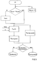
- the coolant temperature ⁇ w is compared in a first method step , is at the engine outlet with a coolant start temperature ⁇ w, start . If the coolant temperature is below the coolant start value ⁇ w, start , the coolant pump 3 starts with a delay of the time period t start in order to keep the heat flow from components of the internal combustion engine 2 into the coolant as low as possible and thus to achieve a faster heating of the components .
- the coolant flow ⁇ w generated by the coolant pump 3 is continuously increased until, for the first time, the minimum coolant flow ⁇ w , min for maintaining the differential temperature setpoint ⁇ w, Mot, should between engine and outlet is reached.
- the control signal S pump, min for the coolant pump 3 is calculated in the control unit 5 from the minimum coolant flow ⁇ w, min .
- the coolant pump 3 is regulated to maintain the differential temperature setpoint ⁇ w, Mot, coolant with a control signal S pump, warml .
- the differential temperature actual value ⁇ w, Mot, required for the control results from the heat flow Q ⁇ Mot from the internal combustion engine into the coolant, which in turn is calculated from the current coolant flow ⁇ w , the current engine load L Mot and the engine speed n.
- the heat flow Q ⁇ Mot is preferably stored as a map in the control unit 5 for the special internal combustion engine 2.
- the reaction of the coolant pump 3 to short-term engine load and speed changes should be prevented. Since, due to the thermal inertia of the internal combustion engine 2, brief changes in the engine load L Mot and the engine speed n play no role for the heat flow Q ⁇ Mot in the coolant, carrying the speed of the coolant pump 3 would represent unnecessary energy consumption.
- the control signal S pump for the coolant pump is therefore assigned a dynamic transmission behavior, the time constant T stg of which is selected such that the time behavior of the coolant pump roughly corresponds to the behavior of the heat flow Q ⁇ Mot from the internal combustion engine into the coolant. It follows that the speed change of the coolant pump 3 follows the change in the heat flow Qestr Mot in the coolant.
- the blower 4 is not activated during the warm-up phase V1, ie no airflow ⁇ l is generated by the cooler module 1.
- the warm-up phase V1 has ended when the current coolant temperature ⁇ w, the temperature limit value den w, warml is reached for the first time.
- the coolant temperature is also controlled as a function of a temperature setpoint ⁇ w, according to the algorithm for driving mode V2 at operating temperature instead.
- the temperature setpoint ⁇ w, set is first calculated. For this purpose, there is a map in the control unit 5 in which the optimum temperature setpoint ⁇ w, for the specified engine temperature with variable engine load L Mot , engine speed n and coolant flow ⁇ w , is stored.
- the control temperature ⁇ w, therm for the temperature-dependent valve 6 results, from which the control signal S therm for the temperature-dependent valve 6 is determined.
- the valve 6 regulates the coolant temperature ⁇ w via the coolant flow conditions between the line branch a led via the cooler module 1 and the line branch b.
- the minimum coolant flow ⁇ w, min the required minimum speed of the coolant pump 3 and thus the optimal control signal S pump, min . If the current coolant temperature exceeds ⁇ w, the temperature setpoint is ⁇ w, and if the engine outlet is hot by a difference value ⁇ w, either the speed of the coolant pump 3 and thus the coolant flow ⁇ w or the speed of the fan 4 and thus the air flow ⁇ l increased. Whether it makes more sense in terms of energy to change the speed of the coolant pump 3 or of the blower 4 is determined by comparing their efficiency for heat dissipation at the cooler module 1 over time.
- the coolant circuit is simultaneously used to cool the engine oil via a cooler 9, the current oil temperature ⁇ oil can be monitored with a sensor (not shown). Exceeds the current oil temperature ⁇ oil has a temperature limit value ⁇ oil, cross so gradually the coolant temperature ⁇ w is reduced until the oil temperature ⁇ oil drops below this limit temperature value again. The coolant temperature required for the selected engine temperature is then set again.
- the dynamic behavior of the control in the event of brief changes in the engine load L Mot and the engine speed n is different for compliance with the differential temperature setpoint ⁇ w, Mot, setpoint and the temperature setpoint ⁇ w, setpoint.
- the control according to the differential temperature setpoint ⁇ w, Mot, soll corresponds in dynamics to that of warm-up V1.
- the regulation according to the temperature setpoint ⁇ w should be done faster by varying the valve current S term and the speeds of the coolant pump 3 and blower 4.
- a compromise must be found between an energetic optimum and the temperature constancy of the components of the internal combustion engine 2. For energy purposes, it makes sense to allow brief temperature changes in the components, such as those that occur during the overtaking process.
Landscapes
- Engineering & Computer Science (AREA)
- Chemical & Material Sciences (AREA)
- Combustion & Propulsion (AREA)
- Mechanical Engineering (AREA)
- General Engineering & Computer Science (AREA)
- Combined Controls Of Internal Combustion Engines (AREA)
- Air-Conditioning For Vehicles (AREA)
Applications Claiming Priority (2)
| Application Number | Priority Date | Filing Date | Title |
|---|---|---|---|
| DE19508104A DE19508104C2 (de) | 1995-03-08 | 1995-03-08 | Verfahren zur Regelung eines Kühlkreislaufes eines Verbrennungskraftmotors |
| DE19508104 | 1995-03-08 |
Publications (2)
| Publication Number | Publication Date |
|---|---|
| EP0731260A1 true EP0731260A1 (fr) | 1996-09-11 |
| EP0731260B1 EP0731260B1 (fr) | 2000-06-07 |
Family
ID=7755955
Family Applications (1)
| Application Number | Title | Priority Date | Filing Date |
|---|---|---|---|
| EP96100636A Expired - Lifetime EP0731260B1 (fr) | 1995-03-08 | 1996-01-18 | Procédé de commande d'un circuit de refroidissement d'un moteur à combustion interne |
Country Status (4)
| Country | Link |
|---|---|
| US (1) | US5724924A (fr) |
| EP (1) | EP0731260B1 (fr) |
| DE (2) | DE19508104C2 (fr) |
| ES (1) | ES2148598T3 (fr) |
Cited By (5)
| Publication number | Priority date | Publication date | Assignee | Title |
|---|---|---|---|---|
| FR2752016A1 (fr) * | 1996-07-31 | 1998-02-06 | Renault | Dispositif de refroidissement d'un moteur a combustion interne |
| EP0952315A1 (fr) * | 1998-04-24 | 1999-10-27 | GATE S.p.A. | Système de commande pour minimiser la consommation d'énergie dans un système de refroidissement d'un moteur à combustion interne |
| WO2000015952A1 (fr) * | 1998-09-11 | 2000-03-23 | Müller-BBM GmbH | Systeme de refroidissement, notamment pour vehicules ferroviaires |
| WO2001012964A1 (fr) * | 1999-08-18 | 2001-02-22 | Robert Bosch Gmbh | Procede de regulation de la temperature de l'agent refrigerant d'un moteur a combustion interne a l'aide d'une pompe de fluide refrigerant a commande electrique |
| EP3211194A1 (fr) * | 2011-12-01 | 2017-08-30 | Paccar Inc | Systèmes et procédés de commande d'une pompe a eau à vitesse variable |
Families Citing this family (46)
| Publication number | Priority date | Publication date | Assignee | Title |
|---|---|---|---|---|
| US5660149A (en) * | 1995-12-21 | 1997-08-26 | Siemens Electric Limited | Total cooling assembly for I.C. engine-powered vehicles |
| JP3473398B2 (ja) * | 1998-05-01 | 2003-12-02 | 株式会社日立製作所 | 地図応用システムおよび地図表示制御方法 |
| US6178928B1 (en) | 1998-06-17 | 2001-01-30 | Siemens Canada Limited | Internal combustion engine total cooling control system |
| US6142110A (en) * | 1999-01-21 | 2000-11-07 | Caterpillar Inc. | Engine having hydraulic and fan drive systems using a single high pressure pump |
| FR2793842B1 (fr) * | 1999-05-17 | 2002-06-14 | Valeo Thermique Moteur Sa | Dispositif electronique de regulation du refroidissement d'un moteur thermique de vehicule automobile |
| FR2796987B1 (fr) | 1999-07-30 | 2002-09-20 | Valeo Thermique Moteur Sa | Dispositif de regulation du refroidissement d'un moteur thermique de vehicule automobile |
| US6394044B1 (en) * | 2000-01-31 | 2002-05-28 | General Electric Company | Locomotive engine temperature control |
| FR2808304B1 (fr) * | 2000-04-27 | 2002-11-15 | Valeo Thermique Moteur Sa | Dispositif de refroidissement a l'arret d'un moteur thermique de vehicule automobile |
| US6374780B1 (en) | 2000-07-07 | 2002-04-23 | Visteon Global Technologies, Inc. | Electric waterpump, fluid control valve and electric cooling fan strategy |
| KR100348588B1 (ko) * | 2000-07-07 | 2002-08-14 | 국방과학연구소 | 차량용 냉각장치 |
| US6739290B2 (en) * | 2001-03-06 | 2004-05-25 | Calsonic Kansei Corporation | Cooling system for water-cooled internal combustion engine and control method applicable to cooling system therefor |
| DE10123444B4 (de) * | 2001-05-14 | 2006-11-09 | Siemens Ag | Regelanlage zum Regeln der Kühlmitteltemperatur einer Brennkraftmaschine |
| DE10153486A1 (de) * | 2001-10-22 | 2003-05-08 | Bosch Gmbh Robert | Verfahren, Computerprogramm und Steuer- und/oder Regelgerät zum Betreiben einer Brennkraftmaschine, sowie Brennkraftmaschine |
| DE10154091A1 (de) | 2001-11-02 | 2003-05-15 | Bayerische Motoren Werke Ag | Verfahren und Vorrichtung zur Regelung eines Kühlsystems einer Verbrennungskraftmaschine |
| JP4023176B2 (ja) * | 2002-02-13 | 2007-12-19 | トヨタ自動車株式会社 | 内燃機関の冷却装置 |
| DE10224063A1 (de) | 2002-05-31 | 2003-12-11 | Daimler Chrysler Ag | Verfahren zur Wärmeregulierung einer Brennkraftmaschine für Fahrzeuge |
| US6802335B2 (en) * | 2003-01-23 | 2004-10-12 | Masco Corporation Of Indiana | Faucet handle retainer |
| DE102004008170B4 (de) * | 2004-02-19 | 2015-04-30 | Robert Bosch Gmbh | Verfahren und Vorrichtung zur Steuerung des Kühlkreislaufs einer Brennkraftmaschine |
| FR2869355B1 (fr) * | 2004-04-22 | 2010-09-10 | Valeo Thermique Moteur Sa | Procede de regulation thermique par modele predictif pour un circuit de refroidissement d'un moteur |
| JP4631652B2 (ja) * | 2005-10-25 | 2011-02-16 | トヨタ自動車株式会社 | 冷却システムおよびその制御方法並びに自動車 |
| US7421983B1 (en) * | 2007-03-26 | 2008-09-09 | Brunswick Corporation | Marine propulsion system having a cooling system that utilizes nucleate boiling |
| DE102008000907A1 (de) | 2008-04-01 | 2009-10-08 | Robert Bosch Gmbh | Magnetventil mit mehrteiligem Anker ohne Ankerführung |
| DE102009001706A1 (de) | 2009-03-20 | 2010-09-23 | Robert Bosch Gmbh | Restluftspaltscheibe |
| US8215381B2 (en) * | 2009-04-10 | 2012-07-10 | Ford Global Technologies, Llc | Method for controlling heat exchanger fluid flow |
| DE102009026522A1 (de) | 2009-05-28 | 2010-12-02 | Robert Bosch Gmbh | Magnetventil ohne Ankerrückstellzeit |
| US8452459B2 (en) * | 2009-08-31 | 2013-05-28 | Fisher-Rosemount Systems, Inc. | Heat exchange network heat recovery optimization in a process plant |
| US20120067332A1 (en) * | 2010-09-17 | 2012-03-22 | Gm Global Technology Operations, Inc. | Integrated exhaust gas recirculation and charge cooling system |
| US9341105B2 (en) | 2012-03-30 | 2016-05-17 | Ford Global Technologies, Llc | Engine cooling system control |
| US9022647B2 (en) | 2012-03-30 | 2015-05-05 | Ford Global Technologies, Llc | Engine cooling system control |
| US8683854B2 (en) | 2012-03-30 | 2014-04-01 | Ford Global Technologies, Llc | Engine cooling system control |
| US8689617B2 (en) | 2012-03-30 | 2014-04-08 | Ford Global Technologies, Llc | Engine cooling system control |
| US8922033B2 (en) | 2013-03-04 | 2014-12-30 | General Electric Company | System for cooling power generation system |
| US9523306B2 (en) * | 2014-05-13 | 2016-12-20 | International Engine Intellectual Property Company, Llc. | Engine cooling fan control strategy |
| JP6123741B2 (ja) * | 2014-06-20 | 2017-05-10 | トヨタ自動車株式会社 | 冷却器 |
| US10480391B2 (en) * | 2014-08-13 | 2019-11-19 | GM Global Technology Operations LLC | Coolant control systems and methods to prevent coolant boiling |
| US9957875B2 (en) | 2014-08-13 | 2018-05-01 | GM Global Technology Operations LLC | Coolant pump control systems and methods for backpressure compensation |
| DE102015006303A1 (de) * | 2015-05-16 | 2016-11-17 | GM Global Technology Operations LLC (n. d. Ges. d. Staates Delaware) | Kühlsystem mit einer Kühlmittelpumpe für eine Brennkraftmaschine |
| DE102015006302A1 (de) | 2015-05-16 | 2016-11-17 | GM Global Technology Operations LLC (n. d. Ges. d. Staates Delaware) | Kühlsystem mit einer Kühlmittelpumpe für eine Brennkraftmaschine |
| KR101694012B1 (ko) * | 2015-06-18 | 2017-01-06 | 현대자동차주식회사 | 차량의 워터펌프 제어방법 및 제어장치 |
| JP6384409B2 (ja) * | 2015-06-24 | 2018-09-05 | トヨタ自動車株式会社 | 排熱回収器構造 |
| US10006335B2 (en) * | 2015-11-04 | 2018-06-26 | GM Global Technology Operations LLC | Coolant temperature correction systems and methods |
| US10215080B2 (en) | 2016-11-01 | 2019-02-26 | Ford Global Technologies, Llc | Systems and methods for rapid engine coolant warmup |
| JP6863228B2 (ja) * | 2017-10-26 | 2021-04-21 | トヨタ自動車株式会社 | 冷却装置 |
| CN108644003A (zh) * | 2018-07-18 | 2018-10-12 | 龙城电装(常州)有限公司 | 一种水冷发动机智能热管理系统 |
| CN111520227B (zh) * | 2020-05-08 | 2021-03-16 | 蜂巢动力系统(江苏)有限公司 | 一种发动机电子水泵的控制方法 |
| JP7626029B2 (ja) * | 2021-11-05 | 2025-02-04 | トヨタ自動車株式会社 | 制御装置 |
Citations (4)
| Publication number | Priority date | Publication date | Assignee | Title |
|---|---|---|---|---|
| FR2384106A1 (fr) * | 1977-03-16 | 1978-10-13 | Sev Marchal | Dispositif de refroidissement pour moteur a combustion interne |
| JPS5874824A (ja) * | 1981-10-29 | 1983-05-06 | Nissan Motor Co Ltd | 機関の冷却装置 |
| WO1984000578A1 (fr) * | 1982-08-05 | 1984-02-16 | Marchal Equip Auto | Dispositif de refroidissement d'un moteur a combustion interne |
| EP0557113A2 (fr) * | 1992-02-19 | 1993-08-25 | Honda Giken Kogyo Kabushiki Kaisha | Système de refroidissement pour moteur |
Family Cites Families (5)
| Publication number | Priority date | Publication date | Assignee | Title |
|---|---|---|---|---|
| DE3024209A1 (de) * | 1979-07-02 | 1981-01-22 | Guenter Dr Rinnerthaler | Fluessigkeitskuehlung fuer verbrennungsmotoren |
| FR2495687B1 (fr) * | 1980-12-10 | 1985-11-29 | Peugeot Aciers Et Outillage | Circuit de securite pour dispositif de regulation de la temperature d'un fluide de refroidissement d'un moteur a combustion interne |
| FR2554165B1 (fr) * | 1983-10-28 | 1988-01-15 | Marchal Equip Auto | Procede de regulation de la temperature du liquide de refroidissement d'un moteur a combustion interne et dispositif pour sa mise en oeuvre |
| DE3810174C2 (de) * | 1988-03-25 | 1996-09-19 | Hella Kg Hueck & Co | Einrichtung zur Regelung der Kühlmitteltemperatur einer Brennkraftmaschine, insbesondere in Kraftfahrzeugen |
| DE4238364A1 (de) * | 1992-11-13 | 1994-05-26 | Behr Gmbh & Co | Einrichtung zum Kühlen von Antriebskomponenten und zum Heizen eines Fahrgastraumes eines Elektrofahrzeugs |
-
1995
- 1995-03-08 DE DE19508104A patent/DE19508104C2/de not_active Expired - Fee Related
-
1996
- 1996-01-18 DE DE59605375T patent/DE59605375D1/de not_active Expired - Lifetime
- 1996-01-18 EP EP96100636A patent/EP0731260B1/fr not_active Expired - Lifetime
- 1996-01-18 ES ES96100636T patent/ES2148598T3/es not_active Expired - Lifetime
- 1996-03-06 US US08/611,344 patent/US5724924A/en not_active Expired - Fee Related
Patent Citations (4)
| Publication number | Priority date | Publication date | Assignee | Title |
|---|---|---|---|---|
| FR2384106A1 (fr) * | 1977-03-16 | 1978-10-13 | Sev Marchal | Dispositif de refroidissement pour moteur a combustion interne |
| JPS5874824A (ja) * | 1981-10-29 | 1983-05-06 | Nissan Motor Co Ltd | 機関の冷却装置 |
| WO1984000578A1 (fr) * | 1982-08-05 | 1984-02-16 | Marchal Equip Auto | Dispositif de refroidissement d'un moteur a combustion interne |
| EP0557113A2 (fr) * | 1992-02-19 | 1993-08-25 | Honda Giken Kogyo Kabushiki Kaisha | Système de refroidissement pour moteur |
Non-Patent Citations (1)
| Title |
|---|
| PATENT ABSTRACTS OF JAPAN vol. 007, no. 169 (M - 231) 26 July 1958 (1958-07-26) * |
Cited By (10)
| Publication number | Priority date | Publication date | Assignee | Title |
|---|---|---|---|---|
| FR2752016A1 (fr) * | 1996-07-31 | 1998-02-06 | Renault | Dispositif de refroidissement d'un moteur a combustion interne |
| EP0952315A1 (fr) * | 1998-04-24 | 1999-10-27 | GATE S.p.A. | Système de commande pour minimiser la consommation d'énergie dans un système de refroidissement d'un moteur à combustion interne |
| US6213061B1 (en) | 1998-04-24 | 2001-04-10 | Gate S.P.A. | Control system for minimizing electricity consumption in a cooling system of an internal combustion engine |
| WO2000015952A1 (fr) * | 1998-09-11 | 2000-03-23 | Müller-BBM GmbH | Systeme de refroidissement, notamment pour vehicules ferroviaires |
| WO2001012964A1 (fr) * | 1999-08-18 | 2001-02-22 | Robert Bosch Gmbh | Procede de regulation de la temperature de l'agent refrigerant d'un moteur a combustion interne a l'aide d'une pompe de fluide refrigerant a commande electrique |
| US6662761B1 (en) | 1999-08-18 | 2003-12-16 | Robert Bosch Gmbh | Method for regulating the temperature of the coolant in an internal combustion engine using an electrically operated coolant pump |
| EP3211194A1 (fr) * | 2011-12-01 | 2017-08-30 | Paccar Inc | Systèmes et procédés de commande d'une pompe a eau à vitesse variable |
| US10119453B2 (en) | 2011-12-01 | 2018-11-06 | Paccar Inc | Systems and methods for controlling a variable speed water pump |
| AU2017201730B2 (en) * | 2011-12-01 | 2019-03-28 | Paccar Inc. | Systems and methods for controlling a variable speed water pump |
| US10914227B2 (en) | 2011-12-01 | 2021-02-09 | Paccar Inc | Systems and methods for controlling a variable speed water pump |
Also Published As
| Publication number | Publication date |
|---|---|
| EP0731260B1 (fr) | 2000-06-07 |
| DE59605375D1 (de) | 2000-07-13 |
| ES2148598T3 (es) | 2000-10-16 |
| US5724924A (en) | 1998-03-10 |
| DE19508104A1 (de) | 1996-09-12 |
| DE19508104C2 (de) | 2000-05-25 |
Similar Documents
| Publication | Publication Date | Title |
|---|---|---|
| EP0731260B1 (fr) | Procédé de commande d'un circuit de refroidissement d'un moteur à combustion interne | |
| EP0731261B1 (fr) | Procédé de commande d'un circuit de refroidissement d'un moteur à combustion interne, notamment pour véhicules automobiles | |
| DE60307932T2 (de) | Vorrichtung und Verfahren zum Kontrollieren eines elektromotorisch angetriebenen Gebläses eines Kraftfahrzeuges | |
| EP1509687B1 (fr) | Procede de regulation thermique de moteur a combustion interne pour vehicules | |
| DE60317125T2 (de) | Kühlungsanlage für eine Brennkraftmaschine | |
| DE19719792B4 (de) | Verfahren und Vorrichtung zur Regulierung der Temperatur eines Mediums | |
| DE3601532C2 (fr) | ||
| EP0372171B1 (fr) | Système de conditionnement d'air | |
| DE19540591C2 (de) | Verfahren zur Regelung der Volumenstromverteilung in einem Kühlmittelkreislauf für Kraftfahrzeuge mit Motor und Vorrichtung zur Durchführung des Verfahrens | |
| DE10134678A1 (de) | Vorrichtung zum Kühlen und Heizen eines Kraftfahrzeuges | |
| DE2806708C2 (de) | Vorrichtung zur Temperaturregelung eines Kühlsystems einer Brennkraftmaschine, insbesondere für Kraftfahrzeuge | |
| DE102018127409A1 (de) | Strategie/verfahren zur regelung eines gleichungsbasierten kühlsystems | |
| DE102013206499A1 (de) | Vorrichtung und Verfahren zum Steuern der Kühlmitteltemperatur eines Brennstoffzellensystems | |
| DE10016435B4 (de) | Lüftungseinrichtung für ein landwirtschaftliches Fahrzeug | |
| DE102010009279A1 (de) | Zusatzheizpumpensteuerung | |
| EP0777585B1 (fr) | Echangeur de chaleur pour automobile | |
| EP1399656B1 (fr) | Procede de surveillance d'un circuit de refroidissement dans un moteur a combustion interne | |
| DE19818030C2 (de) | Verfahren und Vorrichtung zum Betreiben eines Kühlmittelkreises einer Brennkraftmaschine | |
| DE10260260B4 (de) | Maschinenkühlsystem | |
| DE60013082T2 (de) | Kühlungsregelungsvorrichtung einer Fahrzeugbrennkraftmaschine während eines Heissstarts | |
| DE19743828A1 (de) | Verfahren zum Betrieb einer Klimaanlage mit Kompressor und Kondensatorgebläse | |
| EP1940636B1 (fr) | Dispositif de commande d'un appareil de chauffage independant du moteur, systeme de chauffage et procede de commande d'un appareil de chauffage independant du moteur | |
| EP1140532B1 (fr) | Chauffage pour habitacle de vehicule | |
| DE60214515T2 (de) | Einrichtung und verfahren zur kühlung einer steuervorrichtung einer brennkraftmaschine | |
| EP1523612A1 (fr) | Procede et dispositif de reglage de la temperature d'un fluide de refroidissement d'un moteur a combustion interne |
Legal Events
| Date | Code | Title | Description |
|---|---|---|---|
| PUAI | Public reference made under article 153(3) epc to a published international application that has entered the european phase |
Free format text: ORIGINAL CODE: 0009012 |
|
| AK | Designated contracting states |
Kind code of ref document: A1 Designated state(s): DE ES FR GB |
|
| 17P | Request for examination filed |
Effective date: 19970311 |
|
| 17Q | First examination report despatched |
Effective date: 19990203 |
|
| GRAG | Despatch of communication of intention to grant |
Free format text: ORIGINAL CODE: EPIDOS AGRA |
|
| GRAG | Despatch of communication of intention to grant |
Free format text: ORIGINAL CODE: EPIDOS AGRA |
|
| GRAH | Despatch of communication of intention to grant a patent |
Free format text: ORIGINAL CODE: EPIDOS IGRA |
|
| GRAH | Despatch of communication of intention to grant a patent |
Free format text: ORIGINAL CODE: EPIDOS IGRA |
|
| GRAA | (expected) grant |
Free format text: ORIGINAL CODE: 0009210 |
|
| AK | Designated contracting states |
Kind code of ref document: B1 Designated state(s): DE ES FR GB |
|
| REF | Corresponds to: |
Ref document number: 59605375 Country of ref document: DE Date of ref document: 20000713 |
|
| ET | Fr: translation filed | ||
| GBT | Gb: translation of ep patent filed (gb section 77(6)(a)/1977) |
Effective date: 20000905 |
|
| REG | Reference to a national code |
Ref country code: ES Ref legal event code: FG2A Ref document number: 2148598 Country of ref document: ES Kind code of ref document: T3 |
|
| PLBE | No opposition filed within time limit |
Free format text: ORIGINAL CODE: 0009261 |
|
| STAA | Information on the status of an ep patent application or granted ep patent |
Free format text: STATUS: NO OPPOSITION FILED WITHIN TIME LIMIT |
|
| 26N | No opposition filed | ||
| REG | Reference to a national code |
Ref country code: GB Ref legal event code: IF02 |
|
| PGFP | Annual fee paid to national office [announced via postgrant information from national office to epo] |
Ref country code: GB Payment date: 20031231 Year of fee payment: 9 |
|
| PGFP | Annual fee paid to national office [announced via postgrant information from national office to epo] |
Ref country code: FR Payment date: 20040122 Year of fee payment: 9 |
|
| PGFP | Annual fee paid to national office [announced via postgrant information from national office to epo] |
Ref country code: ES Payment date: 20040129 Year of fee payment: 9 |
|
| PG25 | Lapsed in a contracting state [announced via postgrant information from national office to epo] |
Ref country code: GB Free format text: LAPSE BECAUSE OF NON-PAYMENT OF DUE FEES Effective date: 20050118 |
|
| PG25 | Lapsed in a contracting state [announced via postgrant information from national office to epo] |
Ref country code: ES Free format text: LAPSE BECAUSE OF NON-PAYMENT OF DUE FEES Effective date: 20050119 |
|
| GBPC | Gb: european patent ceased through non-payment of renewal fee |
Effective date: 20050118 |
|
| PG25 | Lapsed in a contracting state [announced via postgrant information from national office to epo] |
Ref country code: FR Free format text: LAPSE BECAUSE OF NON-PAYMENT OF DUE FEES Effective date: 20050930 |
|
| REG | Reference to a national code |
Ref country code: FR Ref legal event code: ST |
|
| REG | Reference to a national code |
Ref country code: ES Ref legal event code: FD2A Effective date: 20050119 |
|
| PGFP | Annual fee paid to national office [announced via postgrant information from national office to epo] |
Ref country code: DE Payment date: 20120131 Year of fee payment: 17 |
|
| PG25 | Lapsed in a contracting state [announced via postgrant information from national office to epo] |
Ref country code: DE Free format text: LAPSE BECAUSE OF NON-PAYMENT OF DUE FEES Effective date: 20130801 |
|
| REG | Reference to a national code |
Ref country code: DE Ref legal event code: R119 Ref document number: 59605375 Country of ref document: DE Effective date: 20130801 |