EP0731264A2 - Système d'admission pour un moteur à combustion interne du type à deux temps - Google Patents
Système d'admission pour un moteur à combustion interne du type à deux temps Download PDFInfo
- Publication number
- EP0731264A2 EP0731264A2 EP96101418A EP96101418A EP0731264A2 EP 0731264 A2 EP0731264 A2 EP 0731264A2 EP 96101418 A EP96101418 A EP 96101418A EP 96101418 A EP96101418 A EP 96101418A EP 0731264 A2 EP0731264 A2 EP 0731264A2
- Authority
- EP
- European Patent Office
- Prior art keywords
- inflow
- cylinder
- purge air
- intake system
- inlet
- Prior art date
- Legal status (The legal status is an assumption and is not a legal conclusion. Google has not performed a legal analysis and makes no representation as to the accuracy of the status listed.)
- Granted
Links
- 238000002485 combustion reaction Methods 0.000 title claims abstract description 18
- 230000002000 scavenging effect Effects 0.000 claims abstract description 13
- 238000010926 purge Methods 0.000 claims description 49
- 230000001105 regulatory effect Effects 0.000 claims description 21
- 230000014759 maintenance of location Effects 0.000 claims description 4
- 230000001276 controlling effect Effects 0.000 claims description 2
- 238000007789 sealing Methods 0.000 claims description 2
- 239000003344 environmental pollutant Substances 0.000 abstract description 4
- 239000000446 fuel Substances 0.000 abstract description 4
- 231100000719 pollutant Toxicity 0.000 abstract description 4
- 230000033228 biological regulation Effects 0.000 description 4
- 238000010276 construction Methods 0.000 description 3
- 239000002184 metal Substances 0.000 description 3
- 238000001816 cooling Methods 0.000 description 2
- 238000011010 flushing procedure Methods 0.000 description 2
- 230000015572 biosynthetic process Effects 0.000 description 1
- 230000006835 compression Effects 0.000 description 1
- 238000007906 compression Methods 0.000 description 1
- 230000001419 dependent effect Effects 0.000 description 1
- 239000000203 mixture Substances 0.000 description 1
- 238000011144 upstream manufacturing Methods 0.000 description 1
Images

Classifications
-
- F—MECHANICAL ENGINEERING; LIGHTING; HEATING; WEAPONS; BLASTING
- F02—COMBUSTION ENGINES; HOT-GAS OR COMBUSTION-PRODUCT ENGINE PLANTS
- F02B—INTERNAL-COMBUSTION PISTON ENGINES; COMBUSTION ENGINES IN GENERAL
- F02B25/00—Engines characterised by using fresh charge for scavenging cylinders
- F02B25/02—Engines characterised by using fresh charge for scavenging cylinders using unidirectional scavenging
- F02B25/04—Engines having ports both in cylinder head and in cylinder wall near bottom of piston stroke
-
- F—MECHANICAL ENGINEERING; LIGHTING; HEATING; WEAPONS; BLASTING
- F02—COMBUSTION ENGINES; HOT-GAS OR COMBUSTION-PRODUCT ENGINE PLANTS
- F02F—CYLINDERS, PISTONS OR CASINGS, FOR COMBUSTION ENGINES; ARRANGEMENTS OF SEALINGS IN COMBUSTION ENGINES
- F02F1/00—Cylinders; Cylinder heads
- F02F1/18—Other cylinders
- F02F1/22—Other cylinders characterised by having ports in cylinder wall for scavenging or charging
-
- F—MECHANICAL ENGINEERING; LIGHTING; HEATING; WEAPONS; BLASTING
- F02—COMBUSTION ENGINES; HOT-GAS OR COMBUSTION-PRODUCT ENGINE PLANTS
- F02B—INTERNAL-COMBUSTION PISTON ENGINES; COMBUSTION ENGINES IN GENERAL
- F02B75/00—Other engines
- F02B75/02—Engines characterised by their cycles, e.g. six-stroke
- F02B2075/022—Engines characterised by their cycles, e.g. six-stroke having less than six strokes per cycle
- F02B2075/025—Engines characterised by their cycles, e.g. six-stroke having less than six strokes per cycle two
-
- F—MECHANICAL ENGINEERING; LIGHTING; HEATING; WEAPONS; BLASTING
- F02—COMBUSTION ENGINES; HOT-GAS OR COMBUSTION-PRODUCT ENGINE PLANTS
- F02B—INTERNAL-COMBUSTION PISTON ENGINES; COMBUSTION ENGINES IN GENERAL
- F02B2275/00—Other engines, components or details, not provided for in other groups of this subclass
- F02B2275/48—Tumble motion in gas movement in cylinder
-
- Y—GENERAL TAGGING OF NEW TECHNOLOGICAL DEVELOPMENTS; GENERAL TAGGING OF CROSS-SECTIONAL TECHNOLOGIES SPANNING OVER SEVERAL SECTIONS OF THE IPC; TECHNICAL SUBJECTS COVERED BY FORMER USPC CROSS-REFERENCE ART COLLECTIONS [XRACs] AND DIGESTS
- Y02—TECHNOLOGIES OR APPLICATIONS FOR MITIGATION OR ADAPTATION AGAINST CLIMATE CHANGE
- Y02T—CLIMATE CHANGE MITIGATION TECHNOLOGIES RELATED TO TRANSPORTATION
- Y02T10/00—Road transport of goods or passengers
- Y02T10/10—Internal combustion engine [ICE] based vehicles
- Y02T10/12—Improving ICE efficiencies
Definitions
- the invention relates to an intake system for a two-stroke internal combustion engine according to the preamble of claim 1.
- the internal combustion engine comprises a working cylinder together with a cylinder running surface, with purging air slots distributed in its wall on the circumference of the cylinder and arranged in two inlet rows one above the other.
- the opening of the scavenging air slots on the cylinder tread side and the supply of scavenging air into the cylinder is controlled by a piston which can reciprocate in the latter.
- the internal combustion engine has an additional blower which is separate from the working cylinder / piston assembly and by means of which fresh air can be conveyed into the working cylinder through two superimposed inlet rows of the purge air slots.
- the invention has for its object to provide a generic intake system for a two-stroke internal combustion engine in such a way that with the purge air openings as variable a regulation of swirl and volume flow of the fresh air supplied and thus a substantial reduction in fuel consumption and a significant reduction in pollutant emissions of the internal combustion engine can be achieved .
- An advantage of the intake system according to the invention is that by regulating the inflow of fresh air according to the invention when the intake openings are opened by the piston (for example intake slots, bores or elongated holes) there is a multitude of possible variations depending only on the engine operating point.
- the swirl can be regulated as a function of the change in volume flow or at a constant volume flow, the engine operability in suction operation can be better guaranteed and the flushing pressure requirement can be reduced.
- the variable regulation of the swirl and the volume flow of the fresh air supplied can achieve a significant reduction in fuel consumption and a considerable reduction in pollutant emissions from the internal combustion engine.
- variable exhaust gas retention can be implemented without any disadvantages in the swirl, and an influence on the axial speed distribution can be taken as a boundary condition on the cylinder internal flow in the compression and mixture formation phase. It is particularly advantageous if the openings of the lower of the two inlet rows open radially and the openings of the upper inlet row tangentially into the cylinder, since the control times are longer for the upper inlet row than for the lower inlet row and thus an increased basic twist on the fresh air charge which flows through the upper inlet row can be given.
- the embodiment of the invention according to claim 3 offers further flexibility with regard to the possibilities of influencing the fresh air inflow. For example, two inlet rows with purge air openings opening into the cylinder at different angles can be provided, so that a different swirl of the inflowing fresh air can be achieved with each inlet row.
- the embodiment according to claim 4 is a preferred construction of the invention.
- the purging air openings of each inlet row are bores arranged on the circumference of the cylinder, the bores of the upper inlet row being tangential and the bores of the lower inlet row being only slightly deflected radially or radially from the radial direction (slightly tangential) to the cylinder.
- a particularly variable regulation of the swirl and the volume flow of the fresh air flow is possible due to the means arranged at the individual purge air openings for influencing the swirl and for regulating the respective inflow cross section of the individual purge air openings.
- the volume flow and the swirl of the fresh air supplied can be regulated, for example, as a function of the engine operating point.
- the embodiment according to claim 7 is a particularly simple and inexpensive construction of the invention, in this embodiment, the inflow cross-section is largely controlled independently of the position of the piston.
- the embodiment of the invention according to claim 9 is a structurally particularly simple way to provide cooling of the thermally highly stressed upper piston edge and top land.
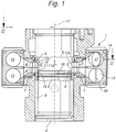
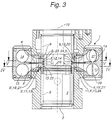
- FIG. 1 and 3 show in two exemplary embodiments a schematic sectional illustration of an intake system 1 of a two-stroke internal combustion engine (not shown in more detail) with a cylinder 2, a piston 3 and purge air channels 4, 4 'and purge air openings 5, 5'.
- the cut lies in a meridian plane of cylinder 2.
- the cylinder 2 has a cylinder running surface 8, the supply of purging air into the cylinder 2 via openings 9 of the purging air openings 5, 5 ′ on the cylinder running surface being controlled by the piston 3 which is reciprocable therein.
- the purge air openings 5, 5 ' viewed in the cylinder longitudinal axis 10, are arranged one above the other in two inlet rows 11 and 12, the inlet row 11 being assigned to an inflow plane 13 and the inlet row 12 being assigned to an inflow plane 14.
- the purge air openings 5 are the inlet row 12, and the purge air openings 5 'are assigned to the inlet row 11.
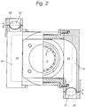
- the two inflow planes 13, 14 are arranged adjacent to one another and are separated from one another in terms of flow by a separating plane T (see FIGS. 1, 3 and 8), each inflow plane 13, 14 having its own control members 25, 26 and 27, 28 (e.g. Throttle valves, see Fig. 2).
- the parting plane T can comprise, for example, a metal or plastic plate (see FIGS. 1 and 3) which is fastened to a wall lying between the two channels 13, 14 and projects into an annular gap arranged in the cylinder crankcase up to a cylinder liner (cylinder 2) , so that two superimposed purge air channels 4 and 4 'are formed.
- the metal or plastic plate can be struck against a web that separates the two inlet rows 11 and 12 in the cylinder liner in the direction of the cylinder longitudinal axis, so that the parting plane T is formed by said wall, said metal or plastic plate and the web.
- the inlet row 11 and the inlet row 12 in the cylinder 2 are supplied with fresh charge (fresh air) via the inflow level 13. 1, the throttle valves 27 and 28 are shown in different opening positions, the throttle valve 27 being partially opened and the throttle valve 28 being shown fully open.
- the throttle valves 25-28 are adjusted in a manner known in principle via an electrical or mechanical actuator, not shown.
- Fig. 1 the flow-separated inflow planes 13, 14 open directly into the inlet rows 11, 12, the purge air openings 5,5 'of each inlet row 11, 12 being holes 11a, 12a arranged uniformly on the circumference of the cylinder 2 (see Fig. 8) .
- the purge air openings 5, 5 'of the inlet rows 11, 12 have a different inlet geometry such that, in order to influence an exhaust gas retention in the cylinder 2 in the inlet row 11, the inflow into the cylinder 2 takes place radially and in the inlet row 12 tangentially (the bores 11a of the inlet row 11 run radially and the bores 12a of the inlet rows 12 tangential to the cylinder 2).
- two or more inlet rows 11 and 12 arranged one above the other in the direction of the cylinder longitudinal axis 10 can also be provided in each inflow plane 13, 14.
- the arrangement of the bores 11a and 12a aligned radially and tangentially to the cylinder 2 is arbitrary.
- it is particularly advantageous with a view to minimizing exhaust gas retention in the cylinder if the openings 5 'of the lower of the two intake rows 11, 12 open radially and the openings 5 of the upper intake row 12 tangentially into the cylinder, since the timing for the upper intake row 12 are longer than for the lower inlet row 11 and thus an increased basic twist on the fresh air charge that flows through the upper inlet row 12 can be given.
- the bottom inlet row 11 of the purge air slots 5 defines an upper piston edge 16 of the piston 3 in its UT position.
- the piston 3 is shown in FIGS. 1 and 3 in the UT position.
- the UT position of the piston 3 with respect to the inlet rows 11, 12 is also shown schematically in FIG. 8.
- the two inflow planes 13 and 14, which are arranged one above the other and adjacent to one another and adjacent in the direction of the cylinder axis 10, are divided into two diametrically opposite inflow units 23 and 24, the inflow unit 23 each being half of the inflow planes separated in terms of flow 13 and 14 and the other inflow unit 24 each comprise the other half of the inflow levels 13 and 14.
- the inflow unit 23 (according to FIGS. 3 and 4) thus comprises the left half and the inflow unit 24 the right half of the inflow planes 13 and 14.
- FIG. 2 shows a section II - II of FIG. 1 with the two diametrically opposite inflow units 23 and 24.
- the same reference numerals are used for the same components from FIGS. 1 and 3.
- Each of the inflow units 23 and 24 has two control members (throttle valves) 25, 26 (inflow level 23) and 27, 28 (inflow level 24).
- the volume flow in each half of the inflow level 13, 14 of the inflow unit 23 can be regulated via a separate control element (throttle valve) 25 or 26.
- the volume flow in each half of the inflow plane 13, 14 of the inflow unit 24 can be regulated via a separate control member (throttle valve) 27 or 28.
- control elements 25-28 are controlled as a function of the engine operating point, for example via an engine map, each control element 25-28 being controllable independently of the other, so that the control elements 25-28 control the inflow of purge air to the inlet rows 11, 12 of each inflow level 13, 14 can be regulated separately for each inflow unit 23 and 24.
- the inflow to the inflow units 23 and 24 takes place first in each case in a flow channel.
- a connection piece (not shown in more detail) which divides the flow channel of the inflow unit 23 and 24 into two parts.
- the nozzle thus acts as a flow divider, so that downstream of the nozzle and in particular downstream of the control members 25 and 26 or 27 and 28, the fresh air is separated in terms of flow up to the inlet rows 11 and 12.
- means 6 according to the invention are arranged in the area of the radial and / or tangential purge air openings 5, 5 'arranged in the cylinder and distributed around its circumference for influencing the swirl of the fresh air supplied and for regulating the Volume flow arranged in the area of an inflow cross section 7, 7 'of the fresh air.
- the purge air openings 5, 5 ' can be made uniformly distributed over the entire circumference or, in a preferred construction, can be arranged only on one section of the circumference, while the remaining section of the circumference has no purge air openings.
- the latter version is used primarily to keep the distance between the cylinders as small as possible for engines in series.
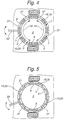
- the means 6 for regulating the inflow cross section 7 'of the scavenging air openings 5' is a rotatable ring 19 'assigned to the first inlet row 11 or the first inflow plane 13 and arranged concentrically to the cylinder 2, with an annular wall 20' in which holes 21 distributed over its circumference 'are arranged.
- Identical components from FIG. 1 are identified by the same reference symbols.
- the swirl of the incoming fresh air can be influenced by a suitable design of the holes 21 ′, such as, for example, a perforated wall of the hole 21 ′ in the ring 19 associated with this purge air opening 5 ′ that is somewhat oblique with respect to the wall of the respective purge air opening 5 ′ '.
- the holes 21 'of the ring 19' are arranged such that they lie congruent to the purge air openings 5 'in a first position of the ring 19' for the complete opening of the inflow cross-section 7 '(see FIG. 4) and for the complete sealing off of the inflow cross-section 7'. in a second position of the ring 19 ', the ring wall 20' can be pushed over the inflow cross section 7 '(corresponds to the illustration in FIG. 5).
- the inflow cross section 7 of the purge air openings 5 ' can be regulated continuously with the ring 19' between the fully open position and the completely locked position, for example with a guide rod 22 'shown schematically in FIG. 4, which is fastened to the ring wall 20' and with which the ring 19 'is rotatable in the directions shown by arrows.
- FIG. 5 shows a section V - V from FIG. 3.
- the means 6 for regulating the inflow cross section 7 of the purge air openings 5 is a second movable ring 19, which is assigned to the second inlet row 12 and the second inflow plane 14 and is arranged concentrically to the cylinder 2 with an annular wall 20 in which holes 21 distributed over the circumference thereof are arranged.
- the rotatable ring 19 is shown in a position in which the purge air openings 5 of the second inlet row 12 are completely closed.
- the ring 19 from FIG. 5 is structurally identical to the ring 19 'from FIG. 4.
- the same components from FIG. 1 are identified by the same reference numerals.
- the means 6 for regulating the inflow cross section 7 are assigned to the scavenging air openings 5 and pivotable about an axis 17 guide vanes 18, these being pivotable in such a way that the inflow cross section 7 of the scavenging air openings 5 is infinitely variable and can be completely shut off except for gap currents .
- 6 and 7 only a cross section through one of the inflow planes 13 and 14 is shown.
- the same components from FIG. 3 are identified by the same reference symbols.
- the guide vanes 18 can be pivoted via an adjusting ring 30, which is known in principle and can be rotated concentrically to the cylinder 2 and is shown in broken lines.
- Each guide vane 18 has a guide pin, not shown, which engages in a receptacle arranged on the circumference of the adjusting ring 30.
- the guide bolts of the guide vanes 18 are taken along and the respective guide vane 18 is rotated about its pivot axis 17.
- the guide vanes for influencing the swirl of the incoming fresh air are fixed or pivotable guide vanes assigned to the scavenging air openings, through the profiling and / or pivoting position of which the swirl of the incoming fresh air can be influenced particularly effectively.
- the guide vanes 18 described in FIGS. 6 and 7 (primarily influencing the swirl of the fresh air supplied) are provided in the inlet row 12, whereas the ring 19 ′ described in FIG. 4 is located in the lower inlet row 11. (primarily influencing the volume flow of the fresh air supplied).
- FIG. 8 shows part of a development of the two inlet rows 11, 12 from FIG. 1, a position UT of the piston top edge at the bottom dead center of the piston 3 being indicated.
- the purge air openings 5, 5 'of each inlet row 11, 12 are bores 11a, 12a arranged uniformly on the circumference of the cylinder 2, the bores 11a of the lower inlet row 11 being radial and the bores 12a of the upper inlet row 12 being tangential to the cylinder 2.
- the purge air openings of the inlet rows have a different inlet geometry such that the inflow into the cylinder takes place tangentially in the lower inlet row and radially in the upper inlet row, or that both inlet rows have approximately the same inlet geometry exhibit.
- the invention is shown in the exemplary embodiments shown with two inflow levels.
- the means for influencing the swirl and / or for controlling the volume flow of the fresh air can also be provided in intake systems with only one inflow level and / or only one inflow unit.
- the invention can of course be used for two-stroke internal combustion engines with and without a separate purge air pump.
Landscapes
- Engineering & Computer Science (AREA)
- Chemical & Material Sciences (AREA)
- Combustion & Propulsion (AREA)
- Mechanical Engineering (AREA)
- General Engineering & Computer Science (AREA)
- Supplying Secondary Fuel Or The Like To Fuel, Air Or Fuel-Air Mixtures (AREA)
- Cylinder Crankcases Of Internal Combustion Engines (AREA)
Applications Claiming Priority (2)
| Application Number | Priority Date | Filing Date | Title |
|---|---|---|---|
| DE19507220 | 1995-03-02 | ||
| DE19507220A DE19507220A1 (de) | 1995-03-02 | 1995-03-02 | Einlaßsystem für eine Zweitakt-Brennkraftmaschine |
Publications (3)
| Publication Number | Publication Date |
|---|---|
| EP0731264A2 true EP0731264A2 (fr) | 1996-09-11 |
| EP0731264A3 EP0731264A3 (fr) | 1997-04-23 |
| EP0731264B1 EP0731264B1 (fr) | 1999-05-26 |
Family
ID=7755410
Family Applications (1)
| Application Number | Title | Priority Date | Filing Date |
|---|---|---|---|
| EP96101418A Expired - Lifetime EP0731264B1 (fr) | 1995-03-02 | 1996-02-01 | Système d'admission pour un moteur à combustion interne du type à deux temps |
Country Status (3)
| Country | Link |
|---|---|
| US (1) | US5638780A (fr) |
| EP (1) | EP0731264B1 (fr) |
| DE (2) | DE19507220A1 (fr) |
Families Citing this family (12)
| Publication number | Priority date | Publication date | Assignee | Title |
|---|---|---|---|---|
| US5769040A (en) * | 1997-04-18 | 1998-06-23 | Christner; Oval F. | Two cycle internal combustion engine |
| DE19755689A1 (de) * | 1997-12-16 | 1999-06-24 | Blodig Guenter Priv Doz Dr Ing | Vorrichtung zur Verstellung des Dralls bei Brennkraftmaschinen |
| DE10009793A1 (de) * | 2000-03-01 | 2001-09-06 | Stihl Maschf Andreas | Zweitaktmotor mit einstellbarem Ladungsprinzip |
| US6397795B2 (en) | 2000-06-23 | 2002-06-04 | Nicholas S. Hare | Engine with dry sump lubrication, separated scavenging and charging air flows and variable exhaust port timing |
| US6644263B2 (en) | 2001-12-04 | 2003-11-11 | Nicholas S. Hare | Engine with dry sump lubrication |
| US7004120B2 (en) * | 2003-05-09 | 2006-02-28 | Warren James C | Opposed piston engine |
| DE102010038192A1 (de) * | 2010-10-14 | 2012-04-19 | Dr. Ing. H.C. F. Porsche Aktiengesellschaft | Zweitaktmotor |
| JP2012219727A (ja) * | 2011-04-11 | 2012-11-12 | Diesel United:Kk | 予混合式2ストローク機関 |
| GB2490397A (en) * | 2011-04-25 | 2012-10-31 | Ecomotors Internat Inc | Cylinder having a first plurality of intake ports and a second plurality of intake ports at respective first and second distances from a crankshaft |
| EP3037639A3 (fr) * | 2014-12-22 | 2016-07-13 | Winterthur Gas & Diesel AG | Système de cylindre pour un moteur à combustion à piston élévateur rincé en longueur, ainsi qu'élément d'étranglement pour un revêtement de cylindre |
| CN105402057A (zh) * | 2015-12-08 | 2016-03-16 | 安徽中鼎动力有限公司 | 一种二冲程水平对置活塞、对置气缸发动机的进气道 |
| US11415075B2 (en) | 2019-07-08 | 2022-08-16 | Cummins Inc. | Port shapes for enhanced engine breathing |
Family Cites Families (24)
| Publication number | Priority date | Publication date | Assignee | Title |
|---|---|---|---|---|
| GB273143A (en) * | 1926-11-01 | 1927-06-30 | Sun Shipbuilding & Dry Dock Co | Improvements in scavenging ports for the cylinders of internal combustion engines |
| DE488428C (de) * | 1927-06-11 | 1929-12-28 | Paul Schauer | Brennkraftmaschine |
| US1992328A (en) * | 1930-09-25 | 1935-02-26 | Sulzer Ag | Double-acting two-stroke internal combustion engine |
| CH163982A (de) * | 1932-06-29 | 1933-09-15 | Sulzer Ag | Verfahren zum Betrieb von Zweitaktbrennkraftmaschinen. |
| US2038271A (en) * | 1933-03-03 | 1936-04-21 | Curtis Gas Engine Corp | Two-cycle internal combustion engine |
| US2137344A (en) * | 1936-04-08 | 1938-11-22 | John J Mccarthy | Directional intake control for internal combustion engines |
| DE695502C (de) * | 1937-10-23 | 1940-08-26 | Maschf Augsburg Nuernberg Ag | Zweitaktbrennkraftmaschine mit Gleichstromspuelung |
| US2236742A (en) * | 1939-10-02 | 1941-04-01 | Newell O Allyn | Diesel engine |
| US2409761A (en) * | 1945-02-24 | 1946-10-22 | Gen Motors Corp | Sleeve valve engine |
| CH245172A (de) * | 1945-07-07 | 1946-10-31 | Saurer Ag Adolph | Zweitakt-Brennkraftmaschine mit zentraler Spülströmung. |
| US2523599A (en) * | 1945-11-27 | 1950-09-26 | Sparmann Edmund Ernst Karl | Two-cycle engine sleeve valve control of scavenging |
| FR1023618A (fr) * | 1950-08-19 | 1953-03-20 | Snecma | Perfectionnement aux moteurs à deux temps |
| DE970977C (de) * | 1950-12-05 | 1958-11-20 | Kreidler Dipl Ing Alfred | Schnell laufende Zweitaktbrennkraftmaschine |
| DE1015267B (de) * | 1954-01-21 | 1957-09-05 | Eugen Wilhelm Huber Dr Ing | Mit innerer Gemischbildung arbeitende Zweitaktbrennkraftmaschine mit Gleichstromspuelung |
| US3000366A (en) * | 1958-07-28 | 1961-09-19 | Walter L Blackburn | Opposed piston engine |
| JPS5510021A (en) * | 1978-07-05 | 1980-01-24 | Toyota Motor Corp | 2-cycle gasoline engine |
| JPS5523313A (en) * | 1978-08-02 | 1980-02-19 | Toyota Motor Corp | Two-cycle diesel engine |
| JPS5825845B2 (ja) * | 1978-09-18 | 1983-05-30 | トヨタ自動車株式会社 | 二サイクルガソリンエンジン |
| DE2932627A1 (de) * | 1979-08-11 | 1981-02-26 | Maschf Augsburg Nuernberg Ag | Zwei-takt-verbrennungsmotor mit gleichstromgespuelten zylindern |
| DE3510770A1 (de) * | 1985-03-25 | 1986-10-16 | Gebrüder Sulzer AG, Winterthur | Zweitakt-brennkraftmaschine mit im zylinderkopf angeordnetem auslassventil |
| JPS61258924A (ja) * | 1985-05-11 | 1986-11-17 | Mitsubishi Heavy Ind Ltd | シリンダライナの可変スワ−ル型掃気ポ−ト |
| AT384079B (de) * | 1985-06-07 | 1987-09-25 | Avl Verbrennungskraft Messtech | Zweitakt-brennkraftmaschine mit gleichstromspuelung |
| DE4133138A1 (de) * | 1991-10-07 | 1992-02-27 | Bernd Fischer | Verfahren zur geregelten beeinflussung der beschaffenheit der zylinderladung von zweitaktdieselmotoren, insbesondere solcher mit partikelfilter oder katalysator |
| JPH05280344A (ja) * | 1992-04-02 | 1993-10-26 | Toyota Motor Corp | 2サイクル内燃機関 |
-
1995
- 1995-03-02 DE DE19507220A patent/DE19507220A1/de not_active Withdrawn
-
1996
- 1996-02-01 EP EP96101418A patent/EP0731264B1/fr not_active Expired - Lifetime
- 1996-02-01 DE DE59601966T patent/DE59601966D1/de not_active Expired - Fee Related
- 1996-03-01 US US08/609,245 patent/US5638780A/en not_active Expired - Fee Related
Also Published As
| Publication number | Publication date |
|---|---|
| EP0731264A3 (fr) | 1997-04-23 |
| DE59601966D1 (de) | 1999-07-01 |
| US5638780A (en) | 1997-06-17 |
| EP0731264B1 (fr) | 1999-05-26 |
| DE19507220A1 (de) | 1996-09-05 |
Similar Documents
| Publication | Publication Date | Title |
|---|---|---|
| EP0685028B1 (fr) | Moteur a piston a allumage par bougies, dont le sens d'admission du melange carburant-air peut etre modifie | |
| DE69103000T2 (de) | Luftansauganlage für eine brennkraftmaschine. | |
| DE3624899C2 (fr) | ||
| DE69012150T2 (de) | Wellenprallplatte aus einem stück für das einlasssystem einer brennkraftmaschine. | |
| EP0214251B1 (fr) | Dispositif de chargement a turbulence et/ou a cyclone pour moteurs a combustion | |
| AT402535B (de) | Brennkraftmaschine mit zumindest zwei einlassventilen je motorzylinder | |
| DE102010016284A1 (de) | Luftansaugvorrichtung für einen Verbrennungsmotor | |
| AT402326B (de) | Zylinderkopf für eine brennkraftmaschine | |
| EP0731264B1 (fr) | Système d'admission pour un moteur à combustion interne du type à deux temps | |
| EP0771941B1 (fr) | Culasse pour moteur à combustion interne | |
| DE3138615A1 (de) | "stroemungsveraenderungsvorrichtung, insbesondere drallkoerper" | |
| DE2657890A1 (de) | Brennkraftmaschine mit einem von kuehlwasser durchstroemten zylinderblock | |
| EP0676533B1 (fr) | Système de cannaux d'admission pour un moteur à combustion interne | |
| EP0204687B1 (fr) | Moteur à combustion interne à deux temps | |
| DE69415356T2 (de) | Auszugsystem für eine Brennkraftmaschine | |
| AT402433B (de) | Zylinderkopf für eine brennkraftmaschine | |
| DE10338132B4 (de) | Einlasskanalanordnung für eine Brennkraftmaschine | |
| DE29507321U1 (de) | Kolbenbrennkraftmaschine mit zumindest zwei Einlaßventilen je Zylinder | |
| DE69407693T2 (de) | Brennkraftmaschine | |
| DE2731687C3 (de) | Ottomotor mit einer Verbrennungskammer mit Zündkerze sowie mit einer Vorkammer | |
| DE69221651T2 (de) | Einlasssystem für eine Brennkraftmaschine | |
| DE19743419A1 (de) | Einlaßanordnung eines Verbrennungsmotors | |
| DE3614145A1 (de) | Vergaser | |
| DE10042247C5 (de) | Mischeinheit für Gasströme an einer Verbrennungskraftmaschine | |
| DE4405664C1 (de) | Vorrichtung zum Zuführen von Gemisch beziehungsweise Luft zu einem Zylinder eines Verbrennungsmotors |
Legal Events
| Date | Code | Title | Description |
|---|---|---|---|
| PUAI | Public reference made under article 153(3) epc to a published international application that has entered the european phase |
Free format text: ORIGINAL CODE: 0009012 |
|
| AK | Designated contracting states |
Kind code of ref document: A2 Designated state(s): DE FR GB IT |
|
| PUAL | Search report despatched |
Free format text: ORIGINAL CODE: 0009013 |
|
| AK | Designated contracting states |
Kind code of ref document: A3 Designated state(s): DE FR GB IT |
|
| 17P | Request for examination filed |
Effective date: 19970319 |
|
| 17Q | First examination report despatched |
Effective date: 19970613 |
|
| GRAG | Despatch of communication of intention to grant |
Free format text: ORIGINAL CODE: EPIDOS AGRA |
|
| GRAG | Despatch of communication of intention to grant |
Free format text: ORIGINAL CODE: EPIDOS AGRA |
|
| GRAH | Despatch of communication of intention to grant a patent |
Free format text: ORIGINAL CODE: EPIDOS IGRA |
|
| GRAH | Despatch of communication of intention to grant a patent |
Free format text: ORIGINAL CODE: EPIDOS IGRA |
|
| RAP1 | Party data changed (applicant data changed or rights of an application transferred) |
Owner name: DAIMLERCHRYSLER AG |
|
| GRAA | (expected) grant |
Free format text: ORIGINAL CODE: 0009210 |
|
| AK | Designated contracting states |
Kind code of ref document: B1 Designated state(s): DE FR GB IT |
|
| REF | Corresponds to: |
Ref document number: 59601966 Country of ref document: DE Date of ref document: 19990701 |
|
| GBT | Gb: translation of ep patent filed (gb section 77(6)(a)/1977) |
Effective date: 19990610 |
|
| ET | Fr: translation filed | ||
| PGFP | Annual fee paid to national office [announced via postgrant information from national office to epo] |
Ref country code: GB Payment date: 20000124 Year of fee payment: 5 |
|
| PGFP | Annual fee paid to national office [announced via postgrant information from national office to epo] |
Ref country code: FR Payment date: 20000222 Year of fee payment: 5 |
|
| PLBE | No opposition filed within time limit |
Free format text: ORIGINAL CODE: 0009261 |
|
| STAA | Information on the status of an ep patent application or granted ep patent |
Free format text: STATUS: NO OPPOSITION FILED WITHIN TIME LIMIT |
|
| PGFP | Annual fee paid to national office [announced via postgrant information from national office to epo] |
Ref country code: DE Payment date: 20000420 Year of fee payment: 5 |
|
| 26N | No opposition filed | ||
| PG25 | Lapsed in a contracting state [announced via postgrant information from national office to epo] |
Ref country code: GB Free format text: LAPSE BECAUSE OF NON-PAYMENT OF DUE FEES Effective date: 20010201 |
|
| GBPC | Gb: european patent ceased through non-payment of renewal fee |
Effective date: 20010201 |
|
| PG25 | Lapsed in a contracting state [announced via postgrant information from national office to epo] |
Ref country code: FR Free format text: LAPSE BECAUSE OF NON-PAYMENT OF DUE FEES Effective date: 20011031 |
|
| REG | Reference to a national code |
Ref country code: FR Ref legal event code: ST |
|
| PG25 | Lapsed in a contracting state [announced via postgrant information from national office to epo] |
Ref country code: DE Free format text: LAPSE BECAUSE OF NON-PAYMENT OF DUE FEES Effective date: 20011201 |
|
| PG25 | Lapsed in a contracting state [announced via postgrant information from national office to epo] |
Ref country code: IT Free format text: LAPSE BECAUSE OF NON-PAYMENT OF DUE FEES;WARNING: LAPSES OF ITALIAN PATENTS WITH EFFECTIVE DATE BEFORE 2007 MAY HAVE OCCURRED AT ANY TIME BEFORE 2007. THE CORRECT EFFECTIVE DATE MAY BE DIFFERENT FROM THE ONE RECORDED. Effective date: 20050201 |