EP0731273A2 - Kolben mit Kolbenstange - Google Patents
Kolben mit Kolbenstange Download PDFInfo
- Publication number
- EP0731273A2 EP0731273A2 EP96810106A EP96810106A EP0731273A2 EP 0731273 A2 EP0731273 A2 EP 0731273A2 EP 96810106 A EP96810106 A EP 96810106A EP 96810106 A EP96810106 A EP 96810106A EP 0731273 A2 EP0731273 A2 EP 0731273A2
- Authority
- EP
- European Patent Office
- Prior art keywords
- piston
- rod
- rod head
- swash plate
- spherical
- Prior art date
- Legal status (The legal status is an assumption and is not a legal conclusion. Google has not performed a legal analysis and makes no representation as to the accuracy of the status listed.)
- Granted
Links
Images


Classifications
-
- F—MECHANICAL ENGINEERING; LIGHTING; HEATING; WEAPONS; BLASTING
- F04—POSITIVE - DISPLACEMENT MACHINES FOR LIQUIDS; PUMPS FOR LIQUIDS OR ELASTIC FLUIDS
- F04B—POSITIVE-DISPLACEMENT MACHINES FOR LIQUIDS; PUMPS
- F04B53/00—Component parts, details or accessories not provided for in, or of interest apart from, groups F04B1/00 - F04B23/00 or F04B39/00 - F04B47/00
- F04B53/14—Pistons, piston-rods or piston-rod connections
- F04B53/144—Adaptation of piston-rods
- F04B53/147—Mounting or detaching of piston rod
-
- B—PERFORMING OPERATIONS; TRANSPORTING
- B21—MECHANICAL METAL-WORKING WITHOUT ESSENTIALLY REMOVING MATERIAL; PUNCHING METAL
- B21K—MAKING FORGED OR PRESSED METAL PRODUCTS, e.g. HORSE-SHOES, RIVETS, BOLTS OR WHEELS
- B21K25/00—Uniting components to form integral members, e.g. turbine wheels and shafts, caulks with inserts, with or without shaping of the components
-
- B—PERFORMING OPERATIONS; TRANSPORTING
- B23—MACHINE TOOLS; METAL-WORKING NOT OTHERWISE PROVIDED FOR
- B23P—METAL-WORKING NOT OTHERWISE PROVIDED FOR; COMBINED OPERATIONS; UNIVERSAL MACHINE TOOLS
- B23P11/00—Connecting or disconnecting metal parts or objects by metal-working techniques not otherwise provided for
- B23P11/005—Connecting or disconnecting metal parts or objects by metal-working techniques not otherwise provided for by expanding or crimping
-
- F—MECHANICAL ENGINEERING; LIGHTING; HEATING; WEAPONS; BLASTING
- F04—POSITIVE - DISPLACEMENT MACHINES FOR LIQUIDS; PUMPS FOR LIQUIDS OR ELASTIC FLUIDS
- F04B—POSITIVE-DISPLACEMENT MACHINES FOR LIQUIDS; PUMPS
- F04B27/00—Multi-cylinder pumps specially adapted for elastic fluids and characterised by number or arrangement of cylinders
- F04B27/08—Multi-cylinder pumps specially adapted for elastic fluids and characterised by number or arrangement of cylinders having cylinders coaxial with, or parallel or inclined to, main shaft axis
- F04B27/0873—Component parts, e.g. sealings; Manufacturing or assembly thereof
- F04B27/0878—Pistons
-
- F—MECHANICAL ENGINEERING; LIGHTING; HEATING; WEAPONS; BLASTING
- F04—POSITIVE - DISPLACEMENT MACHINES FOR LIQUIDS; PUMPS FOR LIQUIDS OR ELASTIC FLUIDS
- F04B—POSITIVE-DISPLACEMENT MACHINES FOR LIQUIDS; PUMPS
- F04B39/00—Component parts, details, or accessories, of pumps or pumping systems specially adapted for elastic fluids, not otherwise provided for in, or of interest apart from, groups F04B25/00 - F04B37/00
- F04B39/0005—Component parts, details, or accessories, of pumps or pumping systems specially adapted for elastic fluids, not otherwise provided for in, or of interest apart from, groups F04B25/00 - F04B37/00 adaptations of pistons
- F04B39/0022—Component parts, details, or accessories, of pumps or pumping systems specially adapted for elastic fluids, not otherwise provided for in, or of interest apart from, groups F04B25/00 - F04B37/00 adaptations of pistons piston rods
-
- F—MECHANICAL ENGINEERING; LIGHTING; HEATING; WEAPONS; BLASTING
- F16—ENGINEERING ELEMENTS AND UNITS; GENERAL MEASURES FOR PRODUCING AND MAINTAINING EFFECTIVE FUNCTIONING OF MACHINES OR INSTALLATIONS; THERMAL INSULATION IN GENERAL
- F16J—PISTONS; CYLINDERS; SEALINGS
- F16J1/00—Pistons; Trunk pistons; Plungers
- F16J1/10—Connection to driving members
- F16J1/14—Connection to driving members with connecting-rods, i.e. pivotal connections
- F16J1/22—Connection to driving members with connecting-rods, i.e. pivotal connections with universal joint, e.g. ball-joint
-
- B—PERFORMING OPERATIONS; TRANSPORTING
- B21—MECHANICAL METAL-WORKING WITHOUT ESSENTIALLY REMOVING MATERIAL; PUNCHING METAL
- B21H—MAKING PARTICULAR METAL OBJECTS BY ROLLING, e.g. SCREWS, WHEELS, RINGS, BARRELS, BALLS
- B21H7/00—Making articles not provided for in the preceding groups, e.g. agricultural tools, dinner forks, knives, spoons
- B21H7/18—Making articles not provided for in the preceding groups, e.g. agricultural tools, dinner forks, knives, spoons grooved pins; Rolling grooves, e.g. oil grooves, in articles
- B21H7/182—Rolling annular grooves
-
- Y—GENERAL TAGGING OF NEW TECHNOLOGICAL DEVELOPMENTS; GENERAL TAGGING OF CROSS-SECTIONAL TECHNOLOGIES SPANNING OVER SEVERAL SECTIONS OF THE IPC; TECHNICAL SUBJECTS COVERED BY FORMER USPC CROSS-REFERENCE ART COLLECTIONS [XRACs] AND DIGESTS
- Y10—TECHNICAL SUBJECTS COVERED BY FORMER USPC
- Y10T—TECHNICAL SUBJECTS COVERED BY FORMER US CLASSIFICATION
- Y10T29/00—Metal working
- Y10T29/49—Method of mechanical manufacture
- Y10T29/49229—Prime mover or fluid pump making
- Y10T29/49249—Piston making
- Y10T29/49252—Multi-element piston making
-
- Y—GENERAL TAGGING OF NEW TECHNOLOGICAL DEVELOPMENTS; GENERAL TAGGING OF CROSS-SECTIONAL TECHNOLOGIES SPANNING OVER SEVERAL SECTIONS OF THE IPC; TECHNICAL SUBJECTS COVERED BY FORMER USPC CROSS-REFERENCE ART COLLECTIONS [XRACs] AND DIGESTS
- Y10—TECHNICAL SUBJECTS COVERED BY FORMER USPC
- Y10T—TECHNICAL SUBJECTS COVERED BY FORMER US CLASSIFICATION
- Y10T29/00—Metal working
- Y10T29/49—Method of mechanical manufacture
- Y10T29/49229—Prime mover or fluid pump making
- Y10T29/49249—Piston making
- Y10T29/49268—Piston making with other attaching provision for connecting rod
Definitions
- the invention relates to a piston with a piston rod for high pressures, in particular a swash plate compressor, which has a plurality of pistons arranged next to one another in its circumferential direction, which are connected to rods, the two ends of which are pivotally supported by spherical rod heads on the one hand on the piston and on the other hand on the swash plate in ball receptacles ,
- a piston of a hydraulic swash plate device in which an essentially spherical rod head has a beveled section, which enables a fitting into a correspondingly shaped ball receptacle when the rod is in a position outside its normal swivel range.
- the invention has for its object to find a piston of the type mentioned, which can absorb particularly high forces and which is easy to manufacture.
- a piston of the type mentioned at the outset is proposed, which is characterized in accordance with the invention in that the piston has an uninterrupted circumferential indentation between the front and rear piston regions, which forms an undercut enclosing the spherical rod head on the inside.
- the ball receptacle is hemispherical and is delimited in the direction of the rear piston area by a soft-elastic sealing ring sealingly sealing the spherical rod head, so that the rod head is held in the ball receptacle by the gas pressure acting on the rear area of the piston is.
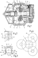
- Pistons 1 with a ball joint-like connection between piston rod 2 and piston 1 are e.g. due to the type of rod movement required for swash plate compressors. 1 shows an embodiment of such an application.
- the basic structure and the basic mode of operation are known from the specialist literature, e.g. by US-A-5,205,718.
- the swash plate 6 is held by a radial bearing 7 and an axial bearing 8 on a disc carrier 10 rotating and pivotably mounted with the drive shaft 9, so that the rotary movement of the inclined disc carrier 10 causes a wobble movement of the swash plate 6 and consequently the pistons 1 connected to the latter Carry out lifting movement.
- the connection between the drive shaft 9 and the disk carrier 10 takes place by means of a driver joint 12 provided at the end of a driver arm 11.
- the piston shape and the size of the spherical rod heads 4.5 are to be adjusted due to the high forces acting on the piston 1 so that the size of the diameter of the rod head 4 approaches considerably, for example up to more than 70%, the diameter of the piston 1.
- the invention is concerned, inter alia, with adapting the piston 1 or the connection between the latter and the piston rod 2 to such extreme conditions, with little manufacturing effort, that it is particularly reliable and durable, inter alia, due to low surface pressures on the ball receptacles 14.
- the rod head 4 has a diameter of approximately 70% of the largest piston diameter.
- the diameter of the rod head is even more than 80%, so that the remaining thickness of the side piston wall 15, including the rod head 4, with respect to the Strength requirements are reduced to a minimum.
- the piston 1 At its front area 16 and its rear area, the piston 1 has a larger diameter, on the one hand to provide a groove 18 for receiving a piston ring (not shown) and on the other hand a guide surface at the rear end of the piston.
- a circumferential indentation 21 is provided by material deformation, starting from a cylindrical wall, so that it surrounds the spherical rod head 4 in such a way that it is positively and securely held in the ball seat 14 of the piston 1.
- FIG. 4 shows schematically an example of the arrangement of rotatably mounted, disk-shaped deformation tools 22 on the circumference of the piston 1 during the production of the circumferential indentation 21, which is intended to establish the permanent connection between the piston 1 and the piston rod 2.
- the deformation tools 22 are rounded on their circumference in order to produce the circumferential indentation 21, which is rounded in cross section, in its rotation relative to the piston 1 and radial pressure against the piston wall 15.
- the piston wall 15 can also be deformed by the pressure of a hydraulic medium to conform to the shape of the spherical rod head.
- 5 and 6 show a mold 24 suitable for this purpose.
- a plurality of cylindrical receiving spaces 25 are provided for each piston 1, into which, starting from a central channel 26, a plurality of branch lines 27 open in an area on which the wall region 15 of the piston 1 is arranged.
- the number of e.g. seven and the arrangement of the receiving spaces 25 in the mold 24 corresponds to that of the cylinder spaces of a swash plate machine 3, so that the mold 24 is also an assembly tool.
- the cylindrical inner wall of the receiving spaces 25 is adapted at least at its edge region with a small tolerance to the outer diameter of the piston 1 in its rear region, so that a correspondingly small sealing gap there enables sufficient hydraulic pressure to bulge the previously cylindrical piston wall 15 inwards, so that the spherical rod head 4 is positively enclosed in the piston 1. Regulation of the hydraulic pressure prevents the Rod head 4 is clamped in the cavity of the piston 1. To secure the piston rod units 1, 2 during the hydraulic deformation in the molding tool 24, this is covered by a closing plate 29.
- This can be rotated back and forth between two positions by guiding at four arc-shaped elongated holes 30 and screw bolts 31 arranged in them, in order to arrange the openings 32 above the receiving spaces 25 when the piston rod units 1, 2 are inserted into the molding tool 24 and around them to move into the closed position shown in Figure 6, in which only the piston rod 2 can extend through a slot 33 adjoining the opening 32 to the outside.
- the spherical rod head 4 can also be held by a sealing ring 35 inserted on the inside of this piston wall 15.
- This sealing ring 35 has a U-shaped cross-section which rests on the rod head 4 and is directed toward the piston rod 2 towards the flexible sealing lip 36 and is arranged adjacent to the hemispherical inner surface 37 of the ball receptacle 14.
- the sealing lip 36 lies against the area 38 of the rod head 4 which tapers from the largest ball diameter to the piston rod 2.
- the sealing ring 35 is shaped such that the inner surface 37 of the ball receptacle 14 adjoins the sealing ring 35 essentially without gaps.
Landscapes
- Engineering & Computer Science (AREA)
- Mechanical Engineering (AREA)
- General Engineering & Computer Science (AREA)
- Chemical & Material Sciences (AREA)
- Combustion & Propulsion (AREA)
- Manufacturing & Machinery (AREA)
- Compressors, Vaccum Pumps And Other Relevant Systems (AREA)
- Compressor (AREA)
- Pistons, Piston Rings, And Cylinders (AREA)
Abstract
Description
- Die Erfindung betrifft einen Kolben mit Kolbenstange für hohe Drücke, insbesondere eines Taumelscheibenverdichters, der mehrere in seiner Umfangsrichtung nebeneinander angeordnete Kolben aufweist, die mit Stangen verbunden sind, deren beiden Enden durch kugelförmige Stangenköpfe schwenkbar einerseits am Kolben und andererseits an der Taumelscheibe in Kugelaufnahmen gelagert sind,
- Durch die DE-A-4024319 ist ein Kolben einer hydraulischen Taumelscheibeneinrichtung bekannt, bei dem ein im wesentlichen kugelförmiger Stangenkopf einen abgeschrägten Teilabschnitt aufweist, der ein Einpassen in eine entsprechend geformte Kugelaufnahme ermöglicht, wenn sich die Stange in einer Stellung ausserhalb ihres normalen Schwenkbereichs befindet.
- Weiterhin ist es bekannt, den kugelförmigen Stangenkopf formschlüssig in einer Kugelaufnahme eines Kolbens zu halten, indem aus einem sich an die halbkugelförmige Kugelaufnahme anschliessenden, umlaufenden Wandteil einzelne Lappen u-förmig herausgeschnitten und nach innen gebogen werden, so dass sie den Stangenkopf hinterfassen. Eine solcher Kolben ist jedoch für verhältnismässig hohe Drücke nicht geeignet, da dann der Durchmesser des Stangenkopfes nur wenig kleiner sein kann als der Kolbendurchmesser.
- Der Erfindung liegt die Aufgabe zugrunde, einen Kolben der genannten Art zu finden, der besonders hohe Kräfte aufnehmen kann und der dabei einfach herstellbar ist.
- Zur Lösung dieser Aufgabe wird ein Kolben der eingangs genannten Art vorgeschlagen, das erfindungsgemäss dadurch gekennzeichnet ist, dass der Kolben zwischen dem vorderen und hinteren Kolbenbereich eine unterbrechungsfrei umlaufende Einbuchtung aufweist, die nach innen eine den kugelförmigen Stangenkopf einschliessende Hinterschneidung bildet.
- Eine weitere Lösung dieser Aufgabe erfolgt erfindungsgemäss dadurch, dass die Kugelaufnahme halbkugelförmig ist und in Richtung zum hinteren Kolbenbereich durch einen den kugelförmigen Stangenkopf dichtend umschliessenden, weichelastischen Dichtring begrenzt ist, so dass der Stangenkopf durch den am hinteren Bereich des Kolbens wirkenden Gasdruck in der Kugelaufnahme gehalten ist.
- Weiterhin wird ein Verfahren sowie eine Form zur Herstellung des mit einer Einbuchtung versehenen Kolbens vorgeschlagen.
- Vorteilhafte Ausführungsformen der Erfindung sind Gegenstand der abhängigen Patentansprüche und der folgenden Beschreibung anhand der Zeichnungen zu entnehmen.
- Es zeigt:
- Fig.1
- einen Querschnitt durch einen Taumelscheibenverdichter,
- Fig.2
- eine Seitenansicht eines erfindungsgemässen Kolbens,
- Fig.3
- einen Querschnitt durch den Kolben nach Fig.2,
- Fig.4
- eine Aufsicht auf den Kolben nach Fig.2 mit drei sich in Verformungseingriff befindlichen Rollwerkzeugen,
- Fig.5
- eine Querschnitt einer Form für die hydraulische Formgebung eines erfindungsgemässen Kolbens,
- Fig.6
- eine Aufsicht auf die Form nach Fig.5 und
- Fig.7
- einen Querschnitt durch einen Kolben mit einer Dichtung am Umfang des Stangenkopfes.
- Kolben 1 mit einer kugelgelenkartigen Verbindung zwischen Kolbenstange 2 und Kolben 1 werden aufgrund der Art der Stangenbewegung z.B. für Taumelscheibenverdichter benötigt. Fig.1 zeigt ein Ausführungsbeispiel einer solchen Anwendung. Der grundsätzliche Aufbau und die grundsätzliche Wirkungsweise sind durch die Fachliteratur bekannt, wie z.B. durch die US-A-5,205,718.
- Die Kolben 1 des Taumelscheibenverdichters 3, von denen beispielsweise sieben in Umfangsrichtung des Verdichters nebeneinander angeordnet sind, werden durch Stangen 2 betätigt, deren beiden Enden durch Kugelköpfe 4,5 schwenkbar einerseits am Kolben 1 und andererseits an der Taumelscheibe 6 in Kugelaufnahmen 14 gelagert sind.
- Die Taumelscheibe 6 ist durch ein Radiallager 7 und ein Axiallager 8 auf einem sich mit der Antriebswelle 9 drehenden und schwenkbar gelagerten Scheibenträger 10 gehalten, so dass die Drehbewegung des schräggestellten Scheibenträgers 10 eine Taumelbewegung der Taumelscheibe 6 bewirkt und folglich die mit letzerer verbundenen Kolben 1 eine Hubbewegung ausführen. Die Verbindung zwischen der Antriebswelle 9 und dem Scheibenträger 10 erfolgt durch ein am Ende eines Mitnehmerarmes 11 vorgesehenes Mitnehmergelenk 12.
- Die Schwenkbewegung des Scheibenträgers 10 und der auf diesem gelagerten Taumelscheibe 6 um das Mitnehmergelenk 12 ergibt sich durch die Differenz der beidseitig der Kolben 1 wirkenden Drücke. Entsprechend der Neigung der Taumelscheibe ändert sich der untere Totpunkt der Kolbenbewegung während der obere Totpunkt unverändert bleibt. Je höher der Druck an der Unterseite der Kolben 1 bzw. im Triebraum 13 relativ zum Druck auf der Oberseite der Kolben 1 bzw. auf der Saugseite des Verdichters 3, umso kleiner wird die Hubweite der Kolben 1 und damit die Förderleistung des Verdichters 3. Da zur Aenderung der Neigung der Taumelscheibe Druckgas in den Triebraum geleitet wird, können dort, je nach Anwendung, hohe Drücke auftreten.
- Für die Verdichtung auf hohe Drücke, die für einen überkritisch arbeitenden CO2-Kaltdampfprozess beispielsweise 120 bar betragen, ist die Kolbenform und die Grösse der kugelförmigen Stangenköpfe 4,5 aiufgrund der hohen, am Kolben 1 wirkenden Kräfte so anzupassen, dass die Grösse des Durchmessers des Stangenkopfes 4 sich erheblich, z.B. bis auf mehr als 70 % dem Durchmesser des Kolbens 1 annähert. Die Erfindung befasst sich u.a. damit, den Kolben 1 bzw. die Verbindung zwischen diesem und der Kolbenstange 2 bei geringem Fertigungsaufwand solchen extremen Bedingungen derart anzupassen, dass sie u.a. auch durch geringe Flächenpressungen an den Kugelaufnahmen 14 besonders zuverlässig und dauerhaft ist.
- Beim Ausführungsbeispiel eines erfindungsgemässen Kolbens nach Fig.2 und 3 hat der Stangenkopf 4 einen Durchmesser von ca. 70% des grössten Kolbendurchmessers. Jedoch im Verhältnis zum Kolbendurchmesser im Bereich der Anordnung des Stangenkopfes 4, dort wo der Kolben 1 nach innen abgesetzt ist, beträgt der Durchmesser des Stangenkopfes sogar mehr als 80 %, so dass die verbleibende, den Stangenkopf 4 einschliessende Dicke der seitlichen Kolbenwand 15 hinsichtlich der Festigkeitsanforderungen auf ein Minimum reduziert ist.
- An seinem vorderen Bereich 16 und seinem hinteren Bereich hat der Kolben 1 eine grösseren Durchmesser, um einerseits eine Nut 18 für die Aufnahme eines nichtdargestellten Kolbenringes und andererseits eine Führungsfläche am hinteren Kolbenende vorzusehen.
- Im nach innen abgesetzten mittleren Bereich 20 des Kolbens 1 ist durch Materialverformung, ausgehend von einer zylindrischen Wand, eine umlaufende Einbuchtung 21 vorgesehen, so dass sie den kugelförmigen Stangenkopf 4 so unterfasst, dass er formschlüssig sicher in der Kugelaufnahme 14 des Kolbens 1 gehalten ist.
- Fig.4 zeigt schematisch ein Beispiel für die Anordnung von drehbar gelagerten, scheibenförmigen Verformungswerkzeugen 22 am Umfang des Kolbens 1 während der Herstellung der umlaufenden Einbuchtung 21, die die unlösbare Verbindung zwischen dem Kolben 1 und der Kolbenstange 2 herstellen soll. An ihrem Umfang sind die Verformungswerkzeuge 22 abgerundet, um bei ihrem Umlauf relativ zum Kolben 1 und radialem Druck gegen die Kolbenwand 15 die im Querschnitt gerundete, umlaufende Einbuchtung 21 herzustellen.
- Anstatt durch mechanische Materialverformung mittels der Rollwerkzeuge 22 kann eine sich an die Form des kugelförmigen Stangenkopfes anschmiegende Verformung der Kolbenwand 15 auch durch den Druck eines Hydraulikmediums erfolgen. Fig.5 und 6 zeigen ein hierfür geeignetes Formwerkzeug 24. In diesem Formwerkzeug sind mehrere zylindrische Aufnahmeräume 25 für je einen Kolben 1 vorgesehen, in die ausgehend von einem Zentralkanal 26 mehrere Zweigleitungen 27 in einem Bereich münden, an dem der Wandbereich 15 des Kolbens 1 angeordnet ist. Die Anzahl von z.B. sieben und die Anordnung der Aufnahmeräume 25 im Formwerkzeug 24 entspricht derjenigen der Zylinderräume einer Taumelscheibenmaschine 3, so dass das Formwerkzeug 24 gleichzeitig ein Montagewerkzeug ist.
- Die zylindrische Innenwand der Aufnahmeräume 25 ist zumindest an ihrem Randbereich mit kleiner Toleranz an den Aussendurchmesser des Kolbens 1 in dessen hinteren Bereich angepasst, so dass dort ein entsprechend kleiner Dichtspalt einen ausreichenden Hydraulikdruck ermöglicht, um die zuvor zylindrische Kolbenwand 15 nach innen auszuwölben, so dass der kugelförmige Stangenkopf 4 formschlüssig im Kolben 1 eingeschlossen wird. Eine Regelung des Hydraulidruckes verhindert, dass der Stangenkopf 4 im Hohlraum des Kolbens 1 festgeklemmt wird. Für die Sicherung der Kolben-Stangeneinheiten 1,2 während der hydraulischen Verformung im Formwerkzeug, 24 ist dieses durch eine Verschlussplatte 29 abgedeckt. Diese ist durch Führung an vier kreisbogenförmigen Langslöchern 30 und in diesen angeordneten Schraubenbolzen 31 zwischen zwei Positionen hin- und herverdrehbar, um die Oeffnungen 32 über den Aufnahmeräumen 25 anzuordnen, wenn die Kolben-Stangeneinheiten 1,2 in das Formwerkzeug 24 eingesetzt werden und um sie in die in Fig.6 gezeigte Verschlussposition zu bewegen, in der sich nur die Kolbenstange 2 durch einen sich an die Oeffnung 32 anschliessenden Schlitz 33 nach aussen erstrecken kann.
- Anstatt durch eine umlaufende Einbuchtung (21) der Kolbenwand 15 kann der kugelförmige Stangenkopf 4 auch durch einen innen an dieser Kolbenwand 15 eingesetzten Dichtring 35 gehalten sein. Dieser Dichtring 35 hat durch einen u-förmigen Querschnitt eine am Stangenkopf 4 anliegende und zur Kolbenstange 2 hin gerichtete weichelastische Dichtlippe 36 und ist angrenzend an die halbkugelförmige Innenfläche 37 der Kugelaufnahme 14 angeordnet. Die Dichtlippe 36 liegt dabei an dem sich vom grössten Kugeldurchmesser aus zur Kolbenstange 2 hin sich verjüngenden Bereich 38 des Stangenkopfes 4 an. Ausserdem ist der Dichtring 35 so geformt, dass die Innenfläche 37 der Kugelaufnahme 14 im wesentlichen lückenlos an den Dichtring 35 angrenzt. Auf diese Weise wird ein schädlicher Raum vermieden, so dass sich in dem durch den Dichtring 35 und den Stangenkopf 4 begrenzten Spaltraum 39 der Kugelaufnahme 14 kein Gasdruck ausbilden kann, der zur Verminderung der Kraft führen könnte, die sich durch den Gasdruck im Triebraum 13 der Taumelscheibenmaschine 3 ergibt und die den Stangenkopf 4 gegen die Innenfläche 37 der Kugelaufnahme presst.
Claims (10)
- Kolben mit Kolbenstange für hohe Drücke, insbesondere eines Taumelscheibenverdichters, der mehrere in seiner Umfangsrichtung nebeneinander angeordnete Kolben (1) aufweist, die mit Stangen (2) verbunden sind, deren beiden Enden durch kugelförmige Stangenköpfe (4,5) schwenkbar einerseits am Kolben (1) und andererseits an der Taumelscheibe in Kugelaufnahmen (14) gelagert sind, dadurch gekennzeichnet, dass der Kolben (1) zwischen einem vorderen und hinteren Kolbenbereich (16,17) eine unterbrechungsfrei umlaufende, durch Materialverformung gebildete Einbuchtung (21) aufweist, die nach innen eine den kugelförmigen Stangenkopf (4) einschliessende Hinterschneidung bildet.
- Kolben mit Kolbenstange für hohe Drücke, insbesondere eines Taumelscheibenverdichters, der mehrere in seiner Umfangsrichtung nebeneinander angeordnete Kolben (1) aufweist, die mit Stangen (2) verbunden sind, deren beiden Enden durch kugelförmige Stangenköpfe (4,5) schwenkbar einerseits am Kolben (1) und andererseits an der Taumelscheibe in Kugelaufnahmen (14) gelagert sind, dadurch gekennzeichnet, dass die Kugelaufnahme (14) halbkugelförmig ist und in Richtung zum hinteren Kolbenbereich durch einen den kugelförmigen Stangenkopf (4) dichtend umschliessenden, weichelastischen Dichtring (35) begrenzt ist, so dass der Stangenkopf (4) durch den am hinteren Bereich des Kolbens (1) wirkenden Gasdruck in der Kugelaufnahme (14) gehalten ist.
- Kolben nach Anspruch 2, dadurch gekennzeichnet, dass der Dichtring (35) eine am Stangenkopf (4) anliegende und zur Stange (2) hin gerichtete Dichtlippe (36) aufweist.
- Kolben nach Anspruch 2 oder 3, dadurch gekennzeichnet, dass die Dichtlippe (36) den kugelförmigen Stangenkopf (4) hintergreifend angeordnet ist.
- Kolben nach einem der Ansprüche 1 bis 4, dadurch gekennzeichnet, dass der vordere Kolbenbereich (16) mindestens eine Kolbenringaufnahme (18) aufweist und der hintere Kolbenbereich (17) als Kolbenführung ausgebildet ist, wobei der Bereich zwischen beiden nach innen abgesetzt ist und durch eine Kolbenwand (15) gebildet ist, die nach innen die Kugelaufnahme (14) begrenzt.
- Kolben nach einem der Ansprüche 1 bis 5, dadurch gekennzeichnet, dass das Mass des Durchmessers des Stangenkopfes (4) mehr als 60 % desjenigen des grössten Kolbendurchmessers beträgt.
- Kolben nach Anspruch 6, dadurch gekennzeichnet, dass das Mass des Durchmesser des Stangenkopfes (4) mehr als 70 % desjenigen des grössten Kolbendurchmessers beträgt.
- Verfahren zur Herstellung eines Kolbens nach einem der Ansprüche 1, 3 bis 7, dadurch gekennzeichnet, dass der mit einem hinteren Randwulst (17) versehene Kolben (1) zusammen mit der in ihn eingesetzten Kolbenstange (2) in einen Aufnahmeraum (25) eines Formwerkzeuges (24) eingesetzt wird, an dessen zylindrischen Wand im Bereich der Anordnung der herzustellenden Einbuchtung (21) mindestens ein Hydraulikkanal (27) einmündet und die Kolbenwand (15) unter den Druck eines Hydraulikmediums gesetzt wird, so dass diese längs ihres Umfanges nach innen verformt wird und der kugelförmige Stangenkopf (4) durch die Kolbenwand (15) längs seines gesamten Umfanges hinterfasst wird.
- Formwerkzeug für die Ausführung des Verfahrens nach Anspruch 8, gekennzeichnet durch mehrere zylindrische Aufnahmeräume (25) für Kolben-Stangeneinheiten (1,2) einer Taumelscheibenmaschine, in die im Bereich ihrer zylindrischen Wand mindestens ein Hydraulikkanal (27) mündet, wobei der Durchmesser zumindest im äusseren Randbereich der Aufnahmeräume (25) dichtend eng an das Aussenmass der Kolben (1) im Bereich ihres Randwulstes (17) angepasst ist.
- Formwerkzeug nach Anspruch 9, dadurch gekennzeichnet, dass die Anzahl und Anordnung der Aufnahmeräume (25) des Formwerkzeuges (24) derjenigen der Zylinderräume einer Taumelscheibenmaschine (3) entspricht.
Applications Claiming Priority (3)
| Application Number | Priority Date | Filing Date | Title |
|---|---|---|---|
| CH00693/95A CH689566A5 (de) | 1995-03-10 | 1995-03-10 | Kolben mit Kolbenstange. |
| CH693/95 | 1995-03-10 | ||
| CH69395 | 1995-03-10 |
Publications (3)
| Publication Number | Publication Date |
|---|---|
| EP0731273A2 true EP0731273A2 (de) | 1996-09-11 |
| EP0731273A3 EP0731273A3 (de) | 1996-12-04 |
| EP0731273B1 EP0731273B1 (de) | 2003-02-05 |
Family
ID=4192959
Family Applications (1)
| Application Number | Title | Priority Date | Filing Date |
|---|---|---|---|
| EP96810106A Expired - Lifetime EP0731273B1 (de) | 1995-03-10 | 1996-02-26 | Kolben mit Kolbenstange |
Country Status (5)
| Country | Link |
|---|---|
| US (2) | US6098518A (de) |
| EP (1) | EP0731273B1 (de) |
| JP (1) | JPH08261323A (de) |
| CH (1) | CH689566A5 (de) |
| DE (1) | DE59610101D1 (de) |
Cited By (1)
| Publication number | Priority date | Publication date | Assignee | Title |
|---|---|---|---|---|
| US6293182B1 (en) | 1998-04-16 | 2001-09-25 | Kabushiki Kaisha Toyoda Jidoshokki Seisakusho | Piston-type compressor with piston guide |
Families Citing this family (10)
| Publication number | Priority date | Publication date | Assignee | Title |
|---|---|---|---|---|
| DE19903425A1 (de) * | 1999-01-29 | 2000-08-10 | Bosch Gmbh Robert | Klimaanlage für ein Kraftfahrzeug |
| DE19915274A1 (de) * | 1999-03-16 | 2000-09-28 | Luk Fahrzeug Hydraulik | Axialkolbenmaschine |
| DE10102989C2 (de) * | 2001-01-23 | 2002-11-21 | Brueninghaus Hydromatik Gmbh | Fügeverfahren für eine Kugelgelenkverbindung |
| JP2002257045A (ja) * | 2001-03-02 | 2002-09-11 | Toyota Industries Corp | ピストン型圧縮機 |
| GB2389164B (en) * | 2002-06-01 | 2006-02-01 | Raymond Chase Engineers Ltd | Piston and reciprocatory engine |
| DE102005033423B4 (de) * | 2005-07-18 | 2007-04-19 | Lucas Automotive Gmbh | Gelenkverbindung, insbesondere zwischen einem Krafteingangsglied eines Bremskraftverstärkers und einem Anschlussteil, Bremskraftverstärker und Verfahren zur Herstellung einer derartigen Gelenkverbindung |
| JP2007315273A (ja) * | 2006-05-25 | 2007-12-06 | Sanden Corp | 往復動型圧縮機 |
| CN100400880C (zh) * | 2006-09-15 | 2008-07-09 | 马丽莉 | 能实现多级压缩的球形压缩机 |
| CN102410205B (zh) * | 2011-09-09 | 2014-10-15 | 三一汽车制造有限公司 | 混凝土泵送设备及其砼活塞 |
| JP6001993B2 (ja) * | 2012-10-15 | 2016-10-05 | 日立アプライアンス株式会社 | 密閉型往復動圧縮機及びこれを用いた冷蔵庫 |
Family Cites Families (16)
| Publication number | Priority date | Publication date | Assignee | Title |
|---|---|---|---|---|
| NL280051A (de) * | 1961-06-27 | |||
| DE2035018B2 (de) * | 1970-07-15 | 1972-09-21 | Brüninghaus Hydraulik GmbH, 7240 Horb | Verfahren und vorrichtung zur herstellung einer kugelgelenkverbindung zwischen kolben und kolbenstange von axialkolbenmaschinen |
| GB1380356A (en) * | 1972-07-07 | 1975-01-15 | Clarke Chapman Ltd | Joining metals |
| IT993729B (it) * | 1973-08-09 | 1975-09-30 | Stabilimenti Meccanici Vm Spa | Assieme biella pistone |
| JPS5884264A (ja) * | 1981-11-13 | 1983-05-20 | Sanyo Electric Co Ltd | ピストン装置 |
| US4480964A (en) * | 1982-02-25 | 1984-11-06 | General Motors Corporation | Refrigerant compressor lubrication system |
| JPS6128772A (ja) * | 1984-07-19 | 1986-02-08 | Sanyo Electric Co Ltd | 往復動式圧縮機 |
| JPS61252878A (ja) * | 1985-04-30 | 1986-11-10 | Sanyo Electric Co Ltd | 密閉型圧縮機用ボ−ルジヨイント形ピストン装置 |
| JPS62265478A (ja) * | 1986-05-12 | 1987-11-18 | Matsushita Refrig Co | 密閉型電動圧縮機のピストン装置 |
| JPH0310387Y2 (de) * | 1986-09-26 | 1991-03-14 | ||
| US4836090A (en) * | 1988-01-27 | 1989-06-06 | General Motors Corporation | Balanced variable stroke axial piston machine |
| JPH01124389U (de) * | 1988-02-18 | 1989-08-24 | ||
| JPH01294977A (ja) * | 1988-05-19 | 1989-11-28 | Sanyo Electric Co Ltd | 圧縮機のピストン装置 |
| US5114261A (en) * | 1989-07-31 | 1992-05-19 | Honda Giken Kogyo Kabushiki Kaisha | Swashplate type hydraulic device having a ball joint connection |
| JP3082417B2 (ja) * | 1991-09-18 | 2000-08-28 | 株式会社豊田自動織機製作所 | 可変容量型圧縮機 |
| JPH0712050A (ja) * | 1993-06-14 | 1995-01-17 | Toyota Autom Loom Works Ltd | ワッブル型圧縮機のピストンロッド連結構造及び連結方法 |
-
1995
- 1995-03-10 CH CH00693/95A patent/CH689566A5/de not_active IP Right Cessation
-
1996
- 1996-02-26 DE DE59610101T patent/DE59610101D1/de not_active Expired - Lifetime
- 1996-02-26 EP EP96810106A patent/EP0731273B1/de not_active Expired - Lifetime
- 1996-03-04 US US08/610,250 patent/US6098518A/en not_active Expired - Fee Related
- 1996-03-08 JP JP8051671A patent/JPH08261323A/ja active Pending
-
2000
- 2000-02-02 US US09/496,931 patent/US6257121B1/en not_active Expired - Fee Related
Cited By (2)
| Publication number | Priority date | Publication date | Assignee | Title |
|---|---|---|---|---|
| US6293182B1 (en) | 1998-04-16 | 2001-09-25 | Kabushiki Kaisha Toyoda Jidoshokki Seisakusho | Piston-type compressor with piston guide |
| EP0952341A3 (de) * | 1998-04-16 | 2003-05-14 | Kabushiki Kaisha Toyota Jidoshokki | Kolbenführung für einen Taumelscheibenkompressor |
Also Published As
| Publication number | Publication date |
|---|---|
| CH689566A5 (de) | 1999-06-15 |
| JPH08261323A (ja) | 1996-10-11 |
| US6257121B1 (en) | 2001-07-10 |
| US6098518A (en) | 2000-08-08 |
| EP0731273B1 (de) | 2003-02-05 |
| DE59610101D1 (de) | 2003-03-13 |
| EP0731273A3 (de) | 1996-12-04 |
Similar Documents
| Publication | Publication Date | Title |
|---|---|---|
| EP0733802B1 (de) | Membranpumpe mit einer Formmembran | |
| DE10227176A1 (de) | Kraftstoffeinspritzpumpe | |
| EP1049873B1 (de) | Radialkolbenpumpe zur krafstoffhochdruckerzeugung | |
| EP0731273A2 (de) | Kolben mit Kolbenstange | |
| DE4328114A1 (de) | Kapazitätsvariabler Taumelscheibenkompressor | |
| DE3934124A1 (de) | Druckluftgetriebene pumpenanordnung | |
| DE69820959T2 (de) | Gehäusedichtung für einen Taumelscheibenkompressor | |
| DE112007002018T5 (de) | Hydraulische Rotationsmaschine | |
| DE19746896A1 (de) | Kolbenkompressoren und Kolben | |
| EP0752530B1 (de) | Hubkolbenmaschine mit Taumelscheibengetriebe | |
| DE19528910C2 (de) | Taumelscheibenverdichter | |
| DE4311432A1 (de) | Taumelscheibenkompressor mit variabler Förderleistung | |
| DE19821265A1 (de) | Kühlmittelverdichter | |
| DE10040823A1 (de) | Gefüllter Hydraulikkolben und Verfahren für dessen Herstellung | |
| DE2364725C2 (de) | Verfahren zur Herstellung eines Kolbens | |
| DE4420680C2 (de) | Verfahren zum Verbinden einer Kolbenstange mit anderen Teilen in einem Kompressor | |
| DE3140921A1 (de) | Kolben und gleitschuh umfassende anordnung fuer hydraulische arbeitsgeraete | |
| DE9315211U1 (de) | Pneumatisch betätigbarer Linearantrieb für Punktschweiß-Automaten | |
| DE602004005701T2 (de) | Druckmittelverteiler mit doppelführung | |
| DE19859199C2 (de) | Gelenkverbindung zwischen einem Schaft und einem Gleitschuh einer Kolbenmaschine und Verfahren zum Herstellen der Gelenkverbindung | |
| DE3800355C2 (de) | Kompressor | |
| DE602005001634T2 (de) | Axialkolbenmaschine mit Schrägscheibe | |
| DE69609543T2 (de) | Verteilereinspritzpumpe mit innerem Nockenring | |
| DE69925908T2 (de) | Eine Hydraulische rotierende Axialkolbenmaschine | |
| DE102004022641B4 (de) | Treibstoffförderpumpe einer Brennkraftmaschine |
Legal Events
| Date | Code | Title | Description |
|---|---|---|---|
| PUAI | Public reference made under article 153(3) epc to a published international application that has entered the european phase |
Free format text: ORIGINAL CODE: 0009012 |
|
| AK | Designated contracting states |
Kind code of ref document: A2 Designated state(s): DE FR GB |
|
| PUAL | Search report despatched |
Free format text: ORIGINAL CODE: 0009013 |
|
| AK | Designated contracting states |
Kind code of ref document: A3 Designated state(s): DE FR GB |
|
| 17P | Request for examination filed |
Effective date: 19970604 |
|
| RAP1 | Party data changed (applicant data changed or rights of an application transferred) |
Owner name: DAIMLER-BENZ AKTIENGESELLSCHAFT Owner name: BAYERISCHE MOTOREN WERKE AKTIENGESELLSCHAFT Owner name: AUDI AKTIENGESELLSCHAFT |
|
| RAP1 | Party data changed (applicant data changed or rights of an application transferred) |
Owner name: DAIMLERCHRYSLER AG Owner name: BAYERISCHE MOTOREN WERKE AKTIENGESELLSCHAFT Owner name: AUDI AKTIENGESELLSCHAFT |
|
| 17Q | First examination report despatched |
Effective date: 20010301 |
|
| GRAG | Despatch of communication of intention to grant |
Free format text: ORIGINAL CODE: EPIDOS AGRA |
|
| GRAG | Despatch of communication of intention to grant |
Free format text: ORIGINAL CODE: EPIDOS AGRA |
|
| GRAH | Despatch of communication of intention to grant a patent |
Free format text: ORIGINAL CODE: EPIDOS IGRA |
|
| GRAH | Despatch of communication of intention to grant a patent |
Free format text: ORIGINAL CODE: EPIDOS IGRA |
|
| GRAA | (expected) grant |
Free format text: ORIGINAL CODE: 0009210 |
|
| AK | Designated contracting states |
Designated state(s): DE FR GB |
|
| REG | Reference to a national code |
Ref country code: GB Ref legal event code: FG4D Free format text: NOT ENGLISH |
|
| REF | Corresponds to: |
Ref document number: 59610101 Country of ref document: DE Date of ref document: 20030313 Kind code of ref document: P |
|
| GBT | Gb: translation of ep patent filed (gb section 77(6)(a)/1977) |
Effective date: 20030501 |
|
| ET | Fr: translation filed | ||
| PLBE | No opposition filed within time limit |
Free format text: ORIGINAL CODE: 0009261 |
|
| STAA | Information on the status of an ep patent application or granted ep patent |
Free format text: STATUS: NO OPPOSITION FILED WITHIN TIME LIMIT |
|
| 26N | No opposition filed |
Effective date: 20031106 |
|
| PGFP | Annual fee paid to national office [announced via postgrant information from national office to epo] |
Ref country code: FR Payment date: 20100226 Year of fee payment: 15 |
|
| PGFP | Annual fee paid to national office [announced via postgrant information from national office to epo] |
Ref country code: GB Payment date: 20100218 Year of fee payment: 15 Ref country code: DE Payment date: 20100219 Year of fee payment: 15 |
|
| REG | Reference to a national code |
Ref country code: DE Ref legal event code: R231 Ref document number: 59610101 Country of ref document: DE |
|
| PG25 | Lapsed in a contracting state [announced via postgrant information from national office to epo] |
Ref country code: DE Free format text: LAPSE BECAUSE OF THE APPLICANT RENOUNCES Effective date: 20110203 |
|
| GBPC | Gb: european patent ceased through non-payment of renewal fee |
Effective date: 20110226 |
|
| REG | Reference to a national code |
Ref country code: FR Ref legal event code: ST Effective date: 20111102 |
|
| PG25 | Lapsed in a contracting state [announced via postgrant information from national office to epo] |
Ref country code: FR Free format text: LAPSE BECAUSE OF NON-PAYMENT OF DUE FEES Effective date: 20110228 |
|
| PG25 | Lapsed in a contracting state [announced via postgrant information from national office to epo] |
Ref country code: GB Free format text: LAPSE BECAUSE OF NON-PAYMENT OF DUE FEES Effective date: 20110226 |