EP0731284B1 - Collier de verrouillage pour éléments cylindriques - Google Patents
Collier de verrouillage pour éléments cylindriques Download PDFInfo
- Publication number
- EP0731284B1 EP0731284B1 EP96103638A EP96103638A EP0731284B1 EP 0731284 B1 EP0731284 B1 EP 0731284B1 EP 96103638 A EP96103638 A EP 96103638A EP 96103638 A EP96103638 A EP 96103638A EP 0731284 B1 EP0731284 B1 EP 0731284B1
- Authority
- EP
- European Patent Office
- Prior art keywords
- clamping
- housing
- segments
- bush
- pressure
- Prior art date
- Legal status (The legal status is an assumption and is not a legal conclusion. Google has not performed a legal analysis and makes no representation as to the accuracy of the status listed.)
- Expired - Lifetime
Links
Images

Classifications
-
- F—MECHANICAL ENGINEERING; LIGHTING; HEATING; WEAPONS; BLASTING
- F16—ENGINEERING ELEMENTS AND UNITS; GENERAL MEASURES FOR PRODUCING AND MAINTAINING EFFECTIVE FUNCTIONING OF MACHINES OR INSTALLATIONS; THERMAL INSULATION IN GENERAL
- F16D—COUPLINGS FOR TRANSMITTING ROTATION; CLUTCHES; BRAKES
- F16D1/00—Couplings for rigidly connecting two coaxial shafts or other movable machine elements
- F16D1/06—Couplings for rigidly connecting two coaxial shafts or other movable machine elements for attachment of a member on a shaft or on a shaft-end
- F16D1/08—Couplings for rigidly connecting two coaxial shafts or other movable machine elements for attachment of a member on a shaft or on a shaft-end with clamping hub; with hub and longitudinal key
- F16D1/09—Couplings for rigidly connecting two coaxial shafts or other movable machine elements for attachment of a member on a shaft or on a shaft-end with clamping hub; with hub and longitudinal key with radial clamping due to axial loading of at least one pair of conical surfaces
- F16D1/093—Couplings for rigidly connecting two coaxial shafts or other movable machine elements for attachment of a member on a shaft or on a shaft-end with clamping hub; with hub and longitudinal key with radial clamping due to axial loading of at least one pair of conical surfaces using one or more elastic segmented conical rings forming at least one of the conical surfaces, the rings being expanded or contracted to effect clamping
- F16D1/095—Couplings for rigidly connecting two coaxial shafts or other movable machine elements for attachment of a member on a shaft or on a shaft-end with clamping hub; with hub and longitudinal key with radial clamping due to axial loading of at least one pair of conical surfaces using one or more elastic segmented conical rings forming at least one of the conical surfaces, the rings being expanded or contracted to effect clamping with clamping effected by ring contraction only
- F16D1/096—Couplings for rigidly connecting two coaxial shafts or other movable machine elements for attachment of a member on a shaft or on a shaft-end with clamping hub; with hub and longitudinal key with radial clamping due to axial loading of at least one pair of conical surfaces using one or more elastic segmented conical rings forming at least one of the conical surfaces, the rings being expanded or contracted to effect clamping with clamping effected by ring contraction only the ring or rings being located between the shaft and the hub
-
- F—MECHANICAL ENGINEERING; LIGHTING; HEATING; WEAPONS; BLASTING
- F16—ENGINEERING ELEMENTS AND UNITS; GENERAL MEASURES FOR PRODUCING AND MAINTAINING EFFECTIVE FUNCTIONING OF MACHINES OR INSTALLATIONS; THERMAL INSULATION IN GENERAL
- F16B—DEVICES FOR FASTENING OR SECURING CONSTRUCTIONAL ELEMENTS OR MACHINE PARTS TOGETHER, e.g. NAILS, BOLTS, CIRCLIPS, CLAMPS, CLIPS OR WEDGES; JOINTS OR JOINTING
- F16B7/00—Connections of rods or tubes, e.g. of non-circular section, mutually, including resilient connections
- F16B7/10—Telescoping systems
- F16B7/14—Telescoping systems locking in intermediate non-discrete positions
- F16B7/149—Telescoping systems locking in intermediate non-discrete positions with a sleeve or ring having a tapered or conical surface
-
- F—MECHANICAL ENGINEERING; LIGHTING; HEATING; WEAPONS; BLASTING
- F16—ENGINEERING ELEMENTS AND UNITS; GENERAL MEASURES FOR PRODUCING AND MAINTAINING EFFECTIVE FUNCTIONING OF MACHINES OR INSTALLATIONS; THERMAL INSULATION IN GENERAL
- F16D—COUPLINGS FOR TRANSMITTING ROTATION; CLUTCHES; BRAKES
- F16D1/00—Couplings for rigidly connecting two coaxial shafts or other movable machine elements
- F16D1/06—Couplings for rigidly connecting two coaxial shafts or other movable machine elements for attachment of a member on a shaft or on a shaft-end
- F16D1/08—Couplings for rigidly connecting two coaxial shafts or other movable machine elements for attachment of a member on a shaft or on a shaft-end with clamping hub; with hub and longitudinal key
- F16D1/09—Couplings for rigidly connecting two coaxial shafts or other movable machine elements for attachment of a member on a shaft or on a shaft-end with clamping hub; with hub and longitudinal key with radial clamping due to axial loading of at least one pair of conical surfaces
- F16D1/093—Couplings for rigidly connecting two coaxial shafts or other movable machine elements for attachment of a member on a shaft or on a shaft-end with clamping hub; with hub and longitudinal key with radial clamping due to axial loading of at least one pair of conical surfaces using one or more elastic segmented conical rings forming at least one of the conical surfaces, the rings being expanded or contracted to effect clamping
- F16D1/094—Couplings for rigidly connecting two coaxial shafts or other movable machine elements for attachment of a member on a shaft or on a shaft-end with clamping hub; with hub and longitudinal key with radial clamping due to axial loading of at least one pair of conical surfaces using one or more elastic segmented conical rings forming at least one of the conical surfaces, the rings being expanded or contracted to effect clamping using one or more pairs of elastic or segmented rings with mutually mating conical surfaces, one of the mating rings being contracted and the other being expanded
Definitions
- the invention relates to a clamping device for cylindrical, displaceable in the axial direction or rotating parts (rods or shafts) consisting of against the rod or the shaft coming to rest, clamping segments distributed over its circumference with an external taper, opposite the one that encloses the clamping segments, in the axial direction the clamping segments relocatable with opposite conicity of their Contact surface against the clamping segments of a self-locking conicity and a clamping segments and clamping sleeve, on the rod or the Shaft over seal-supporting pressure-tight housing, the clamping bushing left free space on both sides, with one acting on the clamping bush on one end, supported on the housing, the tendency of the clamping bushing conveying spring and a pressure medium access to the spring chamber.
- the clamping situation is ensured by the clamping bush trailing spring conveying the clamping bushing tendency and / or by pressure medium acting on the clamping bush.
- Spring fatigue at worst Spring breakage and / or reduction of pressure medium pressure, for example as a result of leakage in the Pressure medium system, can lead to unwanted, risky release of the clamp to lead.
- the object of the invention was a clamping device to develop the risks associated with known clamps avoids.
- the clamping is caused by the fact that pressure medium in the spring chamber Clamping device is fed, under the influence of which the clamping bush a Undergoes widening that enables the springs catching the clamping bush, the To shift the clamping bush in relation to the clamping segments in the direction of attack. Will the Then thrown off the contact pressure, the clamping bushing shrinks, the clamping segments opposite of the rod or shaft.
- To release the clamping device is again Pressure medium in the spring chamber causing the clamping bush to widen again fed, furthermore the clamping bush is then also on that of the spring chamber the opposite side is pressurized, under the influence of which the clamping bush is shifted against the pressure of the positioning spring in the opposite direction to the setting direction loosening of the clamping segments goes hand in hand.
- the actual clamping is here caused by the shrinkage tension inherent in the clamping bush, the risk is not subject to impairment.
- the positioning effect of the springs catching the clamping bush can thus be a support experienced that the spring pressure pressure area of the spring bushing larger is interpreted as at the other end.
- the expansion capacity of the clamping bush can be improve through various measures, such as in one of the corresponding areas of the clamping segments and the clamping bush regularly distributed over the surface, from the spring chamber Recesses accessible here, which are preferably radial grooves, then also in that a space is formed between the housing and the clamping bush through the seals that support the clamping bush on the housing, is delimited in a pressure-tight manner.
- the application is a comparatively simple solution for loosening the clamping bush the clamping bush on the side facing away from the spring chamber in itself
- Leading solution-pressurized solution pistons which is a Plurality of pistons distributed over the circumference of the clamping bush or else around can trade an annular piston.
- While maintaining the basic idea of actuating the clamping device by fluid pressure that can be applied at both ends is further an alternative Clamping device, consisting of against the rod or the shaft to the system coming, distributed over their scope clamping segments with external taper and one enclosing the clamping segments, on the rod or shaft below Leave free space on both sides with opposite conicity of the contact surface against the clamping segments in the case of a self-locking conicity via seals supporting housing with on one end to be displaced in the axial direction Clamp segments acting, which are supported on the housing, the clamp segments Queuing tendency springs and a pressure medium access to the spring chamber proposed that dispenses with the clamping bush, but in production as proves more elaborate.
- the instead of the effect on the clamping segments Springs can be caused by adjusting pistons that can be pressurized in the housing be improved, for which the same pressure medium is available with which the Expansion of the housing is effected.
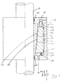
- the clamping device according to Figure 1 consists of the positionally fixed (111, 111 ') of the Rod 21 sealed (112, 112 ') passes through housing 11, which is supported on rod 21, leaving sufficient distance from each other regularly over the Circumference of the rod 21 distributed clamping segments 12 and one surrounding the clamping segments 12 Axially displaceable (double arrow A) clamping bush 13 while leaving of free spaces 113, 114 on the end faces of the clamping bush 13, on the outer surface 131 of the clamping bushing 13 supports via seals 117, 117 '.
- the corresponding ones Surfaces 121, 132 of the clamping segments 12 and the clamping bush 13 are designed conically in the opposite direction, a conicity being selected that is sufficient Ensures self-locking between the clamping segments 12 and the clamping bush 13, about 5 ° in the case shown.
- a plurality of ring grooves 133 are formed in the contact surface 132 of the clamping bush 13 .
- Behind the clamping bush 13 is a unpressurized space 116 formed by seals 117, 117 '.
- the clamping bush 13 (arrow A ') is the clamping bush 13 of one of the clamping bushes 13 employment tendency mediated spring 14, the spring chamber 114 is then can also be pressurized (31).
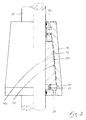
- the clamping device shown in Figure 2 differs from that shown in Figure 1 Device only in that the effective spring-side pressure application surface 134 of the clamping bush 113 is designed to be larger than the opposite pressure application surface 136. This results in the support of the instead of the effect on the clamping bush 13 acting springs 14 by the pressure medium fed into the spring chamber 114 to widen the clamping bush 13.
Landscapes
- Engineering & Computer Science (AREA)
- General Engineering & Computer Science (AREA)
- Mechanical Engineering (AREA)
- Jigs For Machine Tools (AREA)
- Clamps And Clips (AREA)
- Discharging, Photosensitive Material Shape In Electrophotography (AREA)
- Shaping Of Tube Ends By Bending Or Straightening (AREA)
Claims (13)
- Dispositif de serrage pour pièces cylindriques, déplaçables dans la direction axiale ou tournantes (barres ou arbres), constitué de segments de serrage (12) avec conicité extérieure, qui sont répartis sur son pourtour et qui viennent s'appliquer contre la barre ou l'arbre (21), d'un manchon de serrage (13) qui enserre les segments de serrage (12) et qui est déplaçable dans la direction axiale par rapport aux segments de serrage (12) et qui présente une conicité en sens contraire de sa surface d'application (132) contre les segments de serrage (12) qui provoque un auto-blocage, ainsi que d'un boítier (11) tenant la pression, qui enserre les segments de serrage (12) et le manchon de serrage (13) et qui prend appui contre la barre ou l'arbre (21) par des garnitures d'étanchéité, en laissant un espace libre (113, 114) des deux côtés, avec des ressorts (14) qui agissent sur une extrémité du manchon de serrage (13), qui prennent appui contre le boítier (11) et qui confèrent au manchon de serrage (13) une tendance au serrage, ainsi qu'avec un accès (31) du fluide sous pression à la chambre de ressort (114), caractérisé par un manchon de serrage (13) qui prend appui à ses deux extrémités contre le boítier (11), par des bagues d'étanchéité (117, 117') et qui peut être desserré par une pression de fluide sous pression à appliquer aux deux extrémités.
- Dispositif de serrage selon la revendication 1, caractérisé en ce que la surface d'attaque de la pression du manchon de serrage (13) est plus grande côté chambre de ressort (114) qu'à l'autre extrémité (113).
- Dispositif de serrage selon la revendication 1 ou la revendication 2, caractérisé en ce que dans l'une des surfaces correspondantes des segments de serrage (12) et du manchon de serrage (13), sont formés des retraits (133) régulièrement répartis sur la surface et qui sont accessibles à partir de la chambre de ressort (114).
- Dispositif de serrage selon la revendication 3, caractérisé par des retraits sous la forme de rainures radiales (133).
- Dispositif de serrage selon l'une des revendications 1 à 4, caractérisé en ce qu'un espace libre (116) délimité de manière étanche à la pression est formé entre le boítier (11) et le manchon de serrage (13).
- Dispositif de serrage selon l'une des revendications 1 à 5, caractérisé par une conicité ≤ à 5°.
- Dispositif de serrage selon l'une des revendications 1 à 6, caractérisé par une pluralité de pistons de déverrouillage (16) qui passent dans le boítier (11), sont régulièrement répartis sur le pourtour du manchon de serrage (13) et qui peuvent être alimentés en fluide sous pression.
- Dispositif de serrage selon l'une des revendications 1 à 6, caractérisé par un piston de déverrouillage annulaire qui passe dans le boítier (11), qui agit sur le manchon de serrage (13) et qui peut être alimenté en fluide sous pression.
- Dispositif de serrage pour pièces cylindriques, déplaçables dans la direction axiale ou tournantes (barres ou arbres), constitué de segments de serrage (12) avec conicité extérieure (121) ainsi que d'un boítier (41) qui enserre les segments de serrage (12), qui prend appui, par des garnitures d'étanchéité, contre la barre ou l'arbre (21), en laissant un espace libre des deux côtés, avec conicité en sens contraire de sa surface d'application (141) contre les segments de serrage (12), avec une conicité provoquant un auto-blocage, avec des ressorts (14) qui agissent sur une extrémité, sur les segments de serrage (12) déplaçables dans la direction axiale, qui prennent appui contre le boítier (41) et qui confèrent aux segments de serrage (12) une tendance au serrage, ainsi qu'avec un accès (31) du fluide sous pression à la chambre de ressort (114), les segments de serrage (12) pouvant être desserrés par une pression du fluide sous pression à appliquer aux deux extrémités.
- Dispositif de serrage selon la revendication 9, caractérisé en ce que les ressorts de serrage (14) prennent appui contre les segments de serrage (12), par un disque annulaire.
- Dispositif de serrage selon la revendication 9 ou 10, caractérisé par des pistons qui passent dans le boítier (14), qui soutiennent l'action des ressorts de serrage (14), qui viennent s'appliquer contre les segments de serrage (12) et qui peuvent être alimentés en fluide sous pression.
- Dispositif de serrage selon l'une des revendications 1 à 11, caractérisé par un boítier (11 ou 41) fixé dans sa position.
- Dispositif de serrage selon l'une des revendications 1 à 11, caractérisé par un boítier (11 ou 41), qui tourne avec l'arbre (21), avec des arrivées de fluide sous pression par des raccords tournants.
Applications Claiming Priority (2)
| Application Number | Priority Date | Filing Date | Title |
|---|---|---|---|
| DE19508175 | 1995-03-09 | ||
| DE19508175A DE19508175A1 (de) | 1995-03-09 | 1995-03-09 | Klemmvorrichtung für zylindrische, in achsialer Richtung verlagerbare oder drehende Teile |
Publications (2)
| Publication Number | Publication Date |
|---|---|
| EP0731284A1 EP0731284A1 (fr) | 1996-09-11 |
| EP0731284B1 true EP0731284B1 (fr) | 2001-06-13 |
Family
ID=7756005
Family Applications (1)
| Application Number | Title | Priority Date | Filing Date |
|---|---|---|---|
| EP96103638A Expired - Lifetime EP0731284B1 (fr) | 1995-03-09 | 1996-03-08 | Collier de verrouillage pour éléments cylindriques |
Country Status (3)
| Country | Link |
|---|---|
| EP (1) | EP0731284B1 (fr) |
| AT (1) | ATE202189T1 (fr) |
| DE (2) | DE19508175A1 (fr) |
Families Citing this family (8)
| Publication number | Priority date | Publication date | Assignee | Title |
|---|---|---|---|---|
| DE19728457B4 (de) * | 1997-07-03 | 2004-01-15 | Ringfeder Vbg Gmbh | Hydraulisch spannbares Element zum kraftschlüssigen Verbinden eines zylindrischen Bauteils mit einem dazu konzentrisch angeordneten Körper |
| DE19736132A1 (de) * | 1997-08-20 | 1999-03-04 | Daimler Benz Ag | Klemmvorrichtung für ein axial bewegliches Bauteil |
| DE10350225A1 (de) | 2003-10-27 | 2005-05-19 | Sitema Gmbh & Co. Kg | Feststellvorrichtung |
| DE102006004659A1 (de) | 2006-01-31 | 2007-08-02 | Sitema Gmbh & Co. Kg | Klemmvorrichtung |
| DE102010021859B4 (de) * | 2010-05-28 | 2012-05-03 | Schunk Gmbh & Co. Kg Spann- Und Greiftechnik | Brems- und/oder Feststellvorrichtung eines auf einer Schiene verfahrbaren Schlittens |
| DE102010027152B4 (de) * | 2010-07-14 | 2019-03-28 | Jean-Claude Montandon | Spannvorrichtung zum Spannen eines Werkstücks |
| CN102954323B (zh) * | 2012-11-12 | 2015-06-03 | 华南理工大学 | 一种用于柔顺机构微动平台的可控楔块预紧机构 |
| CN104912937A (zh) * | 2015-06-20 | 2015-09-16 | 苏州蓝王机床工具科技有限公司 | 易于拆卸的轴套结构 |
Family Cites Families (4)
| Publication number | Priority date | Publication date | Assignee | Title |
|---|---|---|---|---|
| DE1804857B2 (de) * | 1968-10-24 | 1971-11-25 | Hänchen, Siegfried, 7304 Ruit | Vorrichtung zur klemmung einer axial verschiebbaren kolben stange |
| CH567191A5 (en) * | 1973-07-03 | 1975-09-30 | Humes Ltd | Securing hub to shaft by friction - created by hydraulically driving conical sleeve between hub and shaft |
| DE4126897A1 (de) * | 1991-08-14 | 1993-02-18 | Rexroth Mannesmann Gmbh | Hydraulisches klemmsystem |
| US5492430A (en) * | 1994-10-14 | 1996-02-20 | Carl A. Hammoms | Telescopic tubes locking device |
-
1995
- 1995-03-09 DE DE19508175A patent/DE19508175A1/de not_active Withdrawn
-
1996
- 1996-03-08 EP EP96103638A patent/EP0731284B1/fr not_active Expired - Lifetime
- 1996-03-08 DE DE59607059T patent/DE59607059D1/de not_active Expired - Fee Related
- 1996-03-08 AT AT96103638T patent/ATE202189T1/de not_active IP Right Cessation
Also Published As
| Publication number | Publication date |
|---|---|
| DE59607059D1 (de) | 2001-07-19 |
| DE19508175A1 (de) | 1996-09-12 |
| ATE202189T1 (de) | 2001-06-15 |
| EP0731284A1 (fr) | 1996-09-11 |
Similar Documents
| Publication | Publication Date | Title |
|---|---|---|
| EP0214192B1 (fr) | Joint sous forme de brosses | |
| DE3138032A1 (de) | Verbesserte kupplung und bremse und verbesserte universalkupplung | |
| EP0731284B1 (fr) | Collier de verrouillage pour éléments cylindriques | |
| EP0253981A1 (fr) | Dispositif pour convoyer des bandes | |
| DE2206261A1 (de) | Vorrichtung zum Befestigen (Einspannen) und Vorspannen von Kreissägeblättern | |
| DE102009022206B3 (de) | Lagerung mit einer Brems- und/oder Klemmvorrichtung | |
| DE19645228C2 (de) | Luftfeder mit Abrollkörper | |
| EP0640764B1 (fr) | Compresseur à piston | |
| DE3000637A1 (de) | Loesbare kraftschluessige befestigung einer welle in einer nabe | |
| DE3212785C3 (de) | Offenend-spinnrotor | |
| DE3040359A1 (de) | Als waermetauscher dienende walze | |
| DE2600569C3 (de) | Spielfreie Lageranordnung für Wellenlagerungen | |
| DE7616304U1 (de) | Achsialkolbenpumpe | |
| DE19910541C1 (de) | Vorrichtung zur Montage, Sicherung und Demontage eines auf einer fliegend gelagerten Walzenwelle verspannten Walzrings | |
| DE2406151B2 (de) | Nabenverbindung zwischen einer nabe und einer welle | |
| DE8137709U1 (de) | Druckmaschine | |
| DE2418164B2 (de) | Innenbeströmte Radialkolbenmaschine | |
| DE69925908T2 (de) | Eine Hydraulische rotierende Axialkolbenmaschine | |
| DE29614242U1 (de) | Antriebswelle aus faserverstärktem Kunststoffrohr mit angeklemmten Anschlußeinrichtungen | |
| DE4438931C2 (de) | Hydrolager | |
| CH623894A5 (en) | Hydraulic screw machine | |
| EP0340338B1 (fr) | Raccord de tuyau | |
| CH656842A5 (de) | Einrichtung zur bremsenbetaetigung. | |
| AT230683B (de) | Dichtungsanordnung zwischen zwei wenigstens im wesentlichen koaxial angeordneten gegeneinander beweglichen Körpern | |
| DE2716728C2 (de) | Scheibenrefiner |
Legal Events
| Date | Code | Title | Description |
|---|---|---|---|
| PUAI | Public reference made under article 153(3) epc to a published international application that has entered the european phase |
Free format text: ORIGINAL CODE: 0009012 |
|
| AK | Designated contracting states |
Kind code of ref document: A1 Designated state(s): AT CH DE FR GB IT LI |
|
| 17P | Request for examination filed |
Effective date: 19970304 |
|
| 17Q | First examination report despatched |
Effective date: 19981222 |
|
| GRAG | Despatch of communication of intention to grant |
Free format text: ORIGINAL CODE: EPIDOS AGRA |
|
| GRAG | Despatch of communication of intention to grant |
Free format text: ORIGINAL CODE: EPIDOS AGRA |
|
| GRAH | Despatch of communication of intention to grant a patent |
Free format text: ORIGINAL CODE: EPIDOS IGRA |
|
| GRAH | Despatch of communication of intention to grant a patent |
Free format text: ORIGINAL CODE: EPIDOS IGRA |
|
| GRAA | (expected) grant |
Free format text: ORIGINAL CODE: 0009210 |
|
| AK | Designated contracting states |
Kind code of ref document: B1 Designated state(s): AT CH DE FR GB IT LI |
|
| PG25 | Lapsed in a contracting state [announced via postgrant information from national office to epo] |
Ref country code: IT Free format text: LAPSE BECAUSE OF FAILURE TO SUBMIT A TRANSLATION OF THE DESCRIPTION OR TO PAY THE FEE WITHIN THE PRESCRIBED TIME-LIMIT;WARNING: LAPSES OF ITALIAN PATENTS WITH EFFECTIVE DATE BEFORE 2007 MAY HAVE OCCURRED AT ANY TIME BEFORE 2007. THE CORRECT EFFECTIVE DATE MAY BE DIFFERENT FROM THE ONE RECORDED. Effective date: 20010613 Ref country code: GB Free format text: LAPSE BECAUSE OF FAILURE TO SUBMIT A TRANSLATION OF THE DESCRIPTION OR TO PAY THE FEE WITHIN THE PRESCRIBED TIME-LIMIT Effective date: 20010613 Ref country code: FR Free format text: LAPSE BECAUSE OF FAILURE TO SUBMIT A TRANSLATION OF THE DESCRIPTION OR TO PAY THE FEE WITHIN THE PRESCRIBED TIME-LIMIT Effective date: 20010613 |
|
| REF | Corresponds to: |
Ref document number: 202189 Country of ref document: AT Date of ref document: 20010615 Kind code of ref document: T |
|
| REF | Corresponds to: |
Ref document number: 59607059 Country of ref document: DE Date of ref document: 20010719 |
|
| GBV | Gb: ep patent (uk) treated as always having been void in accordance with gb section 77(7)/1977 [no translation filed] |
Effective date: 20010613 |
|
| EN | Fr: translation not filed | ||
| PG25 | Lapsed in a contracting state [announced via postgrant information from national office to epo] |
Ref country code: AT Free format text: LAPSE BECAUSE OF NON-PAYMENT OF DUE FEES Effective date: 20020308 |
|
| PG25 | Lapsed in a contracting state [announced via postgrant information from national office to epo] |
Ref country code: LI Free format text: LAPSE BECAUSE OF NON-PAYMENT OF DUE FEES Effective date: 20020331 Ref country code: CH Free format text: LAPSE BECAUSE OF NON-PAYMENT OF DUE FEES Effective date: 20020331 |
|
| PLBE | No opposition filed within time limit |
Free format text: ORIGINAL CODE: 0009261 |
|
| STAA | Information on the status of an ep patent application or granted ep patent |
Free format text: STATUS: NO OPPOSITION FILED WITHIN TIME LIMIT |
|
| 26N | No opposition filed | ||
| REG | Reference to a national code |
Ref country code: CH Ref legal event code: PL |
|
| PGFP | Annual fee paid to national office [announced via postgrant information from national office to epo] |
Ref country code: DE Payment date: 20030527 Year of fee payment: 8 |
|
| PG25 | Lapsed in a contracting state [announced via postgrant information from national office to epo] |
Ref country code: DE Free format text: LAPSE BECAUSE OF NON-PAYMENT OF DUE FEES Effective date: 20041001 |