EP0731370A2 - Optischer Stecker - Google Patents
Optischer Stecker Download PDFInfo
- Publication number
- EP0731370A2 EP0731370A2 EP96301636A EP96301636A EP0731370A2 EP 0731370 A2 EP0731370 A2 EP 0731370A2 EP 96301636 A EP96301636 A EP 96301636A EP 96301636 A EP96301636 A EP 96301636A EP 0731370 A2 EP0731370 A2 EP 0731370A2
- Authority
- EP
- European Patent Office
- Prior art keywords
- optical fiber
- housing
- optical
- joining
- protrusion
- Prior art date
- Legal status (The legal status is an assumption and is not a legal conclusion. Google has not performed a legal analysis and makes no representation as to the accuracy of the status listed.)
- Withdrawn
Links
- 230000003287 optical effect Effects 0.000 title claims abstract description 43
- 239000013307 optical fiber Substances 0.000 claims abstract description 76
- 230000013011 mating Effects 0.000 claims abstract description 18
- 238000000034 method Methods 0.000 description 10
- 230000000717 retained effect Effects 0.000 description 5
- 230000001681 protective effect Effects 0.000 description 4
- 230000005540 biological transmission Effects 0.000 description 3
- RZVAJINKPMORJF-UHFFFAOYSA-N Acetaminophen Chemical compound CC(=O)NC1=CC=C(O)C=C1 RZVAJINKPMORJF-UHFFFAOYSA-N 0.000 description 1
- 230000006866 deterioration Effects 0.000 description 1
- 230000014759 maintenance of location Effects 0.000 description 1
- 230000003014 reinforcing effect Effects 0.000 description 1
- 230000035939 shock Effects 0.000 description 1
Images


Classifications
-
- G—PHYSICS
- G02—OPTICS
- G02B—OPTICAL ELEMENTS, SYSTEMS OR APPARATUS
- G02B6/00—Light guides; Structural details of arrangements comprising light guides and other optical elements, e.g. couplings
- G02B6/24—Coupling light guides
- G02B6/42—Coupling light guides with opto-electronic elements
- G02B6/4292—Coupling light guides with opto-electronic elements the light guide being disconnectable from the opto-electronic element, e.g. mutually self aligning arrangements
-
- G—PHYSICS
- G02—OPTICS
- G02B—OPTICAL ELEMENTS, SYSTEMS OR APPARATUS
- G02B6/00—Light guides; Structural details of arrangements comprising light guides and other optical elements, e.g. couplings
- G02B6/24—Coupling light guides
- G02B6/36—Mechanical coupling means
- G02B6/38—Mechanical coupling means having fibre to fibre mating means
- G02B6/3807—Dismountable connectors, i.e. comprising plugs
- G02B6/3833—Details of mounting fibres in ferrules; Assembly methods; Manufacture
- G02B6/3847—Details of mounting fibres in ferrules; Assembly methods; Manufacture with means preventing fibre end damage, e.g. recessed fibre surfaces
- G02B6/3849—Details of mounting fibres in ferrules; Assembly methods; Manufacture with means preventing fibre end damage, e.g. recessed fibre surfaces using mechanical protective elements, e.g. caps, hoods, sealing membranes
-
- G—PHYSICS
- G02—OPTICS
- G02B—OPTICAL ELEMENTS, SYSTEMS OR APPARATUS
- G02B6/00—Light guides; Structural details of arrangements comprising light guides and other optical elements, e.g. couplings
- G02B6/24—Coupling light guides
- G02B6/36—Mechanical coupling means
- G02B6/38—Mechanical coupling means having fibre to fibre mating means
- G02B6/3807—Dismountable connectors, i.e. comprising plugs
- G02B6/389—Dismountable connectors, i.e. comprising plugs characterised by the method of fastening connecting plugs and sockets, e.g. screw- or nut-lock, snap-in, bayonet type
- G02B6/3893—Push-pull type, e.g. snap-in, push-on
Definitions
- This invention relates to optical connectors used for the connection of optical fibers to optical elements.
- Optical connectors are usually used for the connection of optical fibers to optical elements. These optical connectors consist of a first housing retaining an optical fiber and a second housing retaining an optical element. The optical fiber is usually retained by means of a ferrule surrounding the optical fiber, and the optical fiber surrounded by the ferrule is secured in the first housing by means of a so-called harness. Sometimes, the front end of the optical fiber can be damaged in the process of the handling of this harness which results in deterioration of the transmission characteristics and in an inaccurate transmission of the optical signals.
- a method intended to prevent the front end of the optical fiber surrounded by a ferrule from damage is shown in Japanese Utility Model Disclosure Sho 63 (1988)-128511.
- the ferrule is secured in the housing in such a manner that the front end of the optical fiber is recessed from the front end of the housing, and the connection of the front end of the optical fiber and the optical element is accomplished by means of a short optical fiber or other optical transmission medium. While this method makes it possible to prevent the front end of the optical fiber form damage during the handling of the harness, it produces additional surfaces of connection between the short optical fiber and the optical fiber secured by the harness and between the short optical fiber and the optical element, which results in an increase in the attenuation of the optical signals transmitted through the connector.
- Another method of solving this problem consists of providing a spring biased protective member enclosing the front end of the optical fiber and biased forward, farther than the front end of the optical fiber.
- the protective member is pushed back as shown in Japanese Patent Disclosure Hei 1(1989)-316711.
- the blasing spring is made rather strong so that it would be impossible to push the protective member back by a tool or some other item.
- such a design requires a high mating force to push the spring biased protective member back in order to expose the optical fiber ends.
- Another disadvantage of this method is that it requires additional parts.
- An object of this invention is to provide an optical connector having relatively few parts and providing protection for the front end of the optical fiber.
- an optical connector having a first housing, an optical riber protection member, and a second housing
- the first housing having a joining cavity with bosses formed on the inside walls extending in a mating direction which is intended for the retention of an optical fiber inserted in this joining section in the direction of connection and secured in this inserted position.
- the optical fiber protection member having a base with a through opening through which an optical fiber is inserted, having at least one leg extending from the base in the mating direction and latching with the abovementioned bosses, which can be inserted in and withdrawn from the joining section.
- the second housing having a joining protrusion fitting into the joining cavity equipped with thrust protrusions formed on the outside wall, which retains an optical element to which an optical fiber is connected.
- the optical fiber protection member is located in the first housing such that the front end of the optical fiber is inside the through opening because the legs and the bosses are engaged.
- the legs and bosses are released from each other due to the fact that when the joining protrusion is inserted in the joining cavity, the thrust protrusions bend the legs.
- the front end of the optical fiber is protected due to the fact that the front end of the optical fiber is located inside the through opening of the protection member which is retained inside the first housing because the legs of the optical fiber protection member are engaged with the bosses of the first housing. Since the bosses of the first housing are made on the inside wall of the joining cavity, it is impossible to disengage the legs from the bosses even using tools.
- the optical connector according to this invention makes it possible to protect the front end of the optical fiber by using the optical fiber protection member, while keeping the number of parts in the connector relatively small.
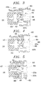
- Figure 1 shows an exploded perspective view of the optical connector according to a first embodiment of this invention.
- Figure 2 shows a cross sectional view of the optical connector of Fig. 1 in the assembled condition.
- Figures 3 - 5 shows cross sectional views of the first and the second housings in the process of connection: In Figure 3, the first and the second housings at the very beginning of mating; in Figure 4, the first and the second housings are shown in an advanced position of mating; Figure 5 shows the first and the second housings in the fully mated position.
- Figure 6 shows an exploded three-dimensional view of the optical connector according to the second embodiment of this invention.
- Figure 7 shows a cross sectional view of the optical connector of Fig. 6 in the assembled condition.
- the optical connector 10 consists of a first housing or plug housing 20 having a joining cavity 22 with bosses 22a and 22b formed on the inside walls 20a and extending in the mating direction indicated by the arrow 12; an optical fiber protection member 40 which can be inserted in and withdrawn from the joining cavity 22 having a plate-shaped base 42; and a second housing, or header housing 60 having a joining protrusion 62 which fits in the joining cavity 22.
- a through opening 26 is provided through which the optical fiber 24 is inserted and retained.
- a ferrule 28 is secured on the front end of the optical fiber 24 and fixed by a retainer 30. This provides for the protection of the front end of the optical fiber 24.
- a holder 70 is attached by means of latching projections 34 and secured by a cover 80 which is attached by means of cover latching projections 72.
- a ring 36 is crimped around the reinforcing sleeve of the optical fiber 24.
- the section between this ring 36 and the holder 70 has a spring 38. This spring 38 biases the optical fiber in the mating direction.
- through holes 74 and 82 are provided for the optical fiber 24.
- the base 42 of the optical fiber protection member 40 has a through opening 42a for the optical fiber 24.
- the optical fiber protection member 40 has a pair of L-shaped legs 44 and U-shaped legs 46 extending from the right and left sides of the base 42 in the mating direction. As it will be explained below, L-shaped legs 44 are intended to engage with bosses 22a, and U-shaped legs 46 with bosses 22b.
- the optical fiber protection member 40 has two guiding rods 48 extending from the base 42 opposite the direction. The function of these guiding rods 48 is to prevent the optical fiber protection member 40 from skewing.
- the joining protrusion 62 of the header housing 60 has thrust protrusions 66 (see Fig. 3) formed on the outside walls 64.
- the optical element 68 intended for the connection with the optical fiber 24 is housed in the header housing 60.
- the header housing 60 also has mounting sections 69 intended for the fixing the connector to a board (not shown in the drawing).
- Fig 2 depicts a state when the plug housing 20 and the header housing 60 are completely disengaged from each other.
- the optical fiber protection member 40 is retained in the plug housing 20 with the front end of the optical fiber 24 (see Fig. 1) being located inside the through opening 42a due to the fact that the L-shaped legs 44 are engaged with the bosses 22a.
- the movement of the optical fiber protection member 40 in the mating direction is prevented by the fact that the U-shaped legs 46 are engaged with the bosses 22c formed on the inside wall 20a. Due to such an arrangement, the front end of the optical fiber is reliably protected prior to the connection of the plug housing 20 and the header housing 60.
- Fig. 3 depicts a position when the plug housing 20 and the header housing 60 just start to be mated.
- the front edge of the thrust protrusions 66 is wedged between the ends of the L-shaped legs 44.
- the optical fiber protection member 40 When the connection progresses even farther (to a position shown in Fig. 5), the optical fiber protection member 40 is pushed inside by the joining protrusion 62. The connection is completed when the engagement of the U-shaped legs 46 and the bosses 22b is released. At this time, the optical fiber 24 comes in contact with the optical element 68, and they become optically connected.
- the header housing 60 is removed from the plug housing 20, the back edge of the thrust protrusion 66 engages with the L-shaped legs 44, and after the optical fiber protection member 40 is returned to its original position (Fig. 3), the protrusion separates the L-shaped legs 44, and comes out of the engagement. Therefore, it is possible to return the optical fiber protection member 40 to its original position without a separate spring.
- the thrust protrusion 66 shown in Figs. 3 - 5, by solid lines is extended above the plane of the paper, another thrust protrusion 66 is formed on the opposite side of the joining protrusion.
- Fig. 6 is an exploded three-dimensional view of the second embodiment of the optical connector according to this invention
- Figure 7 is a cross sectional view of the optical connector shown in Fig. 6 in the assembled state.
- the optical connector according to the second embodiment of this invention has even fewer parts. Components which are common to the optical connector 10 shown in Fig. 1 are designated the same numbers.
- the optical fiber protection member 40 and the header housing 60 are the same as in Fig. 1.
- the process of connection of the plug housing 120 and the header housing 60 is the same as shown in Figs. 2 - 5.
- the optical connector 100 consists of a plug housing 120 having a joining cavity 22 with bosses 22a and 22b formed on the inside walls 120a and extending in the mating direction indicated by the arrow 12, an optical fiber protection member 40 , and a header housing 60.
- the optical fiber 124 is retained inside the joining cavity 22 of the plug housing 120 so that it extends in the mating direction.
- the front end of the optical fiber 124 is mounted in the ferrule 28 and is secured in the retainer 30 protecting the front end of the optical fiber 124.
- slots are provided for the holder 170 which prevents the spring 38 from falling off.
- Flap 135 is provided to maintain the holder 170 in place in the plug housing 120 during the use of the connector 100.
- the optical connectors 10, 100 makes it possible to prevent the front end of the optical fiber, 24, 124 from damage by placing it through a through opening 42a of the optical fiber protection member 40, that is, it makes it possible to protect the front end of the optical fiber 24, 124 while having fewer parts.
Landscapes
- Physics & Mathematics (AREA)
- General Physics & Mathematics (AREA)
- Optics & Photonics (AREA)
- Mechanical Coupling Of Light Guides (AREA)
Applications Claiming Priority (2)
| Application Number | Priority Date | Filing Date | Title |
|---|---|---|---|
| JP7051231A JPH08248264A (ja) | 1995-03-10 | 1995-03-10 | 光コネクタ |
| JP51231/95 | 1995-03-10 |
Publications (2)
| Publication Number | Publication Date |
|---|---|
| EP0731370A2 true EP0731370A2 (de) | 1996-09-11 |
| EP0731370A3 EP0731370A3 (de) | 1998-03-25 |
Family
ID=12881181
Family Applications (1)
| Application Number | Title | Priority Date | Filing Date |
|---|---|---|---|
| EP96301636A Withdrawn EP0731370A3 (de) | 1995-03-10 | 1996-03-11 | Optischer Stecker |
Country Status (5)
| Country | Link |
|---|---|
| US (1) | US5608829A (de) |
| EP (1) | EP0731370A3 (de) |
| JP (1) | JPH08248264A (de) |
| KR (1) | KR960035071A (de) |
| CN (1) | CN1159003A (de) |
Families Citing this family (13)
| Publication number | Priority date | Publication date | Assignee | Title |
|---|---|---|---|---|
| US5802228A (en) * | 1996-12-16 | 1998-09-01 | Lucent Technologies Inc. | Optical package with removable fiber termination |
| US6154597A (en) * | 1998-01-05 | 2000-11-28 | Molex Incorporated | Fiber optic termination system including a fiber optic connector assembly and method of fabricating same |
| US5915058A (en) * | 1998-01-05 | 1999-06-22 | Molex Incorporated | Fiber optic connector assembly |
| US6081647A (en) * | 1998-01-05 | 2000-06-27 | Molex Incorporated | Fiber optic connector receptacle |
| US6076976A (en) * | 1998-03-27 | 2000-06-20 | General Motors Corporation | Fiber optic cable connector |
| US5909526A (en) * | 1998-04-08 | 1999-06-01 | Molex Incorporated | Fiber optic connector assembly |
| US6079881A (en) * | 1998-04-08 | 2000-06-27 | Molex Incorporated | Fiber optic connector receptacle assembly |
| US20030040790A1 (en) * | 1998-04-15 | 2003-02-27 | Furst Joseph G. | Stent coating |
| JP2001108870A (ja) * | 1999-10-06 | 2001-04-20 | Mitsubishi Electric Corp | 光デバイス及びその製造方法 |
| US6832858B2 (en) * | 2002-09-13 | 2004-12-21 | Teradyne, Inc. | Techniques for forming fiber optic connections in a modularized manner |
| WO2005047946A1 (en) * | 2003-11-03 | 2005-05-26 | Teradyne, Inc. | Techniques for forming fiber optic connections in a modularized manner |
| JP4922636B2 (ja) * | 2006-03-24 | 2012-04-25 | オリンパスメディカルシステムズ株式会社 | 内視鏡 |
| CN104216056B (zh) * | 2013-06-03 | 2016-08-10 | 深圳日海通讯技术股份有限公司 | 一种光纤连接器插头及多芯光纤连接器 |
Family Cites Families (7)
| Publication number | Priority date | Publication date | Assignee | Title |
|---|---|---|---|---|
| JPH063489B2 (ja) * | 1985-12-14 | 1994-01-12 | 日本電気株式会社 | 光フアイバコネクタ |
| EP0339876B1 (de) * | 1988-04-25 | 1994-01-12 | The Whitaker Corporation | Steckeraufbau mit beweglicher Schutzverkleidung |
| US5016968A (en) * | 1989-09-27 | 1991-05-21 | At&T Bell Laboratories | Duplex optical fiber connector and cables terminated therewith |
| JPH05224087A (ja) * | 1992-02-17 | 1993-09-03 | Sumitomo Electric Ind Ltd | 光線路の接続構造 |
| US5245683A (en) * | 1992-08-21 | 1993-09-14 | Molex Incorporated | Board mounted fiber optic connector |
| FR2696840B1 (fr) * | 1992-10-09 | 1994-11-18 | Souriau & Cie | Fiche encliquetable de connexion de fibre optique, notamment fiche monobloc surmoulée. |
| US5419717A (en) * | 1994-08-15 | 1995-05-30 | The Whitaker Corporation | Hybrid connector between optics and edge card |
-
1995
- 1995-03-10 JP JP7051231A patent/JPH08248264A/ja not_active Withdrawn
-
1996
- 1996-02-27 KR KR1019960004786A patent/KR960035071A/ko not_active Withdrawn
- 1996-03-08 CN CN96101884A patent/CN1159003A/zh active Pending
- 1996-03-11 EP EP96301636A patent/EP0731370A3/de not_active Withdrawn
- 1996-03-11 US US08/596,904 patent/US5608829A/en not_active Expired - Fee Related
Also Published As
| Publication number | Publication date |
|---|---|
| JPH08248264A (ja) | 1996-09-27 |
| KR960035071A (ko) | 1996-10-24 |
| EP0731370A3 (de) | 1998-03-25 |
| CN1159003A (zh) | 1997-09-10 |
| US5608829A (en) | 1997-03-04 |
Similar Documents
| Publication | Publication Date | Title |
|---|---|---|
| US5588080A (en) | Connector for connecting an optical fiber cable | |
| EP1014126B1 (de) | Steckeranordnung | |
| US5741150A (en) | Unitary spring latch for an electrical connector assembly | |
| US5553180A (en) | Adapter assembly for fiber optic connectors | |
| KR920001120B1 (ko) | 소켓트, 플러그 및 광학 접속기 | |
| KR0182255B1 (ko) | 래칭 기구를 구비한 커넥터 조립체 | |
| EP0997753B1 (de) | Faseroptische Verbindungseinheit | |
| EP0117022B1 (de) | Faseroptische Verbindungsanordnung | |
| EP0758099B1 (de) | Adapteranordnung für faseroptische Verbinder | |
| US6019521A (en) | Optical fiber connector | |
| US7413351B2 (en) | Optical connection apparatus which has a shutter and which can be designed to be small in size | |
| KR100321627B1 (ko) | 광섬유 커넥터 조립체 | |
| US5608829A (en) | Optical connector having optical fiber protection member | |
| US8011834B2 (en) | Optical connector plug | |
| EP1092995B1 (de) | Optischer Steckverbinder mit mehreren Modulgehäusen | |
| US6497516B1 (en) | Guide pin for optical fiber connectors and optical fiber connector plug | |
| EP0848267B1 (de) | Faseroptische Verbinderbaugruppe | |
| KR20020006480A (ko) | 광섬유 커넥터용 정렬 시스템 | |
| US6964526B2 (en) | Optical plug and optical connector provided with the optical plug | |
| US6741783B2 (en) | Optical cable adapter or connector | |
| US6206580B1 (en) | Optical connector | |
| US6364686B2 (en) | Electrical and/or optical connector with a latching arm | |
| JPH05119239A (ja) | 多心光コネクタ | |
| JPH04102809A (ja) | 光コネクタ | |
| CN110888198A (zh) | 光纤衰减器 |
Legal Events
| Date | Code | Title | Description |
|---|---|---|---|
| PUAI | Public reference made under article 153(3) epc to a published international application that has entered the european phase |
Free format text: ORIGINAL CODE: 0009012 |
|
| AK | Designated contracting states |
Kind code of ref document: A2 Designated state(s): DE FR GB IT NL |
|
| 17P | Request for examination filed |
Effective date: 19961122 |
|
| PUAL | Search report despatched |
Free format text: ORIGINAL CODE: 0009013 |
|
| AK | Designated contracting states |
Kind code of ref document: A3 Designated state(s): DE FR GB IT NL |
|
| RHK1 | Main classification (correction) |
Ipc: G02B 6/38 |
|
| STAA | Information on the status of an ep patent application or granted ep patent |
Free format text: STATUS: THE APPLICATION HAS BEEN WITHDRAWN |
|
| 18W | Application withdrawn |
Withdrawal date: 19980918 |