EP0731418A2 - Méthode et appareil d'identification et de localisation d'un objet - Google Patents
Méthode et appareil d'identification et de localisation d'un objet Download PDFInfo
- Publication number
- EP0731418A2 EP0731418A2 EP96103089A EP96103089A EP0731418A2 EP 0731418 A2 EP0731418 A2 EP 0731418A2 EP 96103089 A EP96103089 A EP 96103089A EP 96103089 A EP96103089 A EP 96103089A EP 0731418 A2 EP0731418 A2 EP 0731418A2
- Authority
- EP
- European Patent Office
- Prior art keywords
- image
- camera
- light source
- light
- recognized
- Prior art date
- Legal status (The legal status is an assumption and is not a legal conclusion. Google has not performed a legal analysis and makes no representation as to the accuracy of the status listed.)
- Withdrawn
Links
Images


Classifications
-
- G—PHYSICS
- G06—COMPUTING OR CALCULATING; COUNTING
- G06V—IMAGE OR VIDEO RECOGNITION OR UNDERSTANDING
- G06V10/00—Arrangements for image or video recognition or understanding
- G06V10/10—Image acquisition
- G06V10/12—Details of acquisition arrangements; Constructional details thereof
- G06V10/14—Optical characteristics of the device performing the acquisition or on the illumination arrangements
- G06V10/145—Illumination specially adapted for pattern recognition, e.g. using gratings
Definitions
- the invention relates to a method and a device for identifying and locating an object.
- Such a method and such a device serve to automatically identify an object and to determine its exact position, and thus belong to the area of active detection systems which can recognize predetermined structural features of the object, in addition to the identification and determination of the position of the object , in particular in relation to the position of another object, for example a moving steered object such as of a vehicle or a robot arm.
- a typical application of the method and the device according to the invention is the automatic determination of the coordinates of an object or a load which is to be picked up by a driverless transport vehicle.
- the load must be recognized and its position first determined so that the vehicle can be steered into a predetermined position in which it can pick up the load.
- Another area of application of the method and the device according to the invention is the control of production machines in which certain workpieces are to be identified, localized and processed or certain tools are to be identified, localized and used.
- the object on which the invention is based is to create a method and a device for identifying and locating an object which work with simple means and are therefore inexpensive.
- the method and the device according to the invention are particularly suitable for identifying objects with a pronounced edge structure, the geometry of which is fixed. From the different physical Possibilities for recognizing such structures, namely the ultrasound method, the high-frequency method and the optical method, the optical method was chosen because edges can be detected with greater accuracy the shorter the wavelength of the information carrier, ie the source of the active system. In addition, inexpensive components are available on the market for optical processes, so that high accuracy can be combined with high economic efficiency.
- a major problem with the optical recording of objects and the processing of the corresponding images is that the resulting signal is always influenced by the illumination of the object, the illumination of the surroundings and other sources of light interference, such as lamps or sunlight. If the lighting conditions of the captured image are not constant, which is always the case in outdoor applications, the result is also a non-constant image of the object in question in an environment with changing lighting conditions. This makes the identification of an object with an optical image processing method considerably more difficult.
- disturbing light sources and influences from changing illuminations of the object or changing light conditions in the surroundings are completely eliminated by generating an image of the object in which it is in front of an artificially generated dark background without objects and light sources in the surroundings appears in a constant figure.
- An image processing can then be carried out in a simple manner, with which the object is identified and localized. Since essentially only the edges of the object have to be used for this purpose, it is sufficient to have a binary image or black and white image of the object to be recognized To create an object from the captured image that is completely independent of the environment and excludes all sources of interference.
- FIG. 1a, 1b and 1c show side or end views of objects which can be recognized with the method and the device described below. These objects have a distinctive edge structure, the geometry of which is fixed. This edge structure results from the fact that cavities filled with air are present on the inside and the body of the object is precisely delimited inside and outside.
- the structure shown in FIG. 1c corresponds, for example, to that of a transport pallet picked up by forklifts can be.
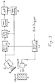
- the basic principle of the detection of such an object is that the object is recorded by a video camera without and with the artificial lighting of a controlled light source, the image from the video camera is stored in an image memory, a difference image is generated and the difference image obtained is then determined Way is processed.
- a video camera 2 is provided for this purpose, which is designed and arranged in such a way that it captures an image of a spatial area which is suspected to have the object 1 to be recognized on a certain part.
- the output signal of the video camera 2, ie the video data, is located in an image memory 5.
- a light source 4 can be switched on via a time control 10 which can be triggered from the outside and which is arranged and designed such that it illuminates only the part on which the object to be recognized 1 is suspected.
- the timing control 10 is also connected to the image memory 5 and causes the image of the video camera 2 to be stored in the image memory 5 without artificial lighting shortly before the light source 4 is switched off, so that it is at a differential stage 6.
- the video image of the camera 2 recorded in real time ie the image with artificial lighting by the light source 4, is then directly at the differential stage 6.
- the time interval between the saving of the image of the video camera 2 and the switching off of the light source 4 can be, for example, 1 s lie and is predetermined in the time control 10.
- the storage of the image of the video camera 2 is completed before the light source 4 is switched on.
- the difference image formed by the difference stage 6 is applied to a comparator 7 which, from the gray image coming from the difference stage 6, produces a black and white image, that is, a binary image is generated by comparing the gray values with an input comparison value that is close to the black value, in particular approximately 50% of the minimum gray value.
- the output signal of the comparator 7 is applied to an image signal processor 9 which, for example, uses a mask process to identify the object and then to determine its position precisely.
- image signal processor 9 uses a mask process to identify the object and then to determine its position precisely.
- the binary image of the comparator 7 is compared with masks stored in the microprocessor 9, which represent the basic structures of the object to be identified and located. The appropriate mask is slid over the object in the binary image and the coordinates of the position of the object are then determined from its position.
- the image processing in the microprocessor 9 can be clocked via a clock generator 8, which generates the clock signals required for this from the output signals of the video camera 2, for example from the synchronization signals contained therein. In this way, synchronous image processing in the microprocessor 9 is achieved. However, the image processing in the microprocessor can also take place asynchronously.
- a special filter 3 is placed, which is selected so that the spectral characteristic of the arrangement of filter and video camera on the one hand differs significantly from the spectral distribution of natural daylight and on the other hand fits the spectral distribution of the light source as well as possible .
- filter 3 is a bandpass filter with a central wavelength of likewise 800 nm and a width of approximately 50 nm is selected. This band pass is indicated in Fig. 4 by a hatched frame. Filters with such a bandpass filter are available on the market as so-called interference filters.
- the matching light source 4 should have a spectral light distribution that is in the range of the filter characteristic, as is shown by the hatched distribution curve in FIG. 4.
- laser light sources or sources based on infrared light-emitting diodes meet this condition, they are currently out of the question for practical use due to cost reasons or a lack of sufficient radiation power on the object to be illuminated.
- An inexpensive solution is therefore the use of a headlight as the light source 4, which has a lamp which has a color temperature of approximately 2900 ° K.
- the spectral distribution of the light from such a light source is not entirely in the filter area of FIG. 4, it has higher energy components in this wavelength region than the sunlight with the corresponding power, which results in a sufficient distinction in practice between natural sunlight and artificial lighting .
- a source of interference that shines into the camera e.g. the sun.
- the camera signal is read into the image memory 5 at a certain point in time triggered by an external trigger signal, so that a dark image arises in the following difference stage 6 as a difference image, since the image contents of the output image of the image memory 5 and of the image subsequently recorded in real time the camera 2 are the same at this time.
- the artificial light source 4 is then switched on, which is arranged and designed in such a way that it illuminates only the part of the spatial area recorded by the camera 2 in which the object 1 is suspected, then an image signal with a occurs at the output of the differential stage 6 Amplitude that corresponds to the artificially illuminated object and its surroundings.
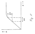
- this difference amplitude results from an additional change ⁇ E in the illuminance caused by the source 4.
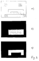
- This difference image is shown in FIG. 2b and is a gray image of the object in question, in which other objects and the interference light source have already been eliminated.
- the immediate area of the object to be recognized lies in FIG. 2b against an almost dark background.
- the light distribution of the light source 4 is adapted to this tolerance field.
- a binary image or black-and-white image is generated from the output gray image of the differential stage 6, which is shown in FIG. 2c and in which the structure of the object appears in black and white values.
- This binary image signal is input into the microprocessor 9 and processed into information about the identity of the object and its position coordinates by means of a known mask method using stored masks which reflect the basic structure of the object. Such image processing is possible with a simple algorithm due to the selected preprocessing in the differential stage 6 and in the comparator 7.
- the camera 2 and the light source 4 are arranged such that the light source 4 is directed perpendicularly to the object, while the camera 2 takes an image at an angle of about 45 ° from above, as shown in Fig. 3.
- This ensures that the cavity always has a contrast to the edges surrounding it, which are then easy to grasp, and that this edge of the object can also be recognized obliquely from front to back even when an even horizontal edge of the object is arranged. because information about all three spatial coordinates is available.
- the forklift can be pre-positioned so that it is already placed near the location where the pallet to be picked is suspected.
- the image processing described above is then used to determine whether a pallet is actually located at this point and what exact position the pallet is in relation to the forklift.
- the forklift can be controlled so that it moves with its fork into the cavities provided for the pallet in order to lift it.
- the method described above and the device described above work via a very simple, fast and inexpensive image processing which enables the identification and localization of workpieces or transport pallets with high accuracy.
Landscapes
- Engineering & Computer Science (AREA)
- Artificial Intelligence (AREA)
- Computer Vision & Pattern Recognition (AREA)
- Physics & Mathematics (AREA)
- General Physics & Mathematics (AREA)
- Multimedia (AREA)
- Theoretical Computer Science (AREA)
- Length Measuring Devices By Optical Means (AREA)
Applications Claiming Priority (2)
| Application Number | Priority Date | Filing Date | Title |
|---|---|---|---|
| DE19507812 | 1995-03-06 | ||
| DE19507812A DE19507812A1 (de) | 1995-03-06 | 1995-03-06 | Verfahren und Vorrichtung zum Identifizieren und Lokalisieren eines Objektes |
Publications (1)
| Publication Number | Publication Date |
|---|---|
| EP0731418A2 true EP0731418A2 (fr) | 1996-09-11 |
Family
ID=7755782
Family Applications (1)
| Application Number | Title | Priority Date | Filing Date |
|---|---|---|---|
| EP96103089A Withdrawn EP0731418A2 (fr) | 1995-03-06 | 1996-02-29 | Méthode et appareil d'identification et de localisation d'un objet |
Country Status (2)
| Country | Link |
|---|---|
| EP (1) | EP0731418A2 (fr) |
| DE (1) | DE19507812A1 (fr) |
Cited By (3)
| Publication number | Priority date | Publication date | Assignee | Title |
|---|---|---|---|---|
| WO1999004378A1 (fr) * | 1997-07-19 | 1999-01-28 | Footfall Limited | Systeme d'imagerie video |
| WO1999044178A1 (fr) * | 1998-02-27 | 1999-09-02 | Societe Industrielle D'aviation Latecoere | Dispositif de surveillance d'une enceinte, notamment de la soute d'un avion |
| US6529132B2 (en) | 1998-02-27 | 2003-03-04 | Societe Industrielle D'avation Latecoere | Device for monitoring an enclosure, in particular the hold of an aircraft |
Families Citing this family (3)
| Publication number | Priority date | Publication date | Assignee | Title |
|---|---|---|---|---|
| DE19718390A1 (de) * | 1997-04-30 | 1998-11-05 | Sick Ag | Opto-elektronischer Sensor |
| DE19809210A1 (de) * | 1998-03-04 | 1999-09-16 | Siemens Ag | Verfahren und Vorrichtung zur Überwachung einer Szene |
| DE102004036104A1 (de) * | 2004-07-24 | 2006-03-16 | Cognis Ip Management Gmbh | Vorrichtung und Verfahren zur Überwachung von Produktionsanlagen |
Family Cites Families (2)
| Publication number | Priority date | Publication date | Assignee | Title |
|---|---|---|---|---|
| DE3731947A1 (de) * | 1987-09-23 | 1989-04-13 | Kurt Dr Sauerwein | Verfahren und vorrichtung zum feststellen und auswerten von oberflaechenrissen bei werkstuecken |
| DE4009912A1 (de) * | 1990-03-28 | 1991-10-02 | Grundig Emv | Videokontroll-einrichtung |
-
1995
- 1995-03-06 DE DE19507812A patent/DE19507812A1/de not_active Ceased
-
1996
- 1996-02-29 EP EP96103089A patent/EP0731418A2/fr not_active Withdrawn
Cited By (4)
| Publication number | Priority date | Publication date | Assignee | Title |
|---|---|---|---|---|
| WO1999004378A1 (fr) * | 1997-07-19 | 1999-01-28 | Footfall Limited | Systeme d'imagerie video |
| WO1999044178A1 (fr) * | 1998-02-27 | 1999-09-02 | Societe Industrielle D'aviation Latecoere | Dispositif de surveillance d'une enceinte, notamment de la soute d'un avion |
| FR2775534A1 (fr) * | 1998-02-27 | 1999-09-03 | D Aviat Latecoere Soc Ind | Dispositif de surveillance d'une enceinte, notamment de la soute d'un avion |
| US6529132B2 (en) | 1998-02-27 | 2003-03-04 | Societe Industrielle D'avation Latecoere | Device for monitoring an enclosure, in particular the hold of an aircraft |
Also Published As
| Publication number | Publication date |
|---|---|
| DE19507812A1 (de) | 1996-09-12 |
Similar Documents
| Publication | Publication Date | Title |
|---|---|---|
| EP1027235B1 (fr) | Dispositif et procede pour la detection d'objets se trouvant sur un pare-brise | |
| EP2365890B1 (fr) | Procédé et dispositif de surveillance d'un processus d'usinage au laser exécuté sur une pièce, ainsi que tête d'usinage au laser équipée d'un tel dispositif | |
| EP2569757B1 (fr) | Système d'analyse et/ou de suivi de mouvements | |
| DE69426175T2 (de) | Verarbeitungsgerät zur Nachführung eines Videosignals | |
| DE2649224A1 (de) | System zur identifizierung eines charakteristischen merkmals einer flaeche | |
| DE102014002134A1 (de) | Vorrichtung zur Erkennung einer Beleuchtungsumgebung eines Fahrzeugs und Steuerungsverfahren davon | |
| DE2351400B2 (de) | Erkennungs-Einrichtung zum Erfassen gewisser gegenüber ihrer Umgebung kontrastierender Gegenstände | |
| DE2702452C2 (de) | Einrichtung zur Lagebestimmung eines einen anderen Remissionsgrad als der Hintergrund aufweisenden Objektes | |
| DE102007033835A1 (de) | Bildaufnahmetechnik zur direkten Objektsegmentierung in Bildern | |
| EP2276585A1 (fr) | Procédé pour la détection optique d'objets en mouvement | |
| EP1158460A2 (fr) | Système et procédé de traitement d'images | |
| DE102016216795A1 (de) | Verfahren zur Ermittlung von Ergebnisbilddaten | |
| EP1404119B1 (fr) | Module de caméra et procédé de prise d'images électroniques | |
| EP0731418A2 (fr) | Méthode et appareil d'identification et de localisation d'un objet | |
| EP1543471B1 (fr) | Detection et prise d'objets | |
| EP0448803B1 (fr) | Système de commande d'affichage vidéo | |
| DE68912154T2 (de) | Optisches Standortbestimmungs- und -messsystem für Raumfahrzeuge. | |
| EP1845336A1 (fr) | Procédé et dispositif pour la détection optique des objets en mouvement | |
| DE10018366A1 (de) | Optoelektronische Sensoranordnung sowie Verfahren zum Betreiben einer optoelektronischen Sensoranordnung | |
| EP0194630A2 (fr) | Procédé pour l'identification et/ou la localisation d'un objet | |
| CH616508A5 (fr) | ||
| DE2908483C2 (fr) | ||
| EP1156445B1 (fr) | Méthode de reconnaissance d'objet et caméra numérique utilisant cette méthode | |
| DE4419395A1 (de) | Verfahren und Einrichtung zur Analyse und Verarbeitung von Farbbildern | |
| EP0231004B1 (fr) | Procédé pour l'autocontrôle d'une installation de détection de fissures, en particulier par la méthode des poudres magnétiques |
Legal Events
| Date | Code | Title | Description |
|---|---|---|---|
| PUAI | Public reference made under article 153(3) epc to a published international application that has entered the european phase |
Free format text: ORIGINAL CODE: 0009012 |
|
| AK | Designated contracting states |
Kind code of ref document: A2 Designated state(s): DE DK ES FR GB SE |
|
| STAA | Information on the status of an ep patent application or granted ep patent |
Free format text: STATUS: THE APPLICATION IS DEEMED TO BE WITHDRAWN |
|
| 18D | Application deemed to be withdrawn |
Effective date: 19981008 |