EP0731423A1 - Technique de masquage arbitraire pour le remplissage de formes dans un moniteur - Google Patents
Technique de masquage arbitraire pour le remplissage de formes dans un moniteur Download PDFInfo
- Publication number
- EP0731423A1 EP0731423A1 EP95307330A EP95307330A EP0731423A1 EP 0731423 A1 EP0731423 A1 EP 0731423A1 EP 95307330 A EP95307330 A EP 95307330A EP 95307330 A EP95307330 A EP 95307330A EP 0731423 A1 EP0731423 A1 EP 0731423A1
- Authority
- EP
- European Patent Office
- Prior art keywords
- printer
- fill pattern
- mask
- pattern
- steps
- Prior art date
- Legal status (The legal status is an assumption and is not a legal conclusion. Google has not performed a legal analysis and makes no representation as to the accuracy of the status listed.)
- Granted
Links
Images



Classifications
-
- G—PHYSICS
- G06—COMPUTING OR CALCULATING; COUNTING
- G06K—GRAPHICAL DATA READING; PRESENTATION OF DATA; RECORD CARRIERS; HANDLING RECORD CARRIERS
- G06K15/00—Arrangements for producing a permanent visual presentation of the output data, e.g. computer output printers
-
- G—PHYSICS
- G06—COMPUTING OR CALCULATING; COUNTING
- G06T—IMAGE DATA PROCESSING OR GENERATION, IN GENERAL
- G06T11/00—Two-dimensional [2D] image generation
- G06T11/40—Filling planar surfaces by adding surface attributes, e.g. adding colours or textures
-
- G—PHYSICS
- G06—COMPUTING OR CALCULATING; COUNTING
- G06K—GRAPHICAL DATA READING; PRESENTATION OF DATA; RECORD CARRIERS; HANDLING RECORD CARRIERS
- G06K2215/00—Arrangements for producing a permanent visual presentation of the output data
- G06K2215/0002—Handling the output data
- G06K2215/0005—Accepting output data; Preparing data for the controlling system
- G06K2215/0008—Downloading generic data
-
- G—PHYSICS
- G06—COMPUTING OR CALCULATING; COUNTING
- G06K—GRAPHICAL DATA READING; PRESENTATION OF DATA; RECORD CARRIERS; HANDLING RECORD CARRIERS
- G06K2215/00—Arrangements for producing a permanent visual presentation of the output data
- G06K2215/0002—Handling the output data
- G06K2215/0005—Accepting output data; Preparing data for the controlling system
- G06K2215/0011—Accepting output data; Preparing data for the controlling system characterised by a particular command or data flow, e.g. Page Description Language, configuration commands
Definitions
- This invention relates to graphics processing and in particular to a method for filling in an arbitrary shape with a selected pattern for display.
- control and display information from the host computer to the printer is provided in a high level page description language and then converted by the printer into a raster scan type format.
- the printer then applies the data in the raster scan format to the print engine for printing on a medium. Since the printer, and not the host computer, performs the processing of the high level commands, the computer is able to more quickly support the user.
- a page to be printed must be first stored in the printer as a display list or stored as individual pixels in a frame buffer.
- the HP DeskJet 1200C is a color inkjet type printer using a black pen, a cyan pen, a magenta pen, and a yellow pen. Drops of black ink or color ink are emitted by the inkjet printheads to form dots or pixels on the medium. These dots are closely spaced, or overlapping, and the individual dots are indistinguishable from one another. Many colors are created by the various combinations of cyan, magenta, and yellow ink.
- the page description language transmitted to the printer describes shapes to be displayed using coordinates and primitives such as rectangles, vectors, circles, or polygons. Text is described by designating characters and fonts rather than describing the appearance of the characters.
- the page description language also describes operations to be performed on the shapes, such as filling a shape with a particular pattern or color.
- Such a page description language is in contrast to a simple pixel-by-pixel description, where each pixel to be printed is transmitted to the printer in a raster scan order, although such a transmission in raster scan format is permitted in conjunction with the high level language.
- One well known page description language is the PCL-5C language, which is described in detail in the Hewlett-Packard publication entitled "PCL 5 Printer Language Technical Reference Manual," Manual Part No. 5961-0509, 1992, incorporated herein by reference. A programmer who is developing a graphics program may use such a PCL-5 language to define the images to be displayed.
- Other page description languages include PostScript and HP-GL/2,
- the amount of memory required in the printer and the time it takes to successfully render and print a page is directly proportional to the complexity of the page description.
- the memory capacity in the HP DeskJet 1200C is 2 megabytes but is expandable to up to 26 megabytes for more complex graphics.
- Graphics application programs for personal computers have made it easy for users to apply fills to text, arbitrary objects, and backdrops.
- a gradient fill the user has to just choose a beginning color, an end color, and the nature of the gradient, such as linear, angular, radial, or conical.
- the gradient Once the gradient is defined, it can be applied to any text or graphics object to fill in the text or object with the gradient pattern previously defined.
- Many applications dealing with presentation graphics now have full-screen gradients available as standard backdrops.
- GUI graphical user interfaces
- printer drivers used to interface a particular printer with a variety of application programs in the host computer
- page description languages to support the variety of filling or shading techniques used by the various application programs.
- ROP raster operation
- Figs. 1A-1C illustrate a conventional ROP process for creating an oval having a gradient fill. The process creates the gradient fill without changing any portion of the display outside of the boundaries of the arbitrary shape.
- the initial background is a color X background 10 which is stored in a display list or frame buffer.
- the user creates an arbitrary shape by, for example, drawing an outline of the shape using a mouse in conjunction with a conventional graphics program.
- This arbitrary shape may also be any object automatically created by the application program. It will be assumed that the arbitrary shape is an oval.
- the user next selects the desired fill for the arbitrary shape, which we will assume is a gradient pattern 12 of color Y.
- a three-step ROP process is then performed to now fill in the arbitrary shape with the selected fill pattern.
- the pixels in the background 10 destination area are exclusively ORed (XOR) with the gradient fill pattern 12.
- This step is designated ROP 90 in the page description language. This will produce an intermediate gradient pattern 14 of color Z in the destination area.
- step two the previously created arbitrary shape is copied as a monochrome mask 16 into the destination area (in either a display list or a frame buffer) to replace the corresponding pixels in the destination area, as illustrated by pattern 18.
- This copy step is designated ROP 240.
- step three all of the pixels in the destination area pattern 18 are then XORed with the gradient pattern 12 using the ROP 90 instruction again.
- the result of step three is that the portions outside of the mask 16 will be converted to the original display background 10, while the pixels within the mask 16 will be converted to the gradient pattern 12.
- the resulting masked gradient pattern 12 is then printed or otherwise displayed.
- the above three-step process requires the gradient pattern 12 to be transmitted twice, and requires sufficient memory in the printer to store this gradient pattern twice. If the fill pattern were a complex raster image (e.g., a picture), much more memory would be required to store this image.
- the conventional three-step ROP process for filling in arbitrary shapes with a pattern is modified to require less computation and memory.
- a printer driver routine installed in the host computer converts the conventional ROP instructions into a modified set of instructions which are then transmitted and processed by the printer.
- a masking buffer in the printer supports the process. The improved method only requires the fill pattern to be transmitted once to the printer instead of twice, resulting in memory savings of up to 50% and speeding up the print time significantly.
- the first step (ROP 90) of XORing the fill pattern with the destination area is deleted.
- the arbitrary shapes for being filled are transmitted to the printer, and these shapes (masks) are stored in a temporary masking buffer.
- the fill pattern is then transmitted to the printer and ANDed with the mask(s) so that only the fill pattern coinciding with the area of the mask(s) is forwarded for printing.
- a particular implementation of this method uses the PCL-5C format architecture and is implemented without any application intervention.
- the printer driver alters a conventional ROP process so as to operate with existing applications already using such an ROP process.
- the invention may also be implemented directly by the application programs so that no alteration by the printer driver is needed. Displaying the resulting image by other than printing is also contemplated.
- Figs. 1A-1C illustrate the pertinent steps in a conventional three-step ROPs process for filling in an arbitrary shape with a fill pattern.
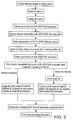
- Fig. 2 is a flow chart of the basic steps used in the preferred embodiment method for filling in an arbitrary shape.
- Figs. 3A and 3B illustrate selected steps being carried out during the preferred process of Fig. 2.
- Fig. 4 is a block diagram of a computer and printer system used to carry out one embodiment of the invention.
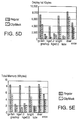
- Figs. 5A-5E are graphs comparing the processing speed and memory requirements of the preferred method to a conventional method.
- the invention will be described in the context of a host computer instructing a printer to display one or more arbitrary shapes having a fill pattern.
- the applications program e.g., a graphics program
- the host computer uses a conventional three-step ROPs process to fill in arbitrary shapes and that instructions to the printer are transmitted in a high level page description language.
- the construction of such a system will be described in greater detail with respect to Fig. 4.
- a software package is provided along with the printer and is loaded into the host computer to act as a printer driver.
- a printer driver is generally used to interface a particular printer with the various data formats expected to be encountered. It is the printer driver which then performs the various conversion steps described below before the printing instructions are transmitted. Certain hardware and software in the printer then performs the various actions described below on the transmitted instructions.
- the applications program run by the host computer implements the function of the printer driver directly so that conversion by the printer driver is not necessary.
- the printer instructions are transmitted to the printer in a PCL-5C format.
- the PCL-5C formatter architecture used by the printer is based on the construction of a display list of objects that are generated by a language parser from the incoming PCL-5C data stream.
- the parser recognizes commands in the data stream and performs the requested functions.
- the output of the parser is stored as a display list.
- the display list keeps growing until the page description is complete and the page closed.
- the objects and their attributes in the display list need not be created in the top-to-down order these objects appear on a page.
- the objects in the display list are then rasterized into 3-plane (CMY) swaths and passed to the print engine for actual printing, such as by cyan, magenta, and yellow inkjet printheads.
- CY 3-plane
- the display list also receives certain attributes, such as foreground color, pattern and ROPs, that characterize the nature of the display list objects in its rendering process.
- These state change attributes are stored in the printer until a source object comes along which is to be affected by the state change. The state changes are enqueued in the display list prior to the objects they affect.
- Such display list formats are well known.
- the instructions or states used in the preferred method are handled by the printer in the same way as, for example, a foreground color or a ROP, where all objects placed in the display list subsequent to a state change are acted upon by the state change instruction. Therefore, implementation of this invention requires little change in the overall operation of the printer electronics.
- an original display background 22 (Fig. 3A) of any pattern or color is presumed.
- the user then creates an arbitrary shape for being filled in using a conventional application program and a graphical user interface.
- This step of creating an arbitrary shape may instead be performed automatically by an application program.
- the arbitrary shape to be filled may include text or a raster image.
- the user or application program selects the fill pattern for the arbitrary shape and commands the computer to fill the arbitrary shape with the selected fill pattern.
- the fill pattern may be a solid color or a non-homogeneous pattern, such as a gradient or raster image.
- the application program will generate the first of the various ROP commands (ROP 90, ROP 240, ROP 90) described with respect to Fig. 1A in an attempt to instruct the printer to fill the arbitrary shape with the fill pattern.
- the printer driver which has been previously programmed into the host computer, detects the first instruction (ROP 90) from the application program. In response to this detection, the printer driver then discards all the objects (e.g., the fill pattern) that were sent with (or subsequent to) the XOR ROP 90 command.
- this fill pattern is not transmitted to the printer, and the first step shown in prior art Fig. 1A associated with the XOR ROP 90 command is not carried out by the printer. Therefore, the printer's memory does not have to store this information.
- the XOR ROP 90 command and fill pattern are transmitted to the printer but are ignored by the printer.
- the application program then generates the instructions for the second step in Fig. 1B, which is a mask copy command ROP 240.
- the printer driver intercepts this command and causes the escape sequence to enter the state of mask definition (ESC*l1p).
- This mask definition instruction ESC*l1P and the arbitrary mask 26 (Fig. 3) generated by the user are then transmitted to the printer.
- the printer places the mask 26 into a monochrome (single plane) masking buffer 30 (Fig. 4) at the printer resolution, as shown in Fig. 3A.
- the mask 26 shape may be defined using any of the well known PCL-5C primitives (e.g., vectors, polygons, text, or 1-bit raster).
- the printer driver When the application program generates the third instruction in the conventional three-step ROP process of Fig. 1C, which is a repeat of the XOR ROP 90 step, the printer driver generates a mask clipping instruction ESC*l2P.
- the mask 26 in the masking buffer 30 is logically ANDed with the fill pattern 32 (Fig. 3B) transmitted to the printer along with the ESC*l2P instruction.
- This step will cause the transmitted fill pattern 32 to be clipped by the mask 26 and thereby take the shape of the mask 26. This is referred to as inclusive clipping.
- the resulting arbitrarily shaped fill pattern 34 (Fig.
- 3B along with the original background 22 are then processed as a swath (if a display list is used) or stored in a frame buffer for later printing. If a display list is used, an image processor converts the data in the display list to a swath to be printed and transmits this swath of data to the print engine. The print engine then converts the swath to energization signals for the various pens used in the printer.
- the masking buffer 30 contents would first be inverted and then ANDed with the fill pattern 32 to clip all portions of the fill pattern 32 within the mask 26 boundaries. This is referred to as exclusive clipping.
- the arbitrary shape being filled is the portion of the display external to the mask.
- an instruction ESC*l0P is transmitted, causing the masking buffer 30 to be deallocated and the mask definition to be deactivated.
- the masking buffer 30 no longer affects the incoming graphics data.
- Masking buffer 30 may form a portion of a larger memory within the printer.
- the monochrome masking buffer 30 only needs to be as large as a single swath.
- the swath size is at least as wide as the printing width for one scan of the printer.
- the swath size may be multiple printing widths and is selected based upon a number of well known tradeoffs including processing time and printing speed. An object (or multiple objects) to be displayed may thus be broken up into a number of swaths when processed, depending on the size of the object.
- the resulting masked fill pattern 34 in Fig. 3B is thus identical to the arbitrarily shaped fill pattern 12 in Fig. 1C, but only two steps are used instead of the conventional three-step ROP process. Also, since the fill pattern is sent only once instead of twice, memory savings of up to 50% are achieved, and the processing time required before the printer may actually print the graphics is reduced significantly.
- the arbitrary masking process may be directly carried out by an application program which uses the arbitrary masking process instead of the ROP process of Figs. 1A-1C.
- the escape routine described with respect to Fig. 2 is not utilized, even though the escape routine may still be available in the printer driver for use with other application programs.
- the display device may instead be a display screen or other device.
- FIG. 4 is a simplified block diagram illustrating the various components of the preferred embodiment system.
- a conventional personal computer 40 is programmed with conventional operating system files 42 (such as MS-DOS), application files 44, graphical user interface (GUI) files (such as by Microsoft), and graphical device interface (GDI) files 46 (such as Windows by Microsoft).
- GUI graphical user interface
- GDI graphical device interface
- a conventional input device 48 such as a mouse or keyboard, as well as a conventional CRT 50 or other display screen, are connected to computer 40 in a conventional manner.
- the screen processor and frame buffer are shown in block 52.
- Printer driver files 56 are also loaded into computer 40 to perform the conversion from the conventional ROP fill instructions to the arbitrary masking instructions described with respect to Figs. 2 and 3 as well as to perform the conventional interface functions of a printer driver.
- a cable 58 carries the PCL-5C data from the computer 40 to the printer 60.
- the PCL-5C data is then suitably formatted and parsed by PCL formatter 62.
- the processed data is stored in a display list 64.
- the masking buffer 30, previously described, is used in conjunction with the display list 64 and the image processor 66 to generate rasterized black and three-plane CMY swaths. These swaths are passed on to the print engine 68 for printing. All components and functions not specifically addressed herein are well known and may be conventional, as is an inherent advantage of the present invention.
- a printer in accordance with this invention may also utilize a conventional frame buffer and associated processing hardware instead of display list 64.
- the detailed construction of such a printer would be known to those skilled in the art.
- printer electronics are shown external to the computer 40, the printer electronics (or other display electronics) may be housed internal to the computer 40.
- Figs. 5A-5E compare the performance in processing speed and memory savings of the inventive clip/mask technique versus the conventional ROP process. As seen by the various graphs, the display list objects and file size is significantly reduced using the clip/mask technique, and the simulation timing for processing data using the clip/mask technique is significantly reduced from the ROP process timing.
Landscapes
- Engineering & Computer Science (AREA)
- Physics & Mathematics (AREA)
- General Physics & Mathematics (AREA)
- Theoretical Computer Science (AREA)
- General Engineering & Computer Science (AREA)
- Image Generation (AREA)
- Record Information Processing For Printing (AREA)
Applications Claiming Priority (2)
| Application Number | Priority Date | Filing Date | Title |
|---|---|---|---|
| US08/399,403 US5642474A (en) | 1995-03-06 | 1995-03-06 | Arbitrary masking technique for filling in shapes for display |
| US399403 | 1995-03-06 |
Publications (2)
| Publication Number | Publication Date |
|---|---|
| EP0731423A1 true EP0731423A1 (fr) | 1996-09-11 |
| EP0731423B1 EP0731423B1 (fr) | 2002-01-16 |
Family
ID=23579374
Family Applications (1)
| Application Number | Title | Priority Date | Filing Date |
|---|---|---|---|
| EP95307330A Expired - Lifetime EP0731423B1 (fr) | 1995-03-06 | 1995-10-16 | Technique de masquage arbitraire pour le remplissage de formes dans un moniteur |
Country Status (4)
| Country | Link |
|---|---|
| US (1) | US5642474A (fr) |
| EP (1) | EP0731423B1 (fr) |
| JP (1) | JP3813229B2 (fr) |
| DE (1) | DE69525031T2 (fr) |
Cited By (1)
| Publication number | Priority date | Publication date | Assignee | Title |
|---|---|---|---|---|
| EP1698968A3 (fr) * | 2005-03-01 | 2007-06-06 | Canon Kabushiki Kaisha | Appareil de commande d'impression, son procédé de commande et pilot de dispositif |
Families Citing this family (18)
| Publication number | Priority date | Publication date | Assignee | Title |
|---|---|---|---|---|
| US6476924B1 (en) * | 1994-08-31 | 2002-11-05 | Canon Kk | Image processing apparatus and method for equalizing images outputted by different devices |
| US6024630A (en) * | 1995-06-09 | 2000-02-15 | Applied Materials, Inc. | Fluid-pressure regulated wafer polishing head |
| JP3229526B2 (ja) * | 1995-10-26 | 2001-11-19 | キヤノン株式会社 | 記録装置およびその記録データ処理方法 |
| US5854886A (en) * | 1996-03-29 | 1998-12-29 | Hewlett-Packard Company | Method and system for printing rasterized documents |
| US6320667B1 (en) * | 1996-12-27 | 2001-11-20 | Canon Kabushiki Kaisha | Information processing apparatus and method for transmitting printing information, and recording medium readable by a computer storing a program for transmitting printing information |
| US6039434A (en) * | 1997-03-04 | 2000-03-21 | Hewlett-Packard Company | Thresholded undercolor removal and black replacement in a thermal-inkjet printer or plotter |
| US6019454A (en) * | 1997-03-04 | 2000-02-01 | Hewlett-Packard Company | Multipass inkjet printmodes with randomized dot placement, to minimize patterning and liquid loading |
| US6082849A (en) * | 1997-03-10 | 2000-07-04 | Hewlett-Packard Company | Random printmasks in a multilevel inkjet printer |
| US6176566B1 (en) * | 1997-03-10 | 2001-01-23 | Hewlett-Packard Company | Cell-based text enhancement for a color printer by complete excess-color stripping, based on previous regions |
| JP3008943B1 (ja) | 1998-08-18 | 2000-02-14 | 富士ゼロックス株式会社 | 画像処理装置および画像処理方法 |
| JP3362674B2 (ja) | 1998-08-26 | 2003-01-07 | 富士ゼロックス株式会社 | 画像処理装置および画像処理方法 |
| US7133143B2 (en) * | 2001-12-21 | 2006-11-07 | Xerox Corporation | Printing method employing printer-independent print quality characteristics |
| JP3754975B2 (ja) * | 2003-11-18 | 2006-03-15 | キヤノン株式会社 | 情報処理装置及び情報処理方法 |
| US20050129308A1 (en) * | 2003-12-10 | 2005-06-16 | International Business Machines Corporation | Method, apparatus and program storage device for identifying a color of a displayed item using a non-color indicator |
| US20050264582A1 (en) * | 2004-05-27 | 2005-12-01 | Agfa Monotype Corporation | Method and system for application page description in print device color space |
| US8208169B2 (en) * | 2006-05-24 | 2012-06-26 | Lexmark International, Inc. | Method and system for rendering a transparent object in an image |
| US8098261B2 (en) * | 2006-09-05 | 2012-01-17 | Apple Inc. | Pillarboxing correction |
| JP5791256B2 (ja) * | 2010-10-21 | 2015-10-07 | キヤノン株式会社 | 表示制御装置、表示制御方法 |
Citations (4)
| Publication number | Priority date | Publication date | Assignee | Title |
|---|---|---|---|---|
| WO1991008548A1 (fr) * | 1989-12-06 | 1991-06-13 | Eastman Kodak Company | Systeme d'entree/sortie |
| WO1992001269A1 (fr) * | 1990-07-05 | 1992-01-23 | Eastman Kodak Company | Processeur d'images tramees pour imprimante adressable en tous points |
| EP0476533A2 (fr) * | 1990-09-14 | 1992-03-25 | Hughes Aircraft Company | Système programmable double de texturation de bloc et de découpage de complexe dans un processeur de rendu graphique |
| US5249061A (en) * | 1990-12-21 | 1993-09-28 | Canon Kabushiki Kaisha | Color image printer with adaptive color process |
Family Cites Families (2)
| Publication number | Priority date | Publication date | Assignee | Title |
|---|---|---|---|---|
| US4992956A (en) * | 1987-10-08 | 1991-02-12 | Advanced Micro Devices, Inc. | Apparatus for assembling data for supply to a scanning output device |
| US5003496A (en) * | 1988-08-26 | 1991-03-26 | Eastman Kodak Company | Page memory control in a raster image processor |
-
1995
- 1995-03-06 US US08/399,403 patent/US5642474A/en not_active Expired - Lifetime
- 1995-10-16 EP EP95307330A patent/EP0731423B1/fr not_active Expired - Lifetime
- 1995-10-16 DE DE69525031T patent/DE69525031T2/de not_active Expired - Fee Related
-
1996
- 1996-03-06 JP JP04895796A patent/JP3813229B2/ja not_active Expired - Fee Related
Patent Citations (4)
| Publication number | Priority date | Publication date | Assignee | Title |
|---|---|---|---|---|
| WO1991008548A1 (fr) * | 1989-12-06 | 1991-06-13 | Eastman Kodak Company | Systeme d'entree/sortie |
| WO1992001269A1 (fr) * | 1990-07-05 | 1992-01-23 | Eastman Kodak Company | Processeur d'images tramees pour imprimante adressable en tous points |
| EP0476533A2 (fr) * | 1990-09-14 | 1992-03-25 | Hughes Aircraft Company | Système programmable double de texturation de bloc et de découpage de complexe dans un processeur de rendu graphique |
| US5249061A (en) * | 1990-12-21 | 1993-09-28 | Canon Kabushiki Kaisha | Color image printer with adaptive color process |
Non-Patent Citations (1)
| Title |
|---|
| PARKHURST A D ET AL: "Connectivity of the HP DeskJet 1200C printer", HEWLETT-PACKARD JOURNAL, FEB. 1994, USA, vol. 45, no. 1, ISSN 0018-1153, pages 85 - 97, XP000426549 * |
Cited By (2)
| Publication number | Priority date | Publication date | Assignee | Title |
|---|---|---|---|---|
| EP1698968A3 (fr) * | 2005-03-01 | 2007-06-06 | Canon Kabushiki Kaisha | Appareil de commande d'impression, son procédé de commande et pilot de dispositif |
| US7706001B2 (en) | 2005-03-01 | 2010-04-27 | Canon Kabushiki Kaisha | Print control apparatus, control method thereof, and device driver for converting commands from one format to another |
Also Published As
| Publication number | Publication date |
|---|---|
| DE69525031D1 (de) | 2002-02-21 |
| JPH08263674A (ja) | 1996-10-11 |
| DE69525031T2 (de) | 2002-07-04 |
| US5642474A (en) | 1997-06-24 |
| EP0731423B1 (fr) | 2002-01-16 |
| JP3813229B2 (ja) | 2006-08-23 |
Similar Documents
| Publication | Publication Date | Title |
|---|---|---|
| US5642474A (en) | Arbitrary masking technique for filling in shapes for display | |
| EP0654759B1 (fr) | Appareil d'impression | |
| US5600768A (en) | Image generation with dynamically consolidated list of image data | |
| US6323958B1 (en) | Printing apparatus | |
| US5852679A (en) | Image processing apparatus and method | |
| US8054493B2 (en) | Optimizing raster operation functions during print job processing | |
| US6429950B1 (en) | Method and apparatus for applying object characterization pixel tags to image data in a digital imaging device | |
| US6456298B1 (en) | Image processing apparatus and method | |
| JP3175498B2 (ja) | インクジェット式カラー印刷のための黒色領域識別方式 | |
| JPH11298717A (ja) | 印刷システム | |
| JP3845045B2 (ja) | 画像処理装置、画像処理方法、画像形成装置、印刷装置及びホストpc | |
| JP2817687B2 (ja) | 画像形成装置 | |
| JPH08286860A (ja) | 出力制御方法及びその装置とそのコンピュータプログラム製品 | |
| US8208169B2 (en) | Method and system for rendering a transparent object in an image | |
| KR100396548B1 (ko) | 프린팅 속도를 향상시키는 프린터 제어 장치 및 그 방법 | |
| CN110618796A (zh) | 图像形成装置、其控制方法及存储其控制程序的存储介质 | |
| US6734987B1 (en) | Printer driver for generating a reduced printer description file | |
| JP3673536B2 (ja) | 印刷装置及び印刷方法 | |
| KR100440965B1 (ko) | 서로 다른 프린터 드라이버를 내장하여 인쇄 속도를향상시키는 프린팅 방법 및 그를 이용한 프린터 | |
| JPH07137353A (ja) | カラー印刷装置 | |
| JP2001324975A (ja) | 画像処理装置 | |
| JP2002024840A (ja) | 描画処理装置 | |
| JP2004021886A (ja) | 画像処理装置及び画像処理方法 | |
| JP3158101B2 (ja) | カラー画像処理装置およびカラー画像処理方法 | |
| JP2004358722A (ja) | 画像処理装置、描画データ処理方法及び該方法を実行するためのプログラム |
Legal Events
| Date | Code | Title | Description |
|---|---|---|---|
| PUAI | Public reference made under article 153(3) epc to a published international application that has entered the european phase |
Free format text: ORIGINAL CODE: 0009012 |
|
| AK | Designated contracting states |
Kind code of ref document: A1 Designated state(s): DE FR GB IT |
|
| 17P | Request for examination filed |
Effective date: 19970128 |
|
| 17Q | First examination report despatched |
Effective date: 19991217 |
|
| GRAG | Despatch of communication of intention to grant |
Free format text: ORIGINAL CODE: EPIDOS AGRA |
|
| RAP1 | Party data changed (applicant data changed or rights of an application transferred) |
Owner name: HEWLETT-PACKARD COMPANY, A DELAWARE CORPORATION |
|
| GRAG | Despatch of communication of intention to grant |
Free format text: ORIGINAL CODE: EPIDOS AGRA |
|
| GRAH | Despatch of communication of intention to grant a patent |
Free format text: ORIGINAL CODE: EPIDOS IGRA |
|
| GRAH | Despatch of communication of intention to grant a patent |
Free format text: ORIGINAL CODE: EPIDOS IGRA |
|
| GRAA | (expected) grant |
Free format text: ORIGINAL CODE: 0009210 |
|
| REG | Reference to a national code |
Ref country code: GB Ref legal event code: IF02 |
|
| AK | Designated contracting states |
Kind code of ref document: B1 Designated state(s): DE FR GB IT |
|
| REF | Corresponds to: |
Ref document number: 69525031 Country of ref document: DE Date of ref document: 20020221 |
|
| ET | Fr: translation filed | ||
| PLBE | No opposition filed within time limit |
Free format text: ORIGINAL CODE: 0009261 |
|
| STAA | Information on the status of an ep patent application or granted ep patent |
Free format text: STATUS: NO OPPOSITION FILED WITHIN TIME LIMIT |
|
| 26N | No opposition filed | ||
| PGFP | Annual fee paid to national office [announced via postgrant information from national office to epo] |
Ref country code: IT Payment date: 20061031 Year of fee payment: 12 |
|
| PGFP | Annual fee paid to national office [announced via postgrant information from national office to epo] |
Ref country code: DE Payment date: 20071130 Year of fee payment: 13 |
|
| PGFP | Annual fee paid to national office [announced via postgrant information from national office to epo] |
Ref country code: GB Payment date: 20071029 Year of fee payment: 13 Ref country code: FR Payment date: 20071017 Year of fee payment: 13 |
|
| GBPC | Gb: european patent ceased through non-payment of renewal fee |
Effective date: 20081016 |
|
| REG | Reference to a national code |
Ref country code: FR Ref legal event code: ST Effective date: 20090630 |
|
| PG25 | Lapsed in a contracting state [announced via postgrant information from national office to epo] |
Ref country code: IT Free format text: LAPSE BECAUSE OF NON-PAYMENT OF DUE FEES Effective date: 20071016 Ref country code: DE Free format text: LAPSE BECAUSE OF NON-PAYMENT OF DUE FEES Effective date: 20090501 |
|
| PG25 | Lapsed in a contracting state [announced via postgrant information from national office to epo] |
Ref country code: FR Free format text: LAPSE BECAUSE OF NON-PAYMENT OF DUE FEES Effective date: 20081031 |
|
| PG25 | Lapsed in a contracting state [announced via postgrant information from national office to epo] |
Ref country code: GB Free format text: LAPSE BECAUSE OF NON-PAYMENT OF DUE FEES Effective date: 20081016 |