EP0731611A2 - Gerät und Verfahren zur selektiven Verringerung einer Huffman-Kodierungsrate - Google Patents
Gerät und Verfahren zur selektiven Verringerung einer Huffman-Kodierungsrate Download PDFInfo
- Publication number
- EP0731611A2 EP0731611A2 EP96301476A EP96301476A EP0731611A2 EP 0731611 A2 EP0731611 A2 EP 0731611A2 EP 96301476 A EP96301476 A EP 96301476A EP 96301476 A EP96301476 A EP 96301476A EP 0731611 A2 EP0731611 A2 EP 0731611A2
- Authority
- EP
- European Patent Office
- Prior art keywords
- digital
- coding rate
- set forth
- current coding
- signal
- Prior art date
- Legal status (The legal status is an assumption and is not a legal conclusion. Google has not performed a legal analysis and makes no representation as to the accuracy of the status listed.)
- Withdrawn
Links
- 238000000034 method Methods 0.000 title claims abstract description 55
- 230000004044 response Effects 0.000 claims abstract description 5
- 238000012545 processing Methods 0.000 claims description 104
- 239000013598 vector Substances 0.000 claims description 38
- 230000005055 memory storage Effects 0.000 claims description 12
- 230000008569 process Effects 0.000 claims description 8
- 238000010586 diagram Methods 0.000 description 20
- 238000004891 communication Methods 0.000 description 17
- 238000007906 compression Methods 0.000 description 13
- 230000006835 compression Effects 0.000 description 13
- 238000005516 engineering process Methods 0.000 description 6
- 230000001413 cellular effect Effects 0.000 description 4
- 230000008859 change Effects 0.000 description 4
- 235000016068 Berberis vulgaris Nutrition 0.000 description 3
- 241000335053 Beta vulgaris Species 0.000 description 3
- 238000013139 quantization Methods 0.000 description 3
- 238000007792 addition Methods 0.000 description 2
- 238000013459 approach Methods 0.000 description 2
- 238000003491 array Methods 0.000 description 2
- 230000005540 biological transmission Effects 0.000 description 2
- 238000013144 data compression Methods 0.000 description 2
- 230000006872 improvement Effects 0.000 description 2
- 239000003550 marker Substances 0.000 description 2
- 230000005236 sound signal Effects 0.000 description 2
- 238000012935 Averaging Methods 0.000 description 1
- 230000004075 alteration Effects 0.000 description 1
- 238000013500 data storage Methods 0.000 description 1
- 230000003247 decreasing effect Effects 0.000 description 1
- 230000006870 function Effects 0.000 description 1
- 230000003287 optical effect Effects 0.000 description 1
- 230000008520 organization Effects 0.000 description 1
- 238000011946 reduction process Methods 0.000 description 1
- 239000004065 semiconductor Substances 0.000 description 1
- 230000003068 static effect Effects 0.000 description 1
- 238000006467 substitution reaction Methods 0.000 description 1
- 238000012546 transfer Methods 0.000 description 1
Images



Classifications
-
- H—ELECTRICITY
- H04—ELECTRIC COMMUNICATION TECHNIQUE
- H04N—PICTORIAL COMMUNICATION, e.g. TELEVISION
- H04N19/00—Methods or arrangements for coding, decoding, compressing or decompressing digital video signals
- H04N19/60—Methods or arrangements for coding, decoding, compressing or decompressing digital video signals using transform coding
-
- H—ELECTRICITY
- H04—ELECTRIC COMMUNICATION TECHNIQUE
- H04N—PICTORIAL COMMUNICATION, e.g. TELEVISION
- H04N19/00—Methods or arrangements for coding, decoding, compressing or decompressing digital video signals
- H04N19/10—Methods or arrangements for coding, decoding, compressing or decompressing digital video signals using adaptive coding
- H04N19/102—Methods or arrangements for coding, decoding, compressing or decompressing digital video signals using adaptive coding characterised by the element, parameter or selection affected or controlled by the adaptive coding
- H04N19/13—Adaptive entropy coding, e.g. adaptive variable length coding [AVLC] or context adaptive binary arithmetic coding [CABAC]
-
- H—ELECTRICITY
- H04—ELECTRIC COMMUNICATION TECHNIQUE
- H04N—PICTORIAL COMMUNICATION, e.g. TELEVISION
- H04N19/00—Methods or arrangements for coding, decoding, compressing or decompressing digital video signals
- H04N19/90—Methods or arrangements for coding, decoding, compressing or decompressing digital video signals using coding techniques not provided for in groups H04N19/10-H04N19/85, e.g. fractals
- H04N19/91—Entropy coding, e.g. variable length coding [VLC] or arithmetic coding
Definitions
- the present invention is related to United States Patent Application Serial No. 08/399,084, Attorney Docket No. Rosenberg 2, entitled “Apparatus and Methods for Determining an Initial Huffman Coding Rate”; United States Patent Application Serial No. 08/400,707, Attorney Docket No. Rosenberg 4, entitled “Apparatus and Methods for Performing Huffman Coding”; and United States Patent Application Serial No. 08/400,704, Attorney Docket No. Hartung 10-1, entitled “Method and Apparatus for Vector Quantization Caching in a Real Time Video Coder", which are all commonly assigned to the assignee of the present invention, and which are filed concurrently herewith.
- the disclosures of these related Applications are incorporated herein by reference.
- the present invention relates generally to signal compression, and in particular to apparatus and methods for selectively reducing a Huffman Coding rate.
- Conventional communication systems including networks, include two or more interconnected nodes wherein each node functions as a junction point within the system.
- Information is transferred between nodes using electric, light, and/or radio waves, and typically involves transferring one or more codewords.
- Each codeword represents a symbol in a symbol set, such as an alphabet, and includes data for use by, and/or instructions for, a receiving node.
- Each codeword is defined by one or more binary digits, or bits.
- Communication systems have limited bandwidth. In other words, there exists an upper limit, or maximum number, of bits which may be transferred per unit time. Contrary to this limitation is the need of many communication systems to transfer large quantities of symbols. This is particularly true in video applications, such as videophone and direct television, where video symbols typically represent chrominance and/or luminance values for picture elements ("pixels"), motion information, instructions indicating the content of the chrominance, and luminance values or marker codes. Marker codes are sync codes.
- Huffman Coding is one popular approach which is commonly used for video, audio/speech and high-speed data compression.
- Huffman Codes use variable length symbols wherein each symbol's length depends upon the probability of occurrence of the one or more codewords defining it.
- Each of the codewords used to represent the symbol set has a length inversely proportional to its symbol's usage. Assuming this symbol set is used in the English language, "wear” is likely to be said more often than “bear”, more often than “dart”, and more often than “beet”.
- the coding may accordingly be (be, dar, w, beet), where codeword length is equivalent to the number of letters.
- variable length codewords wherein common words such as ⁇ it, in, a, car, the, if, I, a, an) are shorter than words used less frequently, such as (approximately, university, automobile, individually, myself, particularly).
- Source entropy is an optimal "loss-less" coding rate, in other words, the smallest average number of bits per symbol required to represent a particular symbol set or alphabet.
- Huffman Coding techniques have been found to reduce coding rates to nearly source entropy.
- the probability of all occurrences of the various symbols tends to change as the video image changes. This causes the current Huffman Codes to be an inefficient representation of the symbols. Worse, these changes typically occur at random.
- the Huffman Codes accordingly cease to reduce coding rates to source entropy and require recalculation. This is often computationally difficult as the codeword for any one symbol depends on the probability of occurrence of the symbols in the alphabet. For large alphabets therefore each codeword, of which there are typically many, requires substantial computation.
- One conventional solution periodically recalculates the Huffman Codes.
- Another solution determines the source entropy, and then estimates from that determination the coding rate for recalculating the Huffman Codes.
- Each approach is typically inaccurate, and in many situations demands substantially the same processing resource requirements needed to recalculate the Huffman Codes as when originally defined.
- the inability of conventional communication systems to generate, and regenerate, Huffman Codes to maintain substantially source entropy remains a dominant obstacle to producing high quality video, audio/ speech and high-speed communication.
- Communication systems have limited bandwidth, i.e., a maximum rate at which bits may be transferred per a given time period.
- compression techniques and in particular Huffman Coding techniques, are incorporated into conventional signal compressing systems to increase information throughput, i.e., the number of codewords transferred given the available bandwidth.
- the present invention is directed to apparatus and methods for selectively reducing a coding rate in response to limited bandwidth in communication systems, including without limitation, processing system networks (including local and wide area networks), telephony systems (including videophone and cellular technologies), direct television systems, satellite systems, land-mobile radio systems, broadcast systems, data storage/retrieval systems, and the like, for example.
- processing system networks including local and wide area networks
- telephony systems including videophone and cellular technologies
- direct television systems satellite systems, land-mobile radio systems, broadcast systems, data storage/retrieval systems, and the like, for example.
- An apparatus in accordance with the principles of the present invention generates an output signal representing a selectively reduced coding rate for use in compressing a digital signal.
- the digital signal includes a plurality of digital sets wherein ones of the digital sets are non-unique.
- the apparatus includes receiving and processing means.
- the receiving means operates to receive an electric signal representing a current coding rate.
- the processing means operates to generate the output signal.
- the processing means selectively discards, or removes from consideration, one or more of the digital sets, preferably while the current coding rate is beyond a threshold coding rate, determines a coding rate difference resulting from the selectively discarded digital sets and recalculates the current coding rate using the rate difference.
- the output signal is then generated.
- a method in accordance with the principles of the present invention concerns selectively reducing a current coding rate for use in compressing a digital signal.
- the digital signal includes a plurality of digital sets wherein ones of the digital sets are non-unique.
- a current coding rate and a threshold coding rate are preferably compared to determine whether the current coding rate satisfies a predetermined criteria, i.e., such as validity.
- a predetermined criteria i.e., such as validity
- a coding rate difference resulting from selectively discarding ones of the digital sets is determined, and the current coding rate is recalculated using the determined rate difference.
- This selective reduction process preferably repeats until the current coding rate is valid, at which time the output signal is generated.
- One embodiment for using and/or distributing the present invention is as software.
- the software embodiment includes a plurality of processing system instructions which are stored to a storage medium.
- Preferred storage mediums include without limitation magnetic, optical, or semiconductor chip, as well as suitably arranged combinations thereof.
- the processing system instructions are readable by a processing system, and upon execution, operate to control at least one processing system for compressing a signal using Huffman Coding techniques in accordance with the principles of the present invention.
- FIG. 1 illustrates a block diagram of one exemplary system for compressing video signals in which the principles of the present invention are particularly advantageous.
- the exemplary system includes a conventional video camera 101 and a video processing board 102.
- Video processing board 102 includes an analog-to-digital (“A/D") converter 103, a video compression processor 104 and two conventional memory storage devices, namely, a dynamic random-access memory (“DRAM”) 105 and a static random-access memory (“SRAM”) 106.
- A/D analog-to-digital
- DRAM dynamic random-access memory
- SRAM static random-access memory
- Video camera 101 may suitably be connected to A/D converter 103 to convert analog video signals produced by video camera 101 to a representative digital signal.
- A/D converter 103 may suitably be connected to video compression processor 104.
- Video compression processor 104 preferably has associated with it DRAM 105 as well as SRAM 106. Compressed video signals produced by video compression processor 104 may be transmitted over a data line 107.
- camera 101 is a model no. YH-7B60, made by Sharp Corp., Osaka, Japan;
- A/D converter 103 is a model no. SAA7151, made by Philips' Gloeilampenfabrieken N.V., the Netherlands;
- Video compression processor 104 is a model no. VCP rev 3, made by Integrated Information Technologies Inc., Santa Clara, CA, USA.
- DRAM 105 and SRAM 106 are conventional suitably arranged storage devices.
- One preferred use of this video compression system is discussed in United States Patent Application Serial No. 08/400,704, Attorney Docket No. Hartung 10-1, which is commonly assigned to the assignee of the present invention and which is incorporated herein by reference.
- FIG. 2 illustrates an isometric view of an exemplary processing system 200 for compressing a video signal in accordance with the principles of the present invention.
- Processing system 200 is shown as a personal computer, and in one preferred embodiment is a model no. System 3333, by AT&T GIS, located in Dayton, Ohio.
- Processing system 200 may suitably be coupled with camera 101, and includes a hardware casing 201, having both a floppy disk drive 202 and a hard disk drive 203, a monitor 204 and a keyboard 205.
- Monitor 204 and keyboard 205 may be replaced by, or combined with, other conventional output and input devices, respectively.
- Floppy disk drive 202 is operable to receive, read and write to external disks.
- Hard disk drive 203 is operable to provide fast access storage and retrieval.
- Floppy disk drive 202 may be replaced by or combined with any conventional suitably arranged structure for receiving and transmitting data and instructions, including without limitation, tape and compact disc drives, telephony systems and devices (including videophone technologies), and serial and parallel ports.
- circuit boards such as video processing board 102 of FIG. 1 for example, may be included.
- Camera 101 is preferably coupled with processing system 200 through one of the aforementioned ports.
- input video images may be received via one or more separate storage devices, such as a floppy disk or a compact disc, for example.
- An important aspect of the exemplary embodiment therefore is that data and/or instruction collection and compression need not occur coincidentally.
- hardware casing 201 is illustrated with a cut-away portion which includes a processing unit 206 suitably coupled with a memory storage device 207.
- Memory storage device 207 may be a random access memory ("RAM”) or a read only memory (“ROM”), or other conventional suitably arranged memory storage device, such as DRAM 105 and/or SRAM 106 of FIG. 1 for example.
- processing system 200 is illustrated as having a single processing unit, a single hard disk drive and a single memory unit, processing system 200 may be equipped with a plurality of processing units and/or suitably arranged memory storage devices operable to cooperatively carry out the principles of the present invention.
- the present invention is particularly advantageous for use in video compression, the present invention is also well suited for use with other systems utilizing signal compression, including without limitation, processing system networks (including local and wide area networks), telephony systems (including videophone technologies), direct television systems, satellite systems, land-mobile radio systems, broadcast systems, information storage/retrieval systems, and the like.
- processing system networks including local and wide area networks
- telephony systems including videophone technologies
- direct television systems satellite systems
- land-mobile radio systems broadcast systems
- information storage/retrieval systems and the like.
- any processing system having conventional suitably arranged processing means for performing Huffman Coding in accordance with the principles of the present invention, including without limitation, cameras, videophones, telephones, televisions, sophisticated calculators and, hand-held, laptop/notebook, mini, mainframe and super computers, including RISC and parallel processing architectures, as well as within processing system network combinations of the foregoing.
- Conventional processing system architecture is more fully discussed in Computer Organization and Architecture, by William Stallings, MacMillan Publishing Co. (3rd ed. 1993), which is incorporated herein by reference.
- exemplary embodiments include, without limitation, implementations in firmware or hardware.
- Such exemplary embodiments may include suitably arranged circuitry, including programmable logic devices, such as PALs (programmable array logic), PLAs (programmable logic arrays) and DSPs (digital signal processors).
- PALs programmable array logic
- PLAs programmable logic arrays
- DSPs digital signal processors
- Other exemplary embodiments may also include FPGAs (field programmable gate arrays) and ASICs (application specific integrated circuits), for example.
- FPGAs field programmable gate arrays
- ASICs application specific integrated circuits
- FIG. 3 illustrates a block diagram of one exemplary microprocessing system which may be utilized in conjunction with processing system 200.
- the microprocessing system may be programmed to compress signals using Huffman Coding techniques in accordance with the principles of the present invention.
- the microprocessing system includes a single processing unit 206 coupled via data bus 303 with a single memory storage device 207.
- Memory storage device 207 is operable to store one or more processing system instructions which processing unit 206 is operable to retrieve and execute.
- Processing unit 206 includes a control unit 300, an arithmetic logic unit (“ALU") 301, and a local memory storage device 302, such as, stackable cache or a plurality of registers, for example.
- Control unit 300 is operable to fetch processing system instructions from memory storage device 207.
- ALU 301 is operable to perform a plurality of operations, including addition and Boolean AND needed to carry out those instructions.
- Local memory storage device 302 is operable to provide local high speed storage used for storing temporary results and
- FIG. 4a illustrates a block diagram of an exemplary video/ audio processing system in which the present invention is particularly advantageous.
- the exemplary system includes a single processing system 200, illustrated as a mainframe computer, coupled suitably with a plurality of conventional video cameras 401a-401n.
- Video cameras 401a-401n are positioned about a tennis stadium 402.
- Tennis stadium 402 includes two grand stands 403a, 403b and a tennis court 404.
- Each of the grand stands 403a, 403b includes a plurality of seats, some of which will be occupied by spectators 405 during a tennis match, as illustrated.
- Tennis court 404 is shown to include two tennis players 406a, 406b who oppose one another in the tennis match.
- One or more of the video cameras 401a-401n operate to capture the tennis match from which representative video and/or audio signals are produced.
- the produced signals are input to processing system 200 wherein they are processed and compressed using Huffman Coding techniques in accordance with the principles of the present invention to produce one or more output signals.
- the produced output signals are transmitted to a plurality of televisions 407a-407m.
- the televisions 407a-407m are located within a plurality of homes 408a-408m.
- FIG. 4b illustrates a block diagram of an exemplary processing system-based wireless local area network ("LAN") in which the present invention is particularly advantageous.
- the illustrated LAN includes two exemplary processing system nodes 200a, 200b, shown as personal computers. Each of the processing system nodes 200a, 200b is coupled suitably with a conventional antenna 409a, 409b, respectively, and includes videophone technologies (not shown). Antennas 409a, 409b operate to transmit and receive wireless communications between processing system nodes 200a, 200b. The received wireless communications are processed utilizing representative electric signals.
- the illustrated LAN facilitates communications between users A and B, 410a, 410b, respectively, wherein each processing system node is operable to send, receive, process and compress video, audio and high speed signals in accordance with the principles of the present invention.
- FIG. 4c illustrates a block diagram of an exemplary wireless communication system in which the present invention is particularly advantageous.
- the illustrated system includes a processing system 200, illustrated as a mainframe computer, which facilitates communication between a first node 411 and a second node 412.
- the first node 411 includes a first caller 413, shown utilizing a cellular telephone 414.
- the cellular telephone 414 is operable to send and receive wireless communication signals.
- the second node 412 includes a second user 415, shown utilizing a conventional telephone 416.
- the conventional telephone 416 is operable to send and receive wired communication signals.
- Processing system 200 is suitably coupled with the conventional telephone 416 and a conventional antenna 409. Antenna 409 operates to send and receive wireless signals to and from the cellular telephone 414.
- Processing system 200 is operable to send, receive, process and compress audio signals in accordance with the principles of the present invention.
- the video, audio and/or high speed signals of FIGS. 4a-4c are compressed using Huffman Coding techniques in accordance with the principles of the present invention to produce one or more output signals.
- the output signals are real physical signals.
- FIGS. 5a-5c illustrate the relationship between the entropy of a discrete source and the number of bits actually needed to encode that source.
- Block encoding is considered in each instance for which a symbol or sequence of symbols is mapped into a codeword, i.e., a block of bits.
- source entropy is a tight lower bound on minimum average codeword length.
- the source entropy is k bits per symbol.
- Possible outputs are divided into two equal groups of 2 k-1 symbols. The successive splits of the groups are designated "upper” and “lower” and if a zero and a one, respectively, are assigned, a minimum length code is generated.
- FIG. 5b illustrates a conceptual diagram for coding a nonequi-probable L- ary source, wherein the powers are of 1/2.
- codewords are of lengths b i and satisfy -log 2 P i ⁇ b i ⁇ -log 2 P i + 1, (1)
- Huffman Codes provide codewords having a minimum average number of bits per symbol.
- Huffman Coding is a member of the class of codes called prefix codes wherein no codeword is the prefix of another codeword. For this codeword class, sequences of bits may be decoded uniquely and instantaneously.
- FIG. 5c illustrates a conceptual diagram for Huffman Coding an nonequi-probable L- ary source.
- Huffman Coding techniques begin by listing the symbols in inverse order of probability. The two lowest probability symbols are combined, or added, into a group and a new list is formed with this group as a single entry. The list is resorted in inverse order of probability. The first step is repeated to form another list. At each step larger groups are formed and treated as a single entry. The process continues until the list contains only two entries. A zero is assigned to each member of one group and a one is assigned to each member of the other group. The process of grouping is then retraced; each of the groups is split and a zero and a one are assigned.
- FIG. 6 illustrates an exemplary flow diagram for processing a received input signal utilizing Huffman Coding techniques in accordance with the principles of the present invention.
- the received input signal is assumed to be a video signal although the principles of the present invention may be advantageously used in conjunction with any signal compression apparatus, system or methodology. It is further assumed that the video signal is received at a constant frame rate, that each frame has a fixed number of bits, and that the bits are divided into three sections, namely, motion, vector quantization and scaler quantization information.
- the process begins upon receipt of the input signal, processing block 601. If the input signal is an analog signal, it is preferably digitized, processing block 602. In the event that the signal is already in a digital format, this processing step is bypassed.
- the video signal is preferably segmented into blocks wherein each block preferably contains k x k pixels, processing block 603. Although alternate embodiments may use non-square blocks. In the illustrative embodiment k is equal to eight, and each video frame preferably includes 8,960 pixels which are divided into 140 blocks (14 blocks horizontally and 10 blocks vertically). In alternate embodiments, particularly non-video embodiments, this processing step may be bypassed.
- Motion estimation between consecutive video frames is preferably accomplished by comparing a current video frame with a previous reference video frame to determine one or more motion vectors corresponding to one or more blocks, processing block 604. This is preferably accomplished using forward motion estimation wherein each block of the current frame is searched for in the previous reference frame.
- the techniques for calculating motion vectors are known, and may range from full search motion estimators to narrower selective search motion estimators, such as a coarse-fine search, for example. In video processing, selective search motion estimators are preferred due to reduced processing resource requirements. Assuming that a full search is done, it is preferable to use motion vectors in the range of -5 to 5 pixels at a resolution of 112 x 80, in increments of 1/3 pel, for a total of 31 possible motion vectors in two dimensions. Sub-pel motion estimation is accomplished by interpolating up to preferably 336 x 240 resolutions, and then searching in a range of -15 to 15 pels, in one pel increments.
- the motion estimator is preferably biased towards a zero motion vector. If the prediction error for a particular motion vector is below a certain threshold, then zero motion is assumed in order to ensure that no motion is detected in regions of constant texture and to reduce source entropy coding rate as the zero-motion vector is coded with run-length codes.
- a motion vector is preferably obtained for each block.
- this processing step may be bypassed.
- a symbol set is typically utilized. More particularly, an array, or other suitable data structure or convention storage device, is preferably used as a catalogue representative of each unique symbol (presently, each unique motion vector) and its rate of occurrence, processing block 605.
- An initial coding rate is calculated to determine the exact number of bits required to compress the symbols representing the motion vectors to be transmitted, processing block 606. This is preferably accomplished without generating the Huffman Code itself.
- the preferred processing steps for calculating an initial coding rate are more fully discussed in United States Patent Application Serial No. 08/399,084, Attorney Docket No. Rosenberg 2, which is commonly assigned to the assignee of the present invention and which is incorporated herein by reference.
- a variable representing the current coding rate is preferably set equal to the initial coding rate, processing block 607.
- a Huffman Code generated in accordance with the principles of the present invention processing block 610.
- the preferred processing steps for generating the Huffman Code representing the current symbol table are more fully discussed in United States Patent Application Serial No. 08/400,707, Attorney Docket No. Rosenberg 4, which is commonly assigned to the assignee of the present invention and which is incorporated herein by reference.
- the codewords are preferably retrieved from a code book, processing block 611.
- a representative bit stream is generated, which in the illustrated embodiment represents the reconstructed video frame, processing block 612.
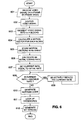
- FIG. 7 illustrates an exemplary flow diagram for selectively reducing a Huffman Coding rate for use in compressing a received digital signal.
- the digital signal includes a plurality of digital sets wherein ones of the digital sets are preferably non-unique.
- the exemplary process begins upon receipt of an electric signal representing the current coding rate, processing block 701.
- An array, or other suitable data structure or conventional storage device is preferably used to store each one of the plurality of digital sets once.
- Each digital set preferably represents a particular symbol, such as a motion vector in the illustrated embodiment, as previously discussed with reference to processing block 605 of FIG. 6.
- Each digital set preferably has an indictor associated therewith which represents the probability of occurrence, or frequency, of that symbol.
- Suitable conventional addressing and/or traversal techniques are preferably used to control and access the array.
- the current coding rate is compared with a threshold coding rate to determine whether the current coding rate satisfies a predetermined criteria, such as validity, processing block 702.
- a predetermined criteria such as validity, processing block 702.
- the threshold coding rate represents the maximum bandwidth. If the current coding rate does not satisfy the predetermined criteria, or is invalid, NO branch of decisional block 703, then ones of the digital sets are selectively discarded, processing block 704. Selectively discarded, as used herein, includes removing from consideration. In the illustrated embodiment, selected ones of the motion vectors are discarded to reduce the number of bits required to represent the remaining motion vectors. If the current motion vector coding rate is greater than the maximum rate (preferably a fixed code parameter, typically 15% of the total bits/video frame), the current coding rate is preferably reduced by discarding the motion vector(s) having the least prediction gain.
- Prediction gain, G PR may be defined as follows: Where B K,T is the current coding block in the current frame, B KT is the prediction of B K,T using a zero motion vector, and B ⁇ K,T is the coding block predicted using the actual motion vector.
- the prediction gain therefore is the improvement obtained from using a motion vector as opposed to assuming a zero motion vector.
- the motion vector having the least prediction gain is the motion vector for that block which provides the least improvement as compared to doing nothing at all (i.e., using a zero motion vector).
- the motion vector which yields the smallest G PR is accordingly discarded.
- particular symbols or individual occurrences or groups of occurrences of one or more symbols may be discarded. Further, the criteria for discarding a particular symbol, occurrence or group of occurrences of one or more symbols may be based upon a least prediction gain, as in the illustrated embodiment, or alternatively, upon a relatively low probability of occurrence or a metric based upon rate distortion, to name two examples.
- Re-computing the current Huffman Coding rate each time a symbol or an occurrence of a symbol is discarded is processing resource intensive. Further, the Huffman Coding rate, statistically, does not change substantially between iterations. The change in coding rate resulting from discarding a particular symbol, or one or more occurrences of a symbol, i.e., the difference between a new coding rate and the current coding rate is calculated, processing block 705.
- H 1 represents the entropy of the motion vectors before discarding one occurrence
- H 2 represents the entropy after discarding that occurrence
- the difference estimation is subtracted from the current Huffman Coding rate which yields the new Huffman Coding rate, processing block 706. If the new current coding rate is still greater than the threshold coding rate, processing block 702 and decisional block 703, then the foregoing process steps are preferably repeated until the current coding rate is valid.
- R M and N are both integral and have a finite range from 0 to 140.
- a look-up table of AlogA is preferably maintained, such as in the form of an array having 140 elements, for example. Alternatively, any other suitable data structure or conventional memory storage device may be utilized. ⁇ B may therefore be computed using four table look-ups and three additions.
- a preferred embodiment for using and/or distributing the present invention is software.
- the software embodiment may be implemented in any suitable programming language.
- a "C" programming language implementation for performing the aforementioned processing steps is attached herewith as an appendix.
Landscapes
- Engineering & Computer Science (AREA)
- Multimedia (AREA)
- Signal Processing (AREA)
- Compression Or Coding Systems Of Tv Signals (AREA)
- Compression, Expansion, Code Conversion, And Decoders (AREA)
Applications Claiming Priority (2)
| Application Number | Priority Date | Filing Date | Title |
|---|---|---|---|
| US400706 | 1995-03-08 | ||
| US08/400,706 US5872599A (en) | 1995-03-08 | 1995-03-08 | Method and apparatus for selectively discarding data when required in order to achieve a desired Huffman coding rate |
Publications (2)
| Publication Number | Publication Date |
|---|---|
| EP0731611A2 true EP0731611A2 (de) | 1996-09-11 |
| EP0731611A3 EP0731611A3 (de) | 1997-07-23 |
Family
ID=23584686
Family Applications (1)
| Application Number | Title | Priority Date | Filing Date |
|---|---|---|---|
| EP96301476A Withdrawn EP0731611A3 (de) | 1995-03-08 | 1996-03-05 | Gerät und Verfahren zur selektiven Verringerung einer Huffman-Kodierungsrate |
Country Status (4)
| Country | Link |
|---|---|
| US (1) | US5872599A (de) |
| EP (1) | EP0731611A3 (de) |
| JP (1) | JPH08279764A (de) |
| CA (1) | CA2170549A1 (de) |
Cited By (1)
| Publication number | Priority date | Publication date | Assignee | Title |
|---|---|---|---|---|
| US6831891B2 (en) * | 2001-03-06 | 2004-12-14 | Pluris, Inc. | System for fabric packet control |
Families Citing this family (7)
| Publication number | Priority date | Publication date | Assignee | Title |
|---|---|---|---|---|
| JP2000350136A (ja) * | 1999-03-26 | 2000-12-15 | Seiko Epson Corp | 画像データ処理システム |
| US6985633B2 (en) * | 2001-03-26 | 2006-01-10 | Ramot At Tel Aviv University Ltd. | Device and method for decoding class-based codewords |
| US7227998B2 (en) * | 2002-06-11 | 2007-06-05 | Canon Kabushiki Kaisha | Image processing apparatus, control method of the same, computer program, and computer-readable storage medium |
| US20060062478A1 (en) * | 2004-08-16 | 2006-03-23 | Grandeye, Ltd., | Region-sensitive compression of digital video |
| US20070064805A1 (en) * | 2005-09-16 | 2007-03-22 | Sony Corporation | Motion vector selection |
| CN102395984A (zh) * | 2009-04-14 | 2012-03-28 | 皇家飞利浦电子股份有限公司 | 用于视频内容分析的关键帧提取 |
| US11177823B2 (en) * | 2018-05-21 | 2021-11-16 | Google Llc | Data compression by local entropy encoding |
Family Cites Families (21)
| Publication number | Priority date | Publication date | Assignee | Title |
|---|---|---|---|---|
| US3701111A (en) * | 1971-02-08 | 1972-10-24 | Ibm | Method of and apparatus for decoding variable-length codes having length-indicating prefixes |
| US4302775A (en) * | 1978-12-15 | 1981-11-24 | Compression Labs, Inc. | Digital video compression system and methods utilizing scene adaptive coding with rate buffer feedback |
| US4385363A (en) * | 1978-12-15 | 1983-05-24 | Compression Labs, Inc. | Discrete cosine transformer |
| US4396906A (en) * | 1980-10-31 | 1983-08-02 | Sri International | Method and apparatus for digital Huffman encoding |
| US4541012A (en) * | 1982-01-04 | 1985-09-10 | Compression Labs, Inc. | Video bandwidth reduction system employing interframe block differencing and transform domain coding |
| US4646061A (en) * | 1985-03-13 | 1987-02-24 | Racal Data Communications Inc. | Data communication with modified Huffman coding |
| DE3678029D1 (de) * | 1985-04-17 | 1991-04-18 | Siemens Ag | Verfahren zur bilddatenreduktion fuer digitale fernsehsignale. |
| US4704628A (en) * | 1986-07-16 | 1987-11-03 | Compression Labs, Inc. | Combined intraframe and interframe transform coding system |
| US5079630A (en) * | 1987-10-05 | 1992-01-07 | Intel Corporation | Adaptive video compression system |
| EP0498578B1 (de) * | 1991-02-07 | 1999-04-07 | Canon Kabushiki Kaisha | Vorrichtung zum Kodieren von Bildern |
| JP3189861B2 (ja) * | 1992-11-13 | 2001-07-16 | ソニー株式会社 | 動画像符号化装置および方法 |
| US5172228A (en) * | 1991-11-19 | 1992-12-15 | Utah State University Foundation | Image compression method and apparatus employing distortion adaptive tree search vector quantization |
| JP2797159B2 (ja) * | 1992-03-02 | 1998-09-17 | カシオ計算機株式会社 | 画像データ圧縮装置及び画像データ圧縮方法 |
| US5541640A (en) * | 1992-06-23 | 1996-07-30 | Larson; Craig R. | Videophone for simultaneous audio and video communication via a standard telephone line |
| GB2274956B (en) * | 1993-02-05 | 1997-04-02 | Sony Broadcast & Communication | Image data compression |
| US5420639A (en) * | 1993-04-01 | 1995-05-30 | Scientific-Atlanta, Inc. | Rate adaptive huffman coding |
| US5389965A (en) * | 1993-04-01 | 1995-02-14 | At&T Corp. | Video telephone station having variable image clarity |
| US5550541A (en) * | 1994-04-01 | 1996-08-27 | Dolby Laboratories Licensing Corporation | Compact source coding tables for encoder/decoder system |
| US5541595A (en) * | 1994-05-19 | 1996-07-30 | Matsushita Electric Corporation Of America | Variable length code decoder for simultaneous decoding the most significant bits and the least significant bits of a variable length code |
| US5612747A (en) * | 1995-03-08 | 1997-03-18 | Lucent Technologies Inc. | Method and apparatus for vector quantization caching in a real time video coder |
| US5696563A (en) * | 1995-03-08 | 1997-12-09 | Lucent Technologies Inc. | Apparatus and methods for performing huffman coding |
-
1995
- 1995-03-08 US US08/400,706 patent/US5872599A/en not_active Expired - Lifetime
-
1996
- 1996-02-28 CA CA002170549A patent/CA2170549A1/en not_active Abandoned
- 1996-03-05 EP EP96301476A patent/EP0731611A3/de not_active Withdrawn
- 1996-03-08 JP JP8051948A patent/JPH08279764A/ja active Pending
Cited By (1)
| Publication number | Priority date | Publication date | Assignee | Title |
|---|---|---|---|---|
| US6831891B2 (en) * | 2001-03-06 | 2004-12-14 | Pluris, Inc. | System for fabric packet control |
Also Published As
| Publication number | Publication date |
|---|---|
| CA2170549A1 (en) | 1996-09-09 |
| JPH08279764A (ja) | 1996-10-22 |
| EP0731611A3 (de) | 1997-07-23 |
| US5872599A (en) | 1999-02-16 |
Similar Documents
| Publication | Publication Date | Title |
|---|---|---|
| US5764374A (en) | System and method for lossless image compression having improved sequential determination of golomb parameter | |
| US5835034A (en) | System and method for lossless image compression | |
| US7956774B2 (en) | Variable length coding method and variable length decoding method | |
| EP0734174B1 (de) | Verfahren zur adaptiver Komprimierung von digitalen Restbilddaten in einem DPCM-Kompressionssystem | |
| US4541012A (en) | Video bandwidth reduction system employing interframe block differencing and transform domain coding | |
| EP1653628B1 (de) | Verlustfreie adaptive Golomb/Rice Kodierung und Dekodierung von ganzzahligen Daten mit rückwärts-adaptiven Vorschriften. | |
| US5714950A (en) | System for variable-length-coding and variable-length-decoding digitaldata | |
| US20060092053A1 (en) | Lossless adaptive encoding and decoding of integer data | |
| US20060132334A1 (en) | Lossless adaptive encoding and decoding of integer data | |
| US8139635B2 (en) | Method for efficient encoding and decoding quantized sequence in Wyner-Ziv coding of video | |
| JPH09261078A (ja) | データ復号化方法及びその装置 | |
| US6188793B1 (en) | Encoding apparatus, decoding apparatus, encoding method and decoding method | |
| US5696563A (en) | Apparatus and methods for performing huffman coding | |
| US5872599A (en) | Method and apparatus for selectively discarding data when required in order to achieve a desired Huffman coding rate | |
| EP0659023B1 (de) | Verfahren und Vorrichtung zur Bilddatenkodierung und -kompression | |
| JP2000114974A (ja) | 符号化装置 | |
| US5850260A (en) | Methods and apparatus for determining a coding rate to transmit a set of symbols | |
| CN100568742C (zh) | 对图像内的对象按段数据进行编码及译码方法 | |
| US5293251A (en) | Encoding/decoding system with two-stages of encoding/decoding | |
| EP1473838A1 (de) | Verfahren zur Dekodierung von Kodes variabler Länge sowie entsprechender Empfänger | |
| Park et al. | Area efficient fast Huffman decoder for multimedia applications | |
| BC et al. | Q-Coder Bit Rate (MSB to LSB)(LSB to MSB) Plane BC GC BC GC BC GC | |
| Fowler Jr et al. | Design of a Real-Time Video-Compression System Using Differential Vector Quantization | |
| JP2000299640A (ja) | 適応確率推定方法、適応符号化方法、適応復号方法、適応確率推定装置、適応符号化装置及び適応復号装置 |
Legal Events
| Date | Code | Title | Description |
|---|---|---|---|
| PUAI | Public reference made under article 153(3) epc to a published international application that has entered the european phase |
Free format text: ORIGINAL CODE: 0009012 |
|
| AK | Designated contracting states |
Kind code of ref document: A2 Designated state(s): DE FR GB |
|
| RIN1 | Information on inventor provided before grant (corrected) |
Inventor name: ROSENBERG, JONATHAN DAVID |
|
| PUAL | Search report despatched |
Free format text: ORIGINAL CODE: 0009013 |
|
| AK | Designated contracting states |
Kind code of ref document: A3 Designated state(s): DE FR GB |
|
| STAA | Information on the status of an ep patent application or granted ep patent |
Free format text: STATUS: THE APPLICATION IS DEEMED TO BE WITHDRAWN |
|
| 18D | Application deemed to be withdrawn |
Effective date: 19980124 |
|
| P01 | Opt-out of the competence of the unified patent court (upc) registered |
Effective date: 20230520 |