EP0731965B1 - Sicherheit/schutzanlage mit sich darauf beziehender vorrichtung - Google Patents
Sicherheit/schutzanlage mit sich darauf beziehender vorrichtung Download PDFInfo
- Publication number
- EP0731965B1 EP0731965B1 EP95902380A EP95902380A EP0731965B1 EP 0731965 B1 EP0731965 B1 EP 0731965B1 EP 95902380 A EP95902380 A EP 95902380A EP 95902380 A EP95902380 A EP 95902380A EP 0731965 B1 EP0731965 B1 EP 0731965B1
- Authority
- EP
- European Patent Office
- Prior art keywords
- frequency
- microcomputer
- receiver
- over
- information
- Prior art date
- Legal status (The legal status is an assumption and is not a legal conclusion. Google has not performed a legal analysis and makes no representation as to the accuracy of the status listed.)
- Expired - Lifetime
Links
- 230000002265 prevention Effects 0.000 title abstract description 7
- 238000004891 communication Methods 0.000 claims description 41
- 230000005540 biological transmission Effects 0.000 claims description 19
- 238000000034 method Methods 0.000 claims description 8
- 230000006870 function Effects 0.000 abstract description 2
- 230000008859 change Effects 0.000 description 6
- 230000008054 signal transmission Effects 0.000 description 5
- 230000011664 signaling Effects 0.000 description 5
- 238000010586 diagram Methods 0.000 description 4
- 230000001133 acceleration Effects 0.000 description 3
- 230000033001 locomotion Effects 0.000 description 3
- 230000002452 interceptive effect Effects 0.000 description 2
- 230000004913 activation Effects 0.000 description 1
- 238000004458 analytical method Methods 0.000 description 1
- 238000013459 approach Methods 0.000 description 1
- 230000004888 barrier function Effects 0.000 description 1
- 230000008901 benefit Effects 0.000 description 1
- 230000002457 bidirectional effect Effects 0.000 description 1
- 230000004397 blinking Effects 0.000 description 1
- 238000007664 blowing Methods 0.000 description 1
- 238000004364 calculation method Methods 0.000 description 1
- 238000001514 detection method Methods 0.000 description 1
- 230000000694 effects Effects 0.000 description 1
- 238000005516 engineering process Methods 0.000 description 1
- 238000009434 installation Methods 0.000 description 1
- 238000012423 maintenance Methods 0.000 description 1
- 238000004519 manufacturing process Methods 0.000 description 1
- 238000012544 monitoring process Methods 0.000 description 1
- 230000003287 optical effect Effects 0.000 description 1
- 230000008447 perception Effects 0.000 description 1
- 230000008569 process Effects 0.000 description 1
- 238000012545 processing Methods 0.000 description 1
- 230000005236 sound signal Effects 0.000 description 1
- 230000001629 suppression Effects 0.000 description 1
- 238000012360 testing method Methods 0.000 description 1
- 230000007704 transition Effects 0.000 description 1
- 230000000007 visual effect Effects 0.000 description 1
Images


Classifications
-
- B—PERFORMING OPERATIONS; TRANSPORTING
- B60—VEHICLES IN GENERAL
- B60R—VEHICLES, VEHICLE FITTINGS, OR VEHICLE PARTS, NOT OTHERWISE PROVIDED FOR
- B60R25/00—Fittings or systems for preventing or indicating unauthorised use or theft of vehicles
- B60R25/10—Fittings or systems for preventing or indicating unauthorised use or theft of vehicles actuating a signalling device
- B60R25/102—Fittings or systems for preventing or indicating unauthorised use or theft of vehicles actuating a signalling device a signal being sent to a remote location, e.g. a radio signal being transmitted to a police station, a security company or the owner
-
- G—PHYSICS
- G08—SIGNALLING
- G08G—TRAFFIC CONTROL SYSTEMS
- G08G1/00—Traffic control systems for road vehicles
- G08G1/123—Traffic control systems for road vehicles indicating the position of vehicles, e.g. scheduled vehicles; Managing passenger vehicles circulating according to a fixed timetable, e.g. buses, trains, trams
- G08G1/127—Traffic control systems for road vehicles indicating the position of vehicles, e.g. scheduled vehicles; Managing passenger vehicles circulating according to a fixed timetable, e.g. buses, trains, trams to a central station ; Indicators in a central station
-
- G—PHYSICS
- G08—SIGNALLING
- G08G—TRAFFIC CONTROL SYSTEMS
- G08G1/00—Traffic control systems for road vehicles
- G08G1/16—Anti-collision systems
- G08G1/161—Decentralised systems, e.g. inter-vehicle communication
Definitions
- the base of the security/prevention system is an electronic device which has the capability of joining the performance of two functions, i.e. prevention of road accidents and theft protection of vehicles, using the principle of joint use of frequencies, whereby interference with the device's operation is prevented.
- the invention allows, on the one hand, such application in road traffic safety, in which an electronic security device installed in a vehicle provides passive and active warning of participants in the traffic as to momentary dangers requiring quick reaction of the driver.
- the device allows such application in road traffic safety, in which an electronic security device protects the vehicles against theft;
- the device comprises three base units, i.e. an electronic security device, which is installed in the vehicle and intended for transmitting messages about theft, a pocket receiver, and a network of receiver devices distributed at all locations of importance to the reception of the transmitted messages.
- the invention belongs to classes G01S 5/00, 5/02, 5/14, 3/50, G08G 1/01, 1/09, 1/16, 1/127, G08B 25/01, 25/10 of the International Patent Classification.
- the PCT document 92/06698 describes bidirectional exchange of data over radio (using one half-duplex frequency) between vehicles and fixed stations which make up a network and which are linked with a center. Interference suppression on the channel is carried out by means of a time-division multiplex and by spread centrum technology.
- the accent is on the methods of locating the position of a vehicle with respect to the receivers in the network.
- a device which comprises a transmitter and a receiver part linked into a system with sensors of collision and acceleration.
- the frequency of the transmitter and the receiver is not specified, and an aerial is provided which is oriented only in the driving direction.
- the system would be able to make out whether the vehicle approaches or moves away from the transmitter, on the basis of Doppler effect, or on the change of power of the received signal.
- the EP document No. 514 996 describes a system of theft protection of vehicles.
- the system would emit a code identifying the vehicle.
- Roadside receiver & coordination stations would receive the code and send it to a centre where the position of the vehicle could be calculated.
- the system operates at a frequency of 10-15 MHz and 10-15.6 GHz (communication with a satellite).
- the calculation of the position is made possible by means of the time delay between the signals received at different receiver stations. It also uses a gyroscope.
- the system comprises two parts, i.e. a part which is installed in vehicles and comprises three transmitters and a receiver, and a part which is installed in fixed control centres and has three receivers and a transmitter.
- the system is based on the principle that each of the three transmitters has its own frequency and a different power. This makes the first transmitter audible within a radius of 50 km, the second within a radius of 25 km, and the third within a radius of 1 km.
- a control system on a fixed frequency requests the transmission and gives the desired frequency. Depending on the frequency that "hears" it, it defines the distance and transmits the desired data to it.
- the device allows the transmission of RF signals which identify the actual state of a vehicle (e.g. sudden braking or acceleration, sudden stop as a result of crash, and similar), and the reception of signals containing important information on the actual state of other vehicles taking part in the traffic (e.g. accident, sudden braking, unexpected barriers).
- the device provides active or passive warning of participants in the traffic about direct hazards, giving the drivers more time for perception or reaction (prevents collisions or chain crashes on unsurveyable road sections or in bad weather conditions, clashes against broken down vehicles or unmarked vehicles.
- the device and/or system can also be used for calling attention to vehicles on an urgent ride.
- the latter should have their device equipped with additional software allowing manual switching of signalling in case of an urgent ride.
- the device can be used by road maintenance vehicles or slow vehicles, or by trains, which can use this device for signalling at unprotected level crossings. Also the sites of works on the road can be equipped with the device for better safety.
- a higher version of the device can also be used for automatic switching on and off the lights in tunnels or in bad weather conditions, or at poor visibility, for signalling at incorrect positioning of drivers on motorways.
- the device in the vehicle receives the information at which frequency it should receive or transmit signals or a digital code with which all the transmitted or received signal should be equipped, and which the device should then communicate to the driver. In this way the device in the car automatically selects the received signals and communicates only the relevant warnings to the driver.
- a more convenient way is that of changing frequencies, as this lowers the occupancy of the used frequency channel, which is heavily charged in the encoding system. Additional help is provided by the "weighting factor" of individual warning information, which defines the length of pause between individual transmitted information packages.
- weighting factor of individual warning information, which defines the length of pause between individual transmitted information packages.
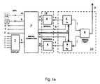
- the device consists of a microcomputer with an I/O module, a modem, a transceiver station, a digital speed sensor, and additionally also a power sensor, a display, a speaker, and an additional key for manual switch-on in the event of local danger on the road, as shown in Fig. 1.
- the microcomputer constantly updates or calculates momentary accelerations or deceleration of the vehicle.
- the sensor senses the drop of speed which brings about the decision to transmit an alarm signal.
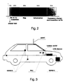
- Signals are transmitted in digital form in short information packages containing besides protocol symbols also information on the type of danger, as shown in Fig. 2.
- the device When there is no priority signal of collision of some other vehicle at the receiver station, the device starts transmitting in intervals over the modem by means of an RF transmitter, digital information packages on sudden braking of the vehicle. This happens independently of the driver, whose attention upon the transmission of his device is called by an acoustic signal or visibly, on his display.
- the transmission of a signal can be interrupted manually, if the driver considers it appropriate, or automatically, after a certain time delay.
- the RF receiver station in another car located in a radius of up to approximately 300 m communicates this package via modem to its own microcomputer. This reads the digital information and at the same time activates the acoustic signal and the related light symbol on the display.
- the received signal lasts as long as it is transmitted by the source, unless the driver interrupts it manually.
- the device operates in the mono mode on one or more own channels, otherwise it would not operate in case the channel were occupied by an undedicated user; in different countries, different channels may be used which are automatically adjusted at entering the country (throughout the country, and at border passing points, the roadside infrastructure should transmit information as to which channels the device should be tuned).
- the main parts of the device are a microcomputer 3, a modem 11, a high-frequency part 10 and periphery 1, 2 and 12.
- the microcomputer controls what is going on in the periphery (sensors) and, if necessary, activates the transmitter - sends a signal, and at the same time checks the receiving radio channel - should it happen to receive a signal from the device in some other vehicle.
- All possible states of sensors X, Y, Z - or more, are uniformly encoded in a digital code appropriate for transmission over a HF channel.
- the digital code is produced by the microcomputer 3 and communicated over communication d via the modulator 4 over communication e to the HF transmitter 6, and this sends the code in the useful part of the signal over communication i via the aerial part 8 or the aerial 9 into the air, allowing in this way the reception by other equivalent devices in other vehicles.
- the priority of the communicated information is provided in the device by means of adjustable time between two transmissions, and in order to prevent interference between the codes of the same priority a random delay is added to this time.
- the microcomputer in the period between two transmissions sense an optional signal from another device, it starts counting the time from the beginning, and does not transmit the code/signal. In this way it does not interfere with the codes/signals of a higher priority, while two codes of the same priority interchange the channel at random.
- the microcomputer may, over communication m, at any moment recognize the actual or at least the last measured absolute location of the vehicle, which in the event of crash allows it to transmit - after a certain time, if the transmission of signal is not manually interrupted - also the measured actual location of the vehicle.
- the microcomputer 3 processes the received digital codes/signals from other devices and communicates them to the driver over communication h by means of the periphery, i.e. the display 2 with outputs A, B,..., F.
- the invention comprises three base units, i.e. an electronic security device installed into the vehicle (possible installation is schematically illustrated in Fig. 3) and intended for transmitting messages on vehicle theft, a pocket receiver, and a network of receivers installed at all places important for the reception of transmitted messages.
- a schematic block diagram of the three basic units is shown in Fig. 4.
- Vehicles are fitted with an electronic device (which may be installed at a place unknown to the driver) which is, in the case of theft. autonomously and immediately activated and starts transmitting a specific digital RF signal containing the essential data of the vehicle - the make, the year of production and the colour, the registration number and the engine or chassis number.
- the alarm signal transmitter may also transmit the actual speed of the vehicle and even its actual coordinates (this is made possible by an incorporated GPS system).
- the average range of the alarm signal is within a radius of approximately 20 km.
- the receivers of these signals must be installed at appropriate locations along the road (an analysis has shown that the ideal locations are at petrol filling stations, at all border crossing points, and alongside motorways where emergency telephones are located), and on all higher mountain peaks where TV or telecommunication repeaters have been installed.
- the received alarm signals and their intensities are analyzed by the receivers and communicated to the data collecting centre where a special service sorts them by means of an expert computer system and establishes the location of the stolen vehicle, its direction of movement and speed. The centre then communicates these data to the police or some other security service.
- the described network is illustrated schematically in Fig. 5a and 5b.
- the alarm signal is captured by the pocket receiver that the owner should have on him (allowing him to inform the security service in the event of a false alarm, or to give the location of the vehicle at the time it got stolen).
- the pocket receiver is at the same time a HW/SW key by means of which the alarm can be switched off or the owner can identify himself to the device in his car, so that the alarm is not activated.
- FIG. 6 A flowchart of alarm communication is shown in Fig. 6.
- the described system has a certain resemblance with the U.S. "Tracker" system which is based on a similar physical principle.
- cars are equipped with a radio transmitter installed in a hidden place unknown to the driver.
- the owner alarms a service set up for this purpose by the police. From their centre the police activate, over strong transmitters, the radio transmitter in the stolen vehicle. Then they chase the RF signals from the stolen vehicle by their "chasing" receivers installed in the cars of said service within the police, and indirectly, also the stolen vehicle.
- An advantage of the device according to the invention against the "Tracker" system is that the former immediately activates the alarm independently of the owner, and this removes the first drawback and ensures immediate reaction of the police. This considerably increases the reliability of the system.
- the device can practically not be obstructed in transmitting the alarm signal, as it automatically uses only the free channels, while the interfered channels only mean "occupied" channels which the device cannot use at a given moment. Additional disabling of possible intentional interference of signal transmission is achieved by the mere fact that each subsequent information package is sent over a channel selected at random, which cannot be foreseen.
- Another feature of the system is that it can be used at sea, where the device is especially cost-effective in combination with a GPS.
- the system comprises devices installed in vehicles, pocket receivers and receiver stations.
- the transmitter device (a block diagram is shown in figure 1a) in the vehicles is mainly composed of a microcomputer 3, a modem 11, a HF part 10, communication k to a pocket receiver 1, sensors X, Y and X and possibly a GPS device 12.
- the microcomputer controls what is going on in the periphery (burglar detecting sensors) and, if necessary, activates the transmitter - sends a HF signal with an information package.
- the latter receives information on the changing of frequencies over the aerial 9 or the aerial part 8, so that, over communication j via the receiver 7, and then over communication f, a signal is received by the demodulator 5, which the demodulator 5 sends over communication g to the microcomputer 3. In this way the microcomputer 3 adjusts, via communication a, the working frequency or channel on the receiver 7 and transmitter 6.
- sensors X, Y and Z - or more - are uniformly defined, and in the event of burglary, they communicate electric signals to the microcomputer 3. All data about the vehicle are uniformly encoded in a digital code, and in the case of activation by the sensors, the microcomputer 3 transmits them over communication d via the modulator 4 over communication e to the HF transmitter 6, and this sends the code in the useful part of the signal over communication 1 via the aerial part 8 or the antenna 9 into the air, and thereby allows the nearest receiver devices to receive it.
- this over communication m provides to the microcomputer 3, at any moment, the information on the position of the vehicle in the space, in absolute coordinates. These coordinates are encoded by the microcomputer 3 and joined to the other useful data stored in the information package which the computer transmits into the air in the event of theft.
- the microcomputer In order to suppress interferences in cases of theft of several vehicles, all of which would transmit their information packages, the microcomputer would first select at random one of the permitted frequencies and transmit it over communication a to the receiving part 7 of the HF part 10 of the device and check whether the selected frequency or channel is free. If the the channel is unoccupied - the criterion of signal intensity or validity of digital code - the microcomputer 3 would tune over communication a the transmitting part 6 of the HF part to the selected channel, and over communication via the aerial part 8 or the aerial 9 transmit a certain number of digital information packages. Then, after a certain time, it would repeat the procedure. If the channel is busy, the procedure would be repeated, too - another random frequency would be selected and the occupancy of the channel would be checked. The selection of frequencies or channels would be carried out pseudo at random with the correlation that, in a certain time period, each frequency is selected at least once.
- the pocket receiver (Fig. 1c) can communicate with the base device installed in the vehicle with the assistance of the microcomputer 3 over communication a via the HW key 1, and can in this way identify itself or prevent the transmission of alarm signals.
- the microcomputer 3 may over communication by means of a beeper 2 give a sound signal to the vehicle owner that the device in the vehicle is transmitting an alarm signal. This is from the aerial 6 or the receiver 5 over communication via demodulator 4 over communication c recorded in the microcomputer 3 which can then adequately react.
- the receiver station in Fig. 1b comprises a microcomputer 3 connected over communication o to a telephone modem 2, a modem 11 and a HF part 10.
- the receiver device operates in such a way that the microcomputer 3 selects at random one of the permitted frequencies, on which could receive, over the HF part, information packages, and adjusts it over communication a on the receiver 6, then over the aerial 9 or the aerial part 8 over connection j via the receiver 7, over communication f via the demodulator 5 over communication d checks the channel's occupancy. When the channel is occupied by an analogue signal, the microcomputer selects another random channel and again checks its occupancy - the criterion of signal intensity or digital code validity.
- the computer starts processing the information received.
- the microcomputer 3 will change the receiving frequency to another random frequency of the HF part of the device.
- the receiver or the microcomputer will, after a certain period of time which is longer than or equal to the sum of transmission periods of the transmission device together on all permitted channels, change the receiving frequency of the HF part. This is an additional safety factor which prevents the interference of the receiver device.
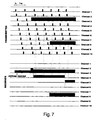
- a time diagram of frequency selecting and changing the carrier frequencies or channels is shown in Fig. 7, while a block diagram of decision making on operation of the device in various cases is shown in Fig. 8.
- This procedure ensures that the receiver station will not receive and wait for an alarm information package on a channel which is occupied by a "regular" user, prevents intentional interfering of the reception of an alarm information package, as an interfered channel or a group of interfered channels is simply skipped by the receiver device, and makes the receiving frequency practically unknown.
- this information is sent by the receiver device to the information collection centre.
- the microcomputer 3 in communication o by means of a telephone modem 2 via a telephone line sends its own identification data and the contents of the received information packages, or it can send them via an HF transmitter part over the air to another receiver station, which sends them by the same way to the next receiver station, or directly over telephone into the information collection centre.
- the centre can receive the data or the contents of individual information packages over a receiver station which is directly connected with the central computer, or via telephone lines over telephone modems.
- the received information is then processed by an expert system and sent to the service in charge of transmission.
- Another feature of the system is that it can be used at sea, where the device is especially cost-effective in combination with a GPS.
Landscapes
- Physics & Mathematics (AREA)
- General Physics & Mathematics (AREA)
- Engineering & Computer Science (AREA)
- Mechanical Engineering (AREA)
- Radar, Positioning & Navigation (AREA)
- Remote Sensing (AREA)
- Alarm Systems (AREA)
- Mobile Radio Communication Systems (AREA)
- Burglar Alarm Systems (AREA)
- Traffic Control Systems (AREA)
- Gas-Insulated Switchgears (AREA)
- Fittings On The Vehicle Exterior For Carrying Loads, And Devices For Holding Or Mounting Articles (AREA)
- Emergency Alarm Devices (AREA)
Claims (4)
- Straßenverkehrssicherheits- und/oder Diebstahlsschutzvorrichtung für Fahrzeuge mit einer im Fahrzeug eingebauten Grundvorrichtung, worin die Grundvorrichtung einen Hochfrequenzteil (10), einen Sender (6), einen Empfänger (7) und zumindest einen Informationseingang aufweist, wobei die Vorrichtung mit Übertragungssignalen kleiner Leistung arbeitet und die Verschlüsselung oder Auswahl der empfangenen Signale mittels spezifischem Code oder Sender spezifischer Frequenz der Straßeninfrastruktur einsetzt, so daß das Fahrzeug auf einzelnen Straßenabschnitten die Information empfängt, auf welcher Frequenz es Alarmsignale empfangen oder übertragen sollte oder den digitalen Code, mit welchem die übertragenen oder die empfangenen von der Vorrichtung verarbeiteten Signale ausgestattet sind,
dadurch gekennzeichnet, daß
zur Verhinderung von Störungen ein Mikrocomputer (3), um Daten zu übermitteln,der Mikrocomputer (3), um Daten zu empfangen,a) zufällig eine von mehreren in dem Straßenabschnitt zugelassenen Frequenzen des Hochfrequenzteils (10) auswählt und den Empfänger (7) über einen Übermittlungspfad (a) auf die ausgewählte Frequenz einstellt; dann der durch einen Signalpfad (f, g) mit dem Empfänger (7) verbundene Mikrocomputer (3) überprüft, ob die ausgewählte Frequenz frei ist;b) wenn die ausgewählte Frequenz frei ist, der Mikrocomputer (3) über einen Übermittlungspfad (a) den Sender (6) auf die ausgewählte Frequenz einstellt und über einen Übermittlungspfad (d) über einen Sender-Signalumsetzer (4), einen Antennenteil (8) und eine Antenne (9) eine bestimmte Anzahl von digitalen, kodierten Informationspaketen überträgt und die Schritte a) bis c) nach einer gewissen Zeitdauer wiederholt;c) wenn die ausgewählte Frequenz besetzt ist, der Mikrocomputer (3) die Empfangsfrequenz wiederum zufällig auf eine andere in dem Straßenabschnitt erlaubte Frequenz des Hochfrequenzteils (10) wechselt und mit dem Schritt b) fortsetzt;d) zufällig eine von mehreren in dem Straßenabschnitt zugelassenen Frequenzen des Hochfrequenzteils (10) auswählt und über einen Übermittlungspfad (a) an den Empfänger (7) sendet; dann der durch einen Signalpfad (f, g) mit dem Empfänger (7) verbundene Mikrocomputer (3) überprüft, ob die ausgewählte Frequenz frei ist;e) in dem Fall, daß die ausgewählte Frequenz durch ein Signal gültigen Codes besetzt ist, welches zu einer bestimmten Zeit den spezifischen Code von Informationspaketen beinhaltet, die empfangene Information verarbeitet wird; daß trotz der Tatsache, daß die Grundvorrichtung erfolgreiche Informationspakete auf einer bestimmten Frequenz empfängt, die Empfangsfrequenz auf eine andere erlaubte Frequenz nach einer bestimmten Zeit, welche länger oder gleich der Summe von Übertragungsperioden der Übertragungsvorrichtung auf allen zugelassenen Frequenzen ist, geändert wird;f) wenn nach einer bestimmten Zeit der Mikrocomputer (3) den spezifischen Code nicht erkennt oder wenn ein Analogsignal auf der ausgewählten Frequenz auftritt, der Mikrocomputer (3) wiederum zufällig die Empfangsfrequenz auf eine andere im Straßenabschnitt erlaubte Frequenz des Hochfrequenzteils (10) ändert und mit Schritt e) fortfährt. - Straßenverkehrssicherheits- und/oder Diebstahlsschutzvorrichtung nach Anspruch 1,
dadurch gekennzeichnet, daß
ein Gewichtungsfaktor zu den einzelnen Stücken von Alarminformationen hinzugefügt wird, welcher die Länge der Pause zwischen einzelnen Informationspaketen festlegt. - Straßenverkehrssicherheits- und/oder Diebstahlsschutzvorrichtung nach Anspruch 1 oder 2,
dadurch gekennzeichnet, daß
sie eine Empfangsvorrichtung aufweist, umfassend einen über einen Übermittlungspfad (o) mit einem Telephonmodem (16) verbundenen Mikrocomputer (3), ein Modem (11) und Hochfrequenzteil (10),a) wobei der Mikrocomputer (3) zufällig eine der auf dem Straßenabschnitt zugelassenen Frequenzen des Hochfrequenzteils (10) auswählt und einen Empfänger (7) über einen Übermittlungspfad (a) auf die ausgewählte Frequenz einstellt; dann der durch einen Signalpfad (f, g) mit dem Empfänger (7) verbundenen Mikrocomputer (3) überprüft, ob die ausgewählte Frequenz frei ist;b) in dem Fall, daß die ausgewählte Frequenz durch ein Signal gültigen Codes besetzt ist, welches zu einer bestimmten Zeit den spezifischen Code von Informationspaketen beinhaltet, die empfangene Information verarbeitet wird; daß trotz der Tatsache, daß die Grundvorrichtung erfolgreiche Informationspakete auf einer bestimmten Frequenz empfängt, die Empfangsfrequenz auf eine andere erlaubte Frequenz geändert wird nach einer bestimmten Zeit, welche länger oder gleich der Summe von Übertragungsperioden der Grundvorrichtung auf allen zugelassenen Frequenzen ist, wodurch der Zeitvorgang des Auswählens und Wechselns der Trägerfrequenzen festgelegt wird;c) wenn nach einer bestimmten Zeit der Mikrocomputer (3) den spezifischen Code nicht erkennt oder wenn ein Analogsignal auf der ausgewählten Frequenz auftritt, der Mikrocomputer (3) wiederum zufällig die Empfangsfrequenz auf eine andere im Straßenabschnitt erlaubte Frequenz des Hochfrequenzteils (10) wechselt und mit Schritt b) fortfährt. - Straßenverkehrssicherheits- und/oder Diebstahlsschutzvorrichtung nach jedem der Ansprüche 1 bis 3,
dadurch gekennzeichnet, daß
ein Taschenempfänger (1), unterstützt von einem Mikrocomputer (3) über Übermittlungspfad (a) mittels eines Tasters (13) mit der im Fahrzeug eingebauten Grundvorrichtung in Verbindung treten kann, während der Mikrocomputer (3) über einen Übermittlungspfad (q) mittels eines Piepsers (14) den Eigentümer eines Alarmsignals warnt, welches im Mikrocomputer (3) über eine Antenne (6 - Fig. 1c) zu einem Empfänger (5 - Fig. 1c) über einen Übermittlungspfad (r) durch den Empfänger-Signalumsetzer (4 - Fig. 1c) hindurch aufgezeichnet wird.
Applications Claiming Priority (3)
| Application Number | Priority Date | Filing Date | Title |
|---|---|---|---|
| SI9300634A SI9300634A (en) | 1993-12-03 | 1993-12-03 | Safety preventive method and coresponding device |
| SI9300634 | 1993-12-03 | ||
| PCT/SI1994/000019 WO1995015546A2 (en) | 1993-12-03 | 1994-12-02 | Security/prevention system with related device |
Publications (2)
| Publication Number | Publication Date |
|---|---|
| EP0731965A1 EP0731965A1 (de) | 1996-09-18 |
| EP0731965B1 true EP0731965B1 (de) | 1998-09-16 |
Family
ID=20431290
Family Applications (1)
| Application Number | Title | Priority Date | Filing Date |
|---|---|---|---|
| EP95902380A Expired - Lifetime EP0731965B1 (de) | 1993-12-03 | 1994-12-02 | Sicherheit/schutzanlage mit sich darauf beziehender vorrichtung |
Country Status (14)
| Country | Link |
|---|---|
| US (1) | US5900814A (de) |
| EP (1) | EP0731965B1 (de) |
| JP (1) | JPH09505919A (de) |
| AT (1) | ATE171294T1 (de) |
| AU (1) | AU1126595A (de) |
| CA (1) | CA2177369A1 (de) |
| CZ (1) | CZ155196A3 (de) |
| DE (1) | DE69413416T2 (de) |
| ES (1) | ES2122519T3 (de) |
| HU (1) | HUT76214A (de) |
| PL (1) | PL314869A1 (de) |
| SI (1) | SI9300634A (de) |
| SK (1) | SK68696A3 (de) |
| WO (1) | WO1995015546A2 (de) |
Families Citing this family (10)
| Publication number | Priority date | Publication date | Assignee | Title |
|---|---|---|---|---|
| DE19607375A1 (de) * | 1996-02-27 | 1997-08-28 | Detex Deutsche Textfunk Gmbh | Verfahren und Einrichtung zum Wiederauffinden von Fahrzeugen |
| US6009355A (en) * | 1997-01-28 | 1999-12-28 | American Calcar Inc. | Multimedia information and control system for automobiles |
| WO2000028410A1 (en) * | 1998-11-06 | 2000-05-18 | Phoenix Group, Inc. | Mobile vehicle accident data system |
| AUPQ117099A0 (en) * | 1999-06-23 | 1999-07-15 | Commonwealth Scientific And Industrial Research Organisation | A collison avoidance system |
| US6759942B2 (en) * | 2001-10-08 | 2004-07-06 | Ford Global Technologies, Llc | Vehicle communication system implemented reusing existing vehicle components |
| CZ297511B6 (cs) * | 2005-07-04 | 2007-01-03 | MĂĽller@Jan | Systém zabezpečení přemístitelných předmětů fixací jejich polohy |
| US20100185411A1 (en) * | 2009-01-16 | 2010-07-22 | Randall Richard Pfeiffer | Object monitor |
| US8717181B2 (en) | 2010-07-29 | 2014-05-06 | Hill-Rom Services, Inc. | Bed exit alert silence with automatic re-enable |
| CN104828014A (zh) | 2015-05-28 | 2015-08-12 | 京东方科技集团股份有限公司 | 一种车辆安全驾驶的方法、装置和系统 |
| SE541069C2 (en) * | 2015-10-09 | 2019-03-26 | Nida Tech Sweden Ab | Vehicle alarm system with multiple devices |
Family Cites Families (7)
| Publication number | Priority date | Publication date | Assignee | Title |
|---|---|---|---|---|
| DE2329870C3 (de) * | 1970-06-13 | 1982-07-22 | Klöckner, Karl, 5238 Hachenburg | Automatische Gefahrenwarneinrichtung mit Unfallschalter und mit automatischer bzw. manueller Empfangsmodulationsfrequenzumschaltung |
| FR2420174A1 (fr) * | 1978-03-15 | 1979-10-12 | Dassault Electronique | Installation pour la protection des personnes et des biens dans une agglomeration urbaine |
| JPS59186436A (ja) * | 1983-04-07 | 1984-10-23 | Sony Corp | コ−ドレステレホン |
| US4740792A (en) * | 1986-08-27 | 1988-04-26 | Hughes Aircraft Company | Vehicle location system |
| JP2666454B2 (ja) * | 1989-01-24 | 1997-10-22 | 富士通株式会社 | 無線自動警報転送方式 |
| US5293163A (en) * | 1990-06-06 | 1994-03-08 | Mazda Motor Corporation | Navigation apparatus for vehicles |
| FR2682792B1 (fr) * | 1991-10-16 | 1995-10-20 | Ii Bc Sys | Dispositif destine a eviter les carambolages en chaine. |
-
1993
- 1993-12-03 SI SI9300634A patent/SI9300634A/sl unknown
-
1994
- 1994-12-02 DE DE69413416T patent/DE69413416T2/de not_active Expired - Fee Related
- 1994-12-02 HU HU9601473A patent/HUT76214A/hu unknown
- 1994-12-02 CA CA002177369A patent/CA2177369A1/en not_active Abandoned
- 1994-12-02 ES ES95902380T patent/ES2122519T3/es not_active Expired - Lifetime
- 1994-12-02 US US08/647,967 patent/US5900814A/en not_active Expired - Fee Related
- 1994-12-02 CZ CZ961551A patent/CZ155196A3/cs unknown
- 1994-12-02 AU AU11265/95A patent/AU1126595A/en not_active Abandoned
- 1994-12-02 JP JP7515565A patent/JPH09505919A/ja active Pending
- 1994-12-02 PL PL94314869A patent/PL314869A1/xx unknown
- 1994-12-02 AT AT95902380T patent/ATE171294T1/de not_active IP Right Cessation
- 1994-12-02 WO PCT/SI1994/000019 patent/WO1995015546A2/en not_active Ceased
- 1994-12-02 SK SK686-96A patent/SK68696A3/sk unknown
- 1994-12-02 EP EP95902380A patent/EP0731965B1/de not_active Expired - Lifetime
Also Published As
| Publication number | Publication date |
|---|---|
| EP0731965A1 (de) | 1996-09-18 |
| ATE171294T1 (de) | 1998-10-15 |
| HUT76214A (en) | 1997-07-28 |
| PL314869A1 (en) | 1996-09-30 |
| US5900814A (en) | 1999-05-04 |
| WO1995015546A3 (en) | 1995-07-06 |
| SK68696A3 (en) | 1998-03-04 |
| DE69413416T2 (de) | 2000-05-11 |
| WO1995015546A2 (en) | 1995-06-08 |
| HU9601473D0 (en) | 1996-07-29 |
| ES2122519T3 (es) | 1998-12-16 |
| DE69413416D1 (de) | 1998-10-22 |
| CZ155196A3 (en) | 1997-02-12 |
| SI9300634A (en) | 1995-06-30 |
| CA2177369A1 (en) | 1995-06-08 |
| JPH09505919A (ja) | 1997-06-10 |
| AU1126595A (en) | 1995-06-19 |
Similar Documents
| Publication | Publication Date | Title |
|---|---|---|
| USRE38763E1 (en) | Emergency vehicle warning system and method | |
| US5289182A (en) | Electronic anti-collison device carried on board a vehicle | |
| USRE47408E1 (en) | Systems and/or methods of data acquisition from a transceiver | |
| CN101896953B (zh) | 经由移动通信的车辆的车辆相关数据传输 | |
| US6615137B2 (en) | Method and apparatus for transferring information between vehicles | |
| JP4321068B2 (ja) | 車両・歩行者間無線通信システム | |
| US20090189754A1 (en) | Vehicle impact warning device | |
| JP3999363B2 (ja) | 交通情報を形成する方法および車両用テレマティーク装置 | |
| KR100831935B1 (ko) | 적응형 통신 기술을 이용한 지능형 차량 안전 운행 방법 및시스템 | |
| US9232406B2 (en) | Systems and/or methods of data acquisition from a transceiver | |
| EP0731965B1 (de) | Sicherheit/schutzanlage mit sich darauf beziehender vorrichtung | |
| JP4930531B2 (ja) | 車載無線通信装置及び歩行者携帯無線通信装置 | |
| KR20060056370A (ko) | 이동 경로를 따른 물품들의 이동성을 판정하는 방법 및시스템 | |
| JP4924637B2 (ja) | 車両・歩行者間無線通信システム、車載無線通信装置及び歩行者携帯無線通信装置 | |
| JPH05508948A (ja) | 道路事故防止用警告システム | |
| GB2300996A (en) | Emergency communications system for use in a vehicle | |
| EP0510131B1 (de) | Elektronische vorrichtung zur vermeidung von zusammenstössen zwischen fahrzeugen | |
| WO1993016453A1 (en) | Road accident warning system | |
| USRE49644E1 (en) | Systems and/or methods of data acquisition from a transceiver | |
| US4117404A (en) | System of communications to alert police personnel of trouble on expressways | |
| KR100835804B1 (ko) | 자동차 2차 사고 예방을 위한 무선 송수신 장치 | |
| EP1953727A1 (de) | System zur selektiven Notfallsignalisierung zwischen Fahrzeugen zur Vermeidung falscher Alarme | |
| AU2024228171A1 (en) | Optimized device for signaling road emergencies | |
| HK1123117A (en) | System for selective emergency signalling between vehicles suitable for avoiding false alarms | |
| KR19990030773A (ko) | 공중파를 이용한 도난 차량 경보 장치 및 방법 |
Legal Events
| Date | Code | Title | Description |
|---|---|---|---|
| PUAI | Public reference made under article 153(3) epc to a published international application that has entered the european phase |
Free format text: ORIGINAL CODE: 0009012 |
|
| 17P | Request for examination filed |
Effective date: 19960612 |
|
| AK | Designated contracting states |
Kind code of ref document: A1 Designated state(s): AT BE CH DE DK ES FR GB GR IE IT LI NL PT SE |
|
| 17Q | First examination report despatched |
Effective date: 19970221 |
|
| GRAG | Despatch of communication of intention to grant |
Free format text: ORIGINAL CODE: EPIDOS AGRA |
|
| GRAG | Despatch of communication of intention to grant |
Free format text: ORIGINAL CODE: EPIDOS AGRA |
|
| GRAH | Despatch of communication of intention to grant a patent |
Free format text: ORIGINAL CODE: EPIDOS IGRA |
|
| GRAH | Despatch of communication of intention to grant a patent |
Free format text: ORIGINAL CODE: EPIDOS IGRA |
|
| GRAA | (expected) grant |
Free format text: ORIGINAL CODE: 0009210 |
|
| AK | Designated contracting states |
Kind code of ref document: B1 Designated state(s): AT BE CH DE DK ES FR GB GR IE IT LI NL PT SE |
|
| PG25 | Lapsed in a contracting state [announced via postgrant information from national office to epo] |
Ref country code: NL Free format text: LAPSE BECAUSE OF FAILURE TO SUBMIT A TRANSLATION OF THE DESCRIPTION OR TO PAY THE FEE WITHIN THE PRESCRIBED TIME-LIMIT Effective date: 19980916 Ref country code: LI Free format text: LAPSE BECAUSE OF FAILURE TO SUBMIT A TRANSLATION OF THE DESCRIPTION OR TO PAY THE FEE WITHIN THE PRESCRIBED TIME-LIMIT Effective date: 19980916 Ref country code: GR Free format text: LAPSE BECAUSE OF NON-PAYMENT OF DUE FEES Effective date: 19980916 Ref country code: CH Free format text: LAPSE BECAUSE OF FAILURE TO SUBMIT A TRANSLATION OF THE DESCRIPTION OR TO PAY THE FEE WITHIN THE PRESCRIBED TIME-LIMIT Effective date: 19980916 Ref country code: BE Free format text: LAPSE BECAUSE OF FAILURE TO SUBMIT A TRANSLATION OF THE DESCRIPTION OR TO PAY THE FEE WITHIN THE PRESCRIBED TIME-LIMIT Effective date: 19980916 Ref country code: AT Free format text: LAPSE BECAUSE OF FAILURE TO SUBMIT A TRANSLATION OF THE DESCRIPTION OR TO PAY THE FEE WITHIN THE PRESCRIBED TIME-LIMIT Effective date: 19980916 |
|
| REF | Corresponds to: |
Ref document number: 171294 Country of ref document: AT Date of ref document: 19981015 Kind code of ref document: T |
|
| REG | Reference to a national code |
Ref country code: CH Ref legal event code: EP |
|
| REF | Corresponds to: |
Ref document number: 69413416 Country of ref document: DE Date of ref document: 19981022 |
|
| PGFP | Annual fee paid to national office [announced via postgrant information from national office to epo] |
Ref country code: FR Payment date: 19981110 Year of fee payment: 5 |
|
| ET | Fr: translation filed | ||
| PGFP | Annual fee paid to national office [announced via postgrant information from national office to epo] |
Ref country code: DE Payment date: 19981124 Year of fee payment: 5 |
|
| PGFP | Annual fee paid to national office [announced via postgrant information from national office to epo] |
Ref country code: GB Payment date: 19981127 Year of fee payment: 5 |
|
| PG25 | Lapsed in a contracting state [announced via postgrant information from national office to epo] |
Ref country code: IE Free format text: LAPSE BECAUSE OF NON-PAYMENT OF DUE FEES Effective date: 19981202 |
|
| REG | Reference to a national code |
Ref country code: IE Ref legal event code: FG4D |
|
| PG25 | Lapsed in a contracting state [announced via postgrant information from national office to epo] |
Ref country code: SE Free format text: LAPSE BECAUSE OF FAILURE TO SUBMIT A TRANSLATION OF THE DESCRIPTION OR TO PAY THE FEE WITHIN THE PRESCRIBED TIME-LIMIT Effective date: 19981216 Ref country code: DK Free format text: LAPSE BECAUSE OF FAILURE TO SUBMIT A TRANSLATION OF THE DESCRIPTION OR TO PAY THE FEE WITHIN THE PRESCRIBED TIME-LIMIT Effective date: 19981216 |
|
| REG | Reference to a national code |
Ref country code: ES Ref legal event code: FG2A Ref document number: 2122519 Country of ref document: ES Kind code of ref document: T3 |
|
| PG25 | Lapsed in a contracting state [announced via postgrant information from national office to epo] |
Ref country code: PT Free format text: LAPSE BECAUSE OF FAILURE TO SUBMIT A TRANSLATION OF THE DESCRIPTION OR TO PAY THE FEE WITHIN THE PRESCRIBED TIME-LIMIT Effective date: 19981218 |
|
| PGFP | Annual fee paid to national office [announced via postgrant information from national office to epo] |
Ref country code: ES Payment date: 19981224 Year of fee payment: 5 |
|
| NLV1 | Nl: lapsed or annulled due to failure to fulfill the requirements of art. 29p and 29m of the patents act | ||
| REG | Reference to a national code |
Ref country code: CH Ref legal event code: PL |
|
| PLBE | No opposition filed within time limit |
Free format text: ORIGINAL CODE: 0009261 |
|
| STAA | Information on the status of an ep patent application or granted ep patent |
Free format text: STATUS: NO OPPOSITION FILED WITHIN TIME LIMIT |
|
| 26N | No opposition filed | ||
| REG | Reference to a national code |
Ref country code: IE Ref legal event code: MM4A |
|
| PG25 | Lapsed in a contracting state [announced via postgrant information from national office to epo] |
Ref country code: GB Free format text: LAPSE BECAUSE OF NON-PAYMENT OF DUE FEES Effective date: 19991202 |
|
| GBPC | Gb: european patent ceased through non-payment of renewal fee |
Effective date: 19991202 |
|
| PG25 | Lapsed in a contracting state [announced via postgrant information from national office to epo] |
Ref country code: FR Free format text: LAPSE BECAUSE OF NON-PAYMENT OF DUE FEES Effective date: 20000831 |
|
| PG25 | Lapsed in a contracting state [announced via postgrant information from national office to epo] |
Ref country code: DE Free format text: LAPSE BECAUSE OF NON-PAYMENT OF DUE FEES Effective date: 20001003 |
|
| REG | Reference to a national code |
Ref country code: FR Ref legal event code: ST |
|
| PG25 | Lapsed in a contracting state [announced via postgrant information from national office to epo] |
Ref country code: ES Free format text: LAPSE BECAUSE OF NON-PAYMENT OF DUE FEES Effective date: 20001203 |
|
| REG | Reference to a national code |
Ref country code: ES Ref legal event code: FD2A Effective date: 20010113 |
|
| PG25 | Lapsed in a contracting state [announced via postgrant information from national office to epo] |
Ref country code: IT Free format text: LAPSE BECAUSE OF NON-PAYMENT OF DUE FEES Effective date: 20051202 |