EP0732010B1 - Appareil radio - Google Patents
Appareil radio Download PDFInfo
- Publication number
- EP0732010B1 EP0732010B1 EP95901339A EP95901339A EP0732010B1 EP 0732010 B1 EP0732010 B1 EP 0732010B1 EP 95901339 A EP95901339 A EP 95901339A EP 95901339 A EP95901339 A EP 95901339A EP 0732010 B1 EP0732010 B1 EP 0732010B1
- Authority
- EP
- European Patent Office
- Prior art keywords
- frequency
- mhz
- controllable oscillator
- oscillator
- radio device
- Prior art date
- Legal status (The legal status is an assumption and is not a legal conclusion. Google has not performed a legal analysis and makes no representation as to the accuracy of the status listed.)
- Expired - Lifetime
Links
- 230000005540 biological transmission Effects 0.000 claims description 14
- 238000009529 body temperature measurement Methods 0.000 claims description 3
- 230000015572 biosynthetic process Effects 0.000 claims 1
- 239000000969 carrier Substances 0.000 claims 1
- 238000010586 diagram Methods 0.000 description 2
- 230000003321 amplification Effects 0.000 description 1
- QABCGOSYZHCPGN-UHFFFAOYSA-N chloro(dimethyl)silicon Chemical compound C[Si](C)Cl QABCGOSYZHCPGN-UHFFFAOYSA-N 0.000 description 1
- 230000008878 coupling Effects 0.000 description 1
- 238000010168 coupling process Methods 0.000 description 1
- 238000005859 coupling reaction Methods 0.000 description 1
- 239000000203 mixture Substances 0.000 description 1
- 238000003199 nucleic acid amplification method Methods 0.000 description 1
Images

Classifications
-
- H—ELECTRICITY
- H04—ELECTRIC COMMUNICATION TECHNIQUE
- H04B—TRANSMISSION
- H04B1/00—Details of transmission systems, not covered by a single one of groups H04B3/00 - H04B13/00; Details of transmission systems not characterised by the medium used for transmission
- H04B1/005—Details of transmission systems, not covered by a single one of groups H04B3/00 - H04B13/00; Details of transmission systems not characterised by the medium used for transmission adapting radio receivers, transmitters andtransceivers for operation on two or more bands, i.e. frequency ranges
-
- H—ELECTRICITY
- H04—ELECTRIC COMMUNICATION TECHNIQUE
- H04B—TRANSMISSION
- H04B1/00—Details of transmission systems, not covered by a single one of groups H04B3/00 - H04B13/00; Details of transmission systems not characterised by the medium used for transmission
- H04B1/38—Transceivers, i.e. devices in which transmitter and receiver form a structural unit and in which at least one part is used for functions of transmitting and receiving
- H04B1/40—Circuits
- H04B1/403—Circuits using the same oscillator for generating both the transmitter frequency and the receiver local oscillator frequency
- H04B1/406—Circuits using the same oscillator for generating both the transmitter frequency and the receiver local oscillator frequency with more than one transmission mode, e.g. analog and digital modes
Definitions
- the invention relates to a radio device according to the preamble of the main claim.
- Document EP-A-541 305 (Nokia Mobile Phones, May 12, 1993) discloses a radio containing a first oscillator and a second oscillator.
- the frequencies of the oscillators are selected so that a difference in frequencies gives a transmission frequency in a lower frequency range and a sum of frequencies gives a transmission frequency in an upper frequency range.
- the two oscillators are coupled via frequency dividers with a reference oscillator.
- Object of the present invention is to design the frequency and clock processing in a radio with the lowest possible number of components such that for different frequency ranges, in particular those of the GSM standard and the DMCS-1800 standards, the most important components, such as Oscillators or filters are largely identical.
- the radio according to the invention has the advantage that the same oscillators and associated circuits can be used for both frequency ranges.
- a development of the radio device according to the invention is that for receiving an intermediate frequency is formed as the difference between the frequency of the received signal and the frequency of the second controllable oscillator. As a result, the use of the same selection means is also possible in the receiving part.
- a further intermediate frequency is generated.
- the signal is quadrature demodulated with the further intermediate frequency, wherein a required for Quadraturdemodulation reference carrier is generated by a third controllable oscillator, which is coupled to the first controllable oscillator.
- the second controllable oscillator with the aid of a phase comparison circuit is controllable, which divided by a first frequency divider with respect to the frequency output of the first controllable oscillator and divided by a second frequency divider with respect to the frequency output of the second controllable oscillator can be fed.
- the divider ratio of the second frequency divider is controllable.
- the frequency-divided signals which can be supplied to the phase-comparator circuit have a frequency corresponding to the channel pitch.
- the second controllable oscillator can be used both for transmitting and for receiving.
- the frequency required in the respective time slot for transmission and reception is then set by a corresponding setting of the frequency divider by the microprocessor.
- a second controllable oscillator may be provided, each with a phase comparison circuit and a respective second frequency divider.
- An advantageous embodiment of the invention is that for controlling the frequency of the first controllable oscillator, a microprocessor generates a control signal for the first controllable oscillator by comparison between the system clock of the received signal and the system reference frequency and by temperature measurement, which can be supplied via a digital / analog converter to the first controllable oscillator. For an excellent stability of the frequency of the first controllable oscillator can be achieved.
- the frequency of the first controllable oscillator is an integer multiple of 13 MHz, preferably 33 times.
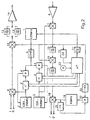
- a first controllable oscillator 1 which operates at a fixed frequency of 429 MHz. This is 33 times 13 MHz, which is the system clock set in the GSM standard.
- a second controllable oscillator 2 is tunable in the range of 1281 MHz to 1434 MHz in steps of 200 kHz each.
- the oscillator 2 is coupled via an adjustable frequency divider 3, a phase comparison circuit 4 and a fixed frequency divider 5 to the oscillator 1 and provides a carrier signal for a modulator 6, the modulation signals I and Q are fed in a conventional manner, in the transmitting part and for a mixer 7, which receives via an amplifier 8, the signals received from an antenna, not shown, in the receiving part.
- the divider ratio n of the frequency divider 3 can be set between 6405 and 7170 by means of a microprocessor 9. Due to the division of the frequency of the oscillator 1 at 5, the phase comparison is carried out at 4 with signals whose frequency is 200 kHz. As a result, an incrementation of the divider factor n in each case means a frequency jump of 200 kHz.
- a coupling of the output signal of the oscillator 1 with the system clock contained in the received signals is carried out with the aid of the microprocessor 9, to which the output signal of the oscillator 1 via a frequency divider 10 is supplied and a control signal via a digital / analog converter 11 to the oscillator 1 passes ,
- the microprocessor 9 receives in radio devices of the type in question in a conventional manner, the demodulated received signals, from which it derives the system clock for the purpose of comparison with the frequency generated by the frequency divider 10 system reference frequency.
- an intermediate frequency of 474 kHz is filtered out on the receiving side from the mixed product with the aid of a bandpass filter 15, which is then mixed at 16 with the frequency of the oscillator 1.
- the mixed product is passed through a bandpass filter 17, so that forms a second intermediate frequency of 45 MHz.
- This is demodulated in a quadrature demodulator 18, to which the signals I 'and Q' can be taken.
- a required for the quadrature demodulator 18 carrier also 45 MHz is generated with a third controllable oscillator 19 which is coupled by means of a phase comparison circuit 20 and two frequency dividers 21, 22 to the oscillator 1.
- a temperature compensation can be included, wherein the microprocessor based on a temperature measurement via a sensor 23, the control signal influenced in an appropriate manner.
- the oscillator 2 is switched between the frequencies required for transmission and reception respectively. This is possible because in the systems in question (for example GSM standard), the time slots for transmission and reception are shifted in time relative to one another.
- FIG. 2 corresponds to that of FIG. 1.
- the invention is not limited to the frequencies specified in the exemplary embodiment.
- other multiples of 13 MHz than 33 may be generated in oscillator 1 - for example, 416 MHz, 390 MHz or 351 MHz.
- For the second intermediate frequency values of 71 MHz, 90 MHz or 133 MHz result.
Landscapes
- Engineering & Computer Science (AREA)
- Computer Networks & Wireless Communication (AREA)
- Signal Processing (AREA)
- Transceivers (AREA)
- Stabilization Of Oscillater, Synchronisation, Frequency Synthesizers (AREA)
Claims (10)
- Appareil radio qui est conçu pour émettre et recevoir dans une bande de fréquence supérieure et dans une bande de fréquence inférieure, les signaux à émettre et les signaux à recevoir étant des signaux numériques multiplexés dans le temps, modulés sur des porteurs dans la gamme de fréquence supérieure et dans la gamme de fréquence inférieure avec une cadence système, les fréquences d'un premier oscillateur et d'au moins un deuxième oscillateur étant sélectionnées de telle manière qu'une différence entre les fréquences donne une fréquence d'émission dans la gamme de fréquence inférieure et qu'une somme des fréquences donne une fréquence d'émission dans la gamme de fréquence supérieure,
caractérisé en ce- que le premier oscillateur est un oscillateur commandable (1), à partir du signal de sortie duquel est dérivée une fréquence de référence système par division de fréquence, qui, pour le réglage de la fréquence du premier oscillateur commandable (1), est comparée à la cadence système des signaux reçus et- en ce que l'au moins deuxième oscillateur commandable (2, 2'), qui est raccordé au premier oscillateur commandable (1), est accordable par étapes déterminées au moyen d'une trame de canaux. - Appareil radio selon la revendication 1, caractérisé en ce qu'une fréquence intermédiaire est formée pour la réception en tant que différence entre la fréquence du signal reçu et la fréquence du deuxième oscillateur commandable (2, 2').
- Appareil radio selon la revendication 2, caractérisé en ce qu'une fréquence intermédiaire supplémentaire est créée en formant la différence entre la fréquence intermédiaire et la fréquence du premier oscillateur commandable (1).
- Appareil radio selon la revendication 3, caractérisé en ce que le signal est démodulé en quadrature au moyen de la fréquence intermédiaire supplémentaire, un porteur de référence nécessaire à la démodulation en quadrature étant créé par un troisième oscillateur commandable (19) qui est raccordé au premier oscillateur commandable (1).
- Appareil radio selon l'une quelconque des revendications précédentes, caractérisé en ce que le deuxième oscillateur commandable (2, 2') peut être commandé à l'aide d'un circuit de comparaison de phases (4, 4') auquel peuvent être amenés le signal de sortie du premier oscillateur commandable (1), divisé par un premier diviseur de fréquence (5, 5') en ce qui concerne la fréquence, et le signal de sortie du deuxième oscillateur commandable (2, 2'), divisé par un deuxième diviseur de fréquence (3, 3') en ce qui concerne la fréquence.
- Appareil radio selon la revendication 5, caractérisé en ce que le rapport de division du deuxième diviseur de fréquence (3, 3') est commandable.
- Appareil radio selon la revendication 6, caractérisé en ce que les signaux divisés en ce qui concerne la fréquence et pouvant être amenés au circuit de comparaison de phases (4, 4') présentent une fréquence correspondant à la trame de canaux.
- Appareil radio selon l'une quelconque des revendications 6 ou 7, caractérisé en ce qu'un deuxième oscillateur commandable (2, 2'), comprenant un circuit de comparaison de phases (4, 4') et un deuxième diviseur de fréquence (3, 3'), est respectivement prévu pour émettre et recevoir.
- Appareil radio selon l'une quelconque des revendications précédentes, caractérisé en ce qu'un microprocesseur (9) génère, par comparaison entre la cadence système du signal reçu et la fréquence de référence système et par mesure de la température, un signal de commande pour le premier oscillateur commandable (1) afin de régler la fréquence du premier oscillateur commandable (1), ce signal de commande pouvant être amené au premier oscillateur commandable (1) par l'intermédiaire d'un convertisseur numérique-analogique (11).
- Appareil radio selon l'une quelconque des revendications précédentes, avec une gamme de fréquence inférieure de 890 MHz à 915 MHz pour émettre et de 935 MHz à 960 MHz pour recevoir et avec une gamme de fréquence supérieure de 1710 MHz à 1785 MHz pour émettre et de 1805 MHz à 1880 MHz pour recevoir et avec une cadence système de 13 MHz, caractérisé en ce que la fréquence du premier oscillateur commandable (1) est un multiple à chiffre entier de 13 MHz, de préférence de 33 fois supérieur.
Applications Claiming Priority (3)
| Application Number | Priority Date | Filing Date | Title |
|---|---|---|---|
| DE4341435A DE4341435A1 (de) | 1993-12-04 | 1993-12-04 | Funkgerät |
| DE4341435 | 1993-12-04 | ||
| PCT/DE1994/001413 WO1995015620A1 (fr) | 1993-12-04 | 1994-11-29 | Appareil radio |
Publications (2)
| Publication Number | Publication Date |
|---|---|
| EP0732010A1 EP0732010A1 (fr) | 1996-09-18 |
| EP0732010B1 true EP0732010B1 (fr) | 2006-03-15 |
Family
ID=6504227
Family Applications (1)
| Application Number | Title | Priority Date | Filing Date |
|---|---|---|---|
| EP95901339A Expired - Lifetime EP0732010B1 (fr) | 1993-12-04 | 1994-11-29 | Appareil radio |
Country Status (5)
| Country | Link |
|---|---|
| EP (1) | EP0732010B1 (fr) |
| CN (1) | CN1044956C (fr) |
| AU (1) | AU680964B2 (fr) |
| DE (2) | DE4341435A1 (fr) |
| WO (1) | WO1995015620A1 (fr) |
Families Citing this family (1)
| Publication number | Priority date | Publication date | Assignee | Title |
|---|---|---|---|---|
| FI112133B (fi) * | 1996-03-29 | 2003-10-31 | Nokia Corp | Menetelmä kahdella eri taajuuusalueella toimivan radioviestinjärjestelmän suoramuunnoslähetin/vastaanottimen taajuuksien muodostamiseksi ja kahdella taajuusalueella toimivan radioviestinjärjestelmänsuoramuunnoslähetin/vastaanotin sekä edellisten käyttö matkaviestimessä |
Citations (1)
| Publication number | Priority date | Publication date | Assignee | Title |
|---|---|---|---|---|
| EP0541305A1 (fr) * | 1991-11-05 | 1993-05-12 | Nokia Mobile Phones Ltd. | Procédé de génération de fréquences différentes pour un radiotéléphone numérique |
Family Cites Families (4)
| Publication number | Priority date | Publication date | Assignee | Title |
|---|---|---|---|---|
| US3983484A (en) * | 1974-12-06 | 1976-09-28 | Nihon Dengyo Co., Ltd. | Multichannel signal transmitting and receiving apparatus |
| US4802235A (en) * | 1985-04-26 | 1989-01-31 | Comven, Inc. | Subscriber unit for a flexible communication system |
| FI81933C (fi) * | 1989-05-18 | 1990-12-10 | Nokia Mobira Oy | Foerfarande foer alstring av frekvenser i en digital radiotelefon. |
| US5163159A (en) * | 1990-07-30 | 1992-11-10 | Motorola, Inc. | Dual mode automatic frequency control |
-
1993
- 1993-12-04 DE DE4341435A patent/DE4341435A1/de not_active Withdrawn
-
1994
- 1994-11-29 CN CN94194392A patent/CN1044956C/zh not_active Expired - Fee Related
- 1994-11-29 EP EP95901339A patent/EP0732010B1/fr not_active Expired - Lifetime
- 1994-11-29 AU AU10624/95A patent/AU680964B2/en not_active Ceased
- 1994-11-29 WO PCT/DE1994/001413 patent/WO1995015620A1/fr not_active Ceased
- 1994-11-29 DE DE59410430T patent/DE59410430D1/de not_active Expired - Lifetime
Patent Citations (1)
| Publication number | Priority date | Publication date | Assignee | Title |
|---|---|---|---|---|
| EP0541305A1 (fr) * | 1991-11-05 | 1993-05-12 | Nokia Mobile Phones Ltd. | Procédé de génération de fréquences différentes pour un radiotéléphone numérique |
Also Published As
| Publication number | Publication date |
|---|---|
| EP0732010A1 (fr) | 1996-09-18 |
| CN1136870A (zh) | 1996-11-27 |
| DE59410430D1 (de) | 2006-05-11 |
| AU680964B2 (en) | 1997-08-14 |
| CN1044956C (zh) | 1999-09-01 |
| DE4341435A1 (de) | 1995-06-08 |
| AU1062495A (en) | 1995-06-19 |
| WO1995015620A1 (fr) | 1995-06-08 |
Similar Documents
| Publication | Publication Date | Title |
|---|---|---|
| DE69736793T2 (de) | Verfahren zum Erzeugen von Frequenzen in einem Sender-Empfänger mit direkter Umwandlung eines Dualband-Radiokommunikationssystems, ein Sender-Empfänger mit direkter Umwandlung eines Dualband-Radiokommunikationssystems und die Verwendung dieses Verfahrens und dieser Vorrichtung in einer mobilen Station | |
| DE69737000T2 (de) | Funksender Empfänger für Senden und Empfang von MF Signalen in zwei Bändern | |
| DE4191766C2 (de) | Frequenzsteuerschaltkreis für einen einstellbaren Empfänger-Oszillator | |
| DE69221427T2 (de) | Verfahren zur Erzeugung verschiedener Frequenzen eines digitalen Funktelefons | |
| DE69834875T2 (de) | Frequenzumsetzungsschaltung | |
| DE69422325T2 (de) | Sende-/Empfangsanordnung mit Zeitmultiplex | |
| DE68920761T2 (de) | Sender-Empfänger. | |
| DE69706044T2 (de) | Zwischenverstärker mit variabler bandbreite | |
| DE69223373T2 (de) | Universeller Synthesizer für ein Funkgerät | |
| DE69326672T2 (de) | Zeitduplex-Sender-Empfänger | |
| DE19805963C2 (de) | Integrierbare Schaltung zur Frequenzaufbereitung eines im UHF-Bereich arbeitenden Funk-Sende-Empfängers, insbesondere eines Schnurlostelefons | |
| DE19731480A1 (de) | Programmierbares Bandauswahl- und Übertragungsmodul für eine Basisstation eines lokalen Mehrpunktverteildienstes | |
| DE69922584T2 (de) | Hochfrequenzumsetzer | |
| DE2744110B2 (de) | Verfahren zur Stabilisierung des Mikrowellenoszillators im Sendezweig einer Sende-Empfangseinrichtung | |
| DE2333851A1 (de) | Verfahren und anordnungen zur selbsttaetigen nachregelung der mit einer abstimmanordnunggeingestellten oszillatorfrequenz eines ueberlagerungsempfangsteils einer bild und/oder tonwiedergabeanordnung | |
| EP0732010B1 (fr) | Appareil radio | |
| EP0755125B1 (fr) | Procédé pour la réduction des postes supplémentaires de réception dans des récepteurs homodynes avec la fréquence porteuse variable en temps | |
| DE3200560C2 (fr) | ||
| EP0552642B1 (fr) | Radioémetteur et -récepteur avec circuit à bande de verrouillage de phase | |
| DE69528552T2 (de) | Verfahren und vorrichtung für funksendeempfänger | |
| DE69222279T2 (de) | TDMA-TDD Sender-Empfänger | |
| EP0038520B1 (fr) | Procédé de stabilisation en fréquence d'un oscillateur haute fréquence à oscillation libre | |
| DE69412254T2 (de) | Übertragungsvorrichtung für rechnernetze, insbesondere für schnurlose netze | |
| DE102010000058A1 (de) | Verfahren und Einrichtung zum Transfer von Daten | |
| DE3015437C2 (de) | Duplex-Sende-Empfangseinrichtung |
Legal Events
| Date | Code | Title | Description |
|---|---|---|---|
| PUAI | Public reference made under article 153(3) epc to a published international application that has entered the european phase |
Free format text: ORIGINAL CODE: 0009012 |
|
| 17P | Request for examination filed |
Effective date: 19960704 |
|
| AK | Designated contracting states |
Kind code of ref document: A1 Designated state(s): DE FR GB IT SE |
|
| RAP1 | Party data changed (applicant data changed or rights of an application transferred) |
Owner name: SIEMENS AKTIENGESELLSCHAFT |
|
| 17Q | First examination report despatched |
Effective date: 20050131 |
|
| GRAP | Despatch of communication of intention to grant a patent |
Free format text: ORIGINAL CODE: EPIDOSNIGR1 |
|
| GRAS | Grant fee paid |
Free format text: ORIGINAL CODE: EPIDOSNIGR3 |
|
| GRAA | (expected) grant |
Free format text: ORIGINAL CODE: 0009210 |
|
| AK | Designated contracting states |
Kind code of ref document: B1 Designated state(s): DE FR GB IT SE |
|
| PG25 | Lapsed in a contracting state [announced via postgrant information from national office to epo] |
Ref country code: IT Free format text: LAPSE BECAUSE OF FAILURE TO SUBMIT A TRANSLATION OF THE DESCRIPTION OR TO PAY THE FEE WITHIN THE PRE;WARNING: LAPSES OF ITALIAN PATENTS WITH EFFECTIVE DATE BEFORE 2007 MAY HAVE OCCURRED AT ANY TIME BEFORE 2007. THE CORRECT EFFECTIVE DATE MAY BE DIFFERENT FROM THE ONE RECORDED.SCRIBED TIME-LIMIT Effective date: 20060315 |
|
| REG | Reference to a national code |
Ref country code: GB Ref legal event code: FG4D Free format text: NOT ENGLISH |
|
| GBT | Gb: translation of ep patent filed (gb section 77(6)(a)/1977) |
Effective date: 20060412 |
|
| REF | Corresponds to: |
Ref document number: 59410430 Country of ref document: DE Date of ref document: 20060511 Kind code of ref document: P |
|
| PG25 | Lapsed in a contracting state [announced via postgrant information from national office to epo] |
Ref country code: SE Free format text: LAPSE BECAUSE OF FAILURE TO SUBMIT A TRANSLATION OF THE DESCRIPTION OR TO PAY THE FEE WITHIN THE PRESCRIBED TIME-LIMIT Effective date: 20060615 |
|
| ET | Fr: translation filed | ||
| PLBE | No opposition filed within time limit |
Free format text: ORIGINAL CODE: 0009261 |
|
| STAA | Information on the status of an ep patent application or granted ep patent |
Free format text: STATUS: NO OPPOSITION FILED WITHIN TIME LIMIT |
|
| 26N | No opposition filed |
Effective date: 20061218 |
|
| REG | Reference to a national code |
Ref country code: FR Ref legal event code: TP |
|
| REG | Reference to a national code |
Ref country code: GB Ref legal event code: 732E Free format text: REGISTERED BETWEEN 20091022 AND 20091028 |
|
| REG | Reference to a national code |
Ref country code: GB Ref legal event code: 732E Free format text: REGISTERED BETWEEN 20091105 AND 20091111 |
|
| REG | Reference to a national code |
Ref country code: FR Ref legal event code: GC |
|
| REG | Reference to a national code |
Ref country code: FR Ref legal event code: RG |
|
| PGFP | Annual fee paid to national office [announced via postgrant information from national office to epo] |
Ref country code: DE Payment date: 20121206 Year of fee payment: 19 |
|
| PGFP | Annual fee paid to national office [announced via postgrant information from national office to epo] |
Ref country code: IT Payment date: 20121122 Year of fee payment: 19 Ref country code: GB Payment date: 20121122 Year of fee payment: 19 |
|
| PGFP | Annual fee paid to national office [announced via postgrant information from national office to epo] |
Ref country code: FR Payment date: 20121217 Year of fee payment: 19 |
|
| REG | Reference to a national code |
Ref country code: DE Ref legal event code: R082 Ref document number: 59410430 Country of ref document: DE Representative=s name: EISENFUEHR, SPEISER & PARTNER, DE |
|
| REG | Reference to a national code |
Ref country code: DE Ref legal event code: R082 Ref document number: 59410430 Country of ref document: DE Representative=s name: GREVIN, EMMANUEL, FR Effective date: 20130522 Ref country code: DE Ref legal event code: R082 Ref document number: 59410430 Country of ref document: DE Representative=s name: EISENFUEHR, SPEISER & PARTNER, DE Effective date: 20130522 Ref country code: DE Ref legal event code: R081 Ref document number: 59410430 Country of ref document: DE Owner name: GEMALTO M2M GMBH, DE Free format text: FORMER OWNER: CINTERION WIRELESS MODULES GMBH, 81669 MUENCHEN, DE Effective date: 20130522 |
|
| REG | Reference to a national code |
Ref country code: DE Ref legal event code: R082 Ref document number: 59410430 Country of ref document: DE Representative=s name: GREVIN, EMMANUEL, FR |
|
| GBPC | Gb: european patent ceased through non-payment of renewal fee |
Effective date: 20131129 |
|
| REG | Reference to a national code |
Ref country code: FR Ref legal event code: ST Effective date: 20140731 |
|
| REG | Reference to a national code |
Ref country code: DE Ref legal event code: R119 Ref document number: 59410430 Country of ref document: DE Effective date: 20140603 |
|
| PG25 | Lapsed in a contracting state [announced via postgrant information from national office to epo] |
Ref country code: IT Free format text: LAPSE BECAUSE OF NON-PAYMENT OF DUE FEES Effective date: 20131129 Ref country code: DE Free format text: LAPSE BECAUSE OF NON-PAYMENT OF DUE FEES Effective date: 20140603 |
|
| PG25 | Lapsed in a contracting state [announced via postgrant information from national office to epo] |
Ref country code: GB Free format text: LAPSE BECAUSE OF NON-PAYMENT OF DUE FEES Effective date: 20131129 Ref country code: FR Free format text: LAPSE BECAUSE OF NON-PAYMENT OF DUE FEES Effective date: 20131202 |