EP0732148A2 - Pomme de douche multifonction - Google Patents
Pomme de douche multifonction Download PDFInfo
- Publication number
- EP0732148A2 EP0732148A2 EP96102969A EP96102969A EP0732148A2 EP 0732148 A2 EP0732148 A2 EP 0732148A2 EP 96102969 A EP96102969 A EP 96102969A EP 96102969 A EP96102969 A EP 96102969A EP 0732148 A2 EP0732148 A2 EP 0732148A2
- Authority
- EP
- European Patent Office
- Prior art keywords
- slide
- changeover
- pulsator
- shower
- hand shower
- Prior art date
- Legal status (The legal status is an assumption and is not a legal conclusion. Google has not performed a legal analysis and makes no representation as to the accuracy of the status listed.)
- Granted
Links
Images




Classifications
-
- B—PERFORMING OPERATIONS; TRANSPORTING
- B05—SPRAYING OR ATOMISING IN GENERAL; APPLYING FLUENT MATERIALS TO SURFACES, IN GENERAL
- B05B—SPRAYING APPARATUS; ATOMISING APPARATUS; NOZZLES
- B05B1/00—Nozzles, spray heads or other outlets, with or without auxiliary devices such as valves, heating means
- B05B1/02—Nozzles, spray heads or other outlets, with or without auxiliary devices such as valves, heating means designed to produce a jet, spray, or other discharge of particular shape or nature, e.g. in single drops, or having an outlet of particular shape
- B05B1/08—Nozzles, spray heads or other outlets, with or without auxiliary devices such as valves, heating means designed to produce a jet, spray, or other discharge of particular shape or nature, e.g. in single drops, or having an outlet of particular shape of pulsating nature, e.g. delivering liquid in successive separate quantities
- B05B1/083—Nozzles, spray heads or other outlets, with or without auxiliary devices such as valves, heating means designed to produce a jet, spray, or other discharge of particular shape or nature, e.g. in single drops, or having an outlet of particular shape of pulsating nature, e.g. delivering liquid in successive separate quantities the pulsating mechanism comprising movable parts
- B05B1/085—Nozzles, spray heads or other outlets, with or without auxiliary devices such as valves, heating means designed to produce a jet, spray, or other discharge of particular shape or nature, e.g. in single drops, or having an outlet of particular shape of pulsating nature, e.g. delivering liquid in successive separate quantities the pulsating mechanism comprising movable parts rotated by the liquid or other fluent material discharged, e.g. liquid rotated turbines
- B05B1/0854—Nozzles, spray heads or other outlets, with or without auxiliary devices such as valves, heating means designed to produce a jet, spray, or other discharge of particular shape or nature, e.g. in single drops, or having an outlet of particular shape of pulsating nature, e.g. delivering liquid in successive separate quantities the pulsating mechanism comprising movable parts rotated by the liquid or other fluent material discharged, e.g. liquid rotated turbines the pulsating mechanism being provided with means for preventing rotation
-
- B—PERFORMING OPERATIONS; TRANSPORTING
- B05—SPRAYING OR ATOMISING IN GENERAL; APPLYING FLUENT MATERIALS TO SURFACES, IN GENERAL
- B05B—SPRAYING APPARATUS; ATOMISING APPARATUS; NOZZLES
- B05B3/00—Spraying or sprinkling apparatus with moving outlet elements or moving deflecting elements
- B05B3/02—Spraying or sprinkling apparatus with moving outlet elements or moving deflecting elements with rotating elements
- B05B3/04—Spraying or sprinkling apparatus with moving outlet elements or moving deflecting elements with rotating elements driven by the liquid or other fluent material discharged, e.g. the liquid actuating a motor before passing to the outlet
- B05B3/049—Spraying or sprinkling apparatus with moving outlet elements or moving deflecting elements with rotating elements driven by the liquid or other fluent material discharged, e.g. the liquid actuating a motor before passing to the outlet comprising mechanical means for preventing a rotor from rotating despite being submerged in a streaming fluid
-
- B—PERFORMING OPERATIONS; TRANSPORTING
- B05—SPRAYING OR ATOMISING IN GENERAL; APPLYING FLUENT MATERIALS TO SURFACES, IN GENERAL
- B05B—SPRAYING APPARATUS; ATOMISING APPARATUS; NOZZLES
- B05B1/00—Nozzles, spray heads or other outlets, with or without auxiliary devices such as valves, heating means
- B05B1/14—Nozzles, spray heads or other outlets, with or without auxiliary devices such as valves, heating means with multiple outlet openings; with strainers in or outside the outlet opening
- B05B1/16—Nozzles, spray heads or other outlets, with or without auxiliary devices such as valves, heating means with multiple outlet openings; with strainers in or outside the outlet opening having selectively- effective outlets
- B05B1/1609—Nozzles, spray heads or other outlets, with or without auxiliary devices such as valves, heating means with multiple outlet openings; with strainers in or outside the outlet opening having selectively- effective outlets with a selecting mechanism comprising a lift valve
- B05B1/1618—Nozzles, spray heads or other outlets, with or without auxiliary devices such as valves, heating means with multiple outlet openings; with strainers in or outside the outlet opening having selectively- effective outlets with a selecting mechanism comprising a lift valve where said valve is a double-seat lift valve
-
- B—PERFORMING OPERATIONS; TRANSPORTING
- B05—SPRAYING OR ATOMISING IN GENERAL; APPLYING FLUENT MATERIALS TO SURFACES, IN GENERAL
- B05B—SPRAYING APPARATUS; ATOMISING APPARATUS; NOZZLES
- B05B3/00—Spraying or sprinkling apparatus with moving outlet elements or moving deflecting elements
- B05B3/02—Spraying or sprinkling apparatus with moving outlet elements or moving deflecting elements with rotating elements
- B05B3/04—Spraying or sprinkling apparatus with moving outlet elements or moving deflecting elements with rotating elements driven by the liquid or other fluent material discharged, e.g. the liquid actuating a motor before passing to the outlet
-
- B—PERFORMING OPERATIONS; TRANSPORTING
- B05—SPRAYING OR ATOMISING IN GENERAL; APPLYING FLUENT MATERIALS TO SURFACES, IN GENERAL
- B05B—SPRAYING APPARATUS; ATOMISING APPARATUS; NOZZLES
- B05B1/00—Nozzles, spray heads or other outlets, with or without auxiliary devices such as valves, heating means
- B05B1/14—Nozzles, spray heads or other outlets, with or without auxiliary devices such as valves, heating means with multiple outlet openings; with strainers in or outside the outlet opening
- B05B1/18—Roses; Shower heads
Definitions
- the further changeover element acts on a double valve cone which interacts with two valve seats formed in the housing.
- This double valve cone can therefore divide the water flowing in via the handle of the hand shower into two water ways:
- the first water route leads to devices built into the shower housing, which enrich the water with air, and from there to relatively large water outlet openings.
- Soft rays are created.
- the other waterway is for the two Determines operating modes in which hard blasting or pulsed hard blasting are generated, it then being possible for the second changeover element to choose between these two operating modes.
- the two changeover elements can be moved parallel to one another and perpendicular to the direction of movement of the slide. Moving the slide parallel to the wall of the hand shower housing is easy to do. A movement of the changeover members directed perpendicularly to this then leads into the interior of the housing, where the components to be moved are located.
- the manual actuator can be a rocker which can be pivoted clockwise into a second position and counterclockwise into a third position from a central first position.
- Rockers as actuators of sanitary elements are known and popular in and of themselves, because they are easy to use and can be accommodated optically to the corresponding sanitary elements.
- the known rockers only have two different pivot positions, while in a hand shower designed according to the invention the rocker also has a middle position.
- the transmission of the forces from the rocker to the slide can, for example, take place in such a way that the rocker is a Actuating finger is molded, which engages in a driving recess of the slide.
- the pivoting movement of the rocker actuating finger can thus be easily converted into a linear movement of the slide.
- An embodiment of the invention is particularly preferred in which the guide and cam mechanism works symmetrically with respect to the central position of the slide, whereas the stop of the slide works asymmetrically with respect to the central position of the slide in that it works in only one eccentric position of the slide prevents the movement of the second changeover element into the second position.
- the middle position of the slide corresponds to the first operating mode in which the first changeover element assumes its first position. Regardless of the direction in which the slide is now shifted from this middle position, the symmetrical guide and cam mechanism always brings the first changeover element into the second position.
- the simplest way to achieve such a symmetrically operating guide and cam mechanism is that one or more V-shaped guide slot (s) with one or more driving pin (s) cooperate or cooperate on the first changeover element.
- each drive pin in the apex of the corresponding V In the middle Position of the slide is each drive pin in the apex of the corresponding V.
- Each lateral movement of the slide then pushes the drive pin along the corresponding leg of the V, so that a corresponding displacement of the first changeover element takes place in the same direction, regardless of the direction in which the slide is moved from the middle position.
- This configuration allows the first changeover element to be pivoted, so that no jamming of the first changeover element threatens in the event of alignment and angular errors within the housing.
- the stop of the slide can expediently be formed by a boom projecting out of the slide perpendicular to the direction of movement of the second changeover element. This boom then covers the free end of the second changeover member in the position in which it is to be retained in the first position against the force of the spring.
- a cam surface can be attached at an angle to the direction of movement of the slide. So is the slide from that eccentric position, which is the second position of the second changeover corresponds, returned to the central position, the second changeover member is pressed back into its first position against the force of the spring with the aid of the inclined cam surface.
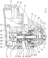
- FIG. 1 shows a section through the entire hand shower, on the basis of which the various inner water paths for the several operating modes in which the hand shower can be operated will first be explained.
- the hand shower shown comprises, in a manner known per se, a housing 1 which is expanded in a bell-shaped manner in its area 1a on the left in the drawing and passes into a handle 1b in its right-hand region, which has largely been broken off in FIG. 1.
- the handle 1b is hollow; its interior 2 is used to supply the water, as is common in hand showers.
- the bell-shaped area 1a of the housing 1 is closed at the bottom by a shower base 3.
- a shower base 3 is composed of an outer layer 3a made of an elastomeric material, which serves as a shock protection plate, and an inner rigid layer 3b.
- the shower base 3 is provided with two sets of water outlet openings 4, 5, which are arranged in concentric circles around the central axis of the shower base 3.
- the water outlet openings 4 have a relatively small cross section; they are located at the outer end of a hose-like nozzle insert 6, which extends relatively far into the interior of the housing 1.
- This nozzle insert 6 is also made of elastomeric material.
- the water outlet openings 5, which have a relatively large cross section, are located at the outer end of hose-like nozzle inserts 7, which, however, only extend into the interior of the housing 1 over a relatively short distance.
- the hose-like nozzle inserts 7 also consist of elastomeric material.
- An insert 8 is fastened in the interior of the bell-shaped region 1 a of the housing 1. This is a relatively complicated molded part, which is shown in one piece in the drawing, but in practice is generally composed of several parts.
- the insert 8 can be roughly divided into an area 8a running parallel to the shower base 3 and one Subdivide the essentially cylindrical extension 8b from the rear of this area 8a in FIG. 1 and upwards.
- the cylindrical extension 8b is inserted into a cylindrical wall 9 molded onto the housing 1, sealed against it by an O-ring 10 and fixed in a suitable manner in the axial direction to the shower base 3 - for example by gluing or latching (not shown).
- the shower base 3 is fastened to the insert 8 and thus to the housing 1 by a central fastening screw 11, which is screwed into a central stepped bore 12 of the insert 8.
- a first annular space 13 is located within the cylindrical insert 8b. It is connected to a radial through opening 14 in the ring wall 9 of the housing 1 pointing in the direction of the handle 1b.
- the annular space 13 also communicates via a plurality of through bores 15 which are provided in its annular base with a second annular space 16 which opens into a water distribution space 17 which extends parallel to the shower base 3 and essentially over its entire surface.
- the water distribution space 17 communicates with the inner ends of the hose-like nozzle inserts 7, which belong to the water outlet openings 5 with a larger cross section.
- a third annular space 18 is recessed, which connects to a fourth annular space 20 via a plurality of through bores 19 distributed over the circumference stands.
- the fourth annular space 20 concentrically surrounds the third annular space 18 with a larger radius.
- through-bores 21 are provided coaxially with each hose-like nozzle insert 6 and are surrounded at their outer end by small cylindrical collars 22 which are molded onto the underside of the insert 8.
- the cylindrical collars 22 receive the inner ends of the hose-like nozzle inserts 6; Due to the elastic properties of these hose-like nozzle inserts 6, a tight transition of the water from the fourth annular space 20 to the water outlet openings 4 of small cross-section is ensured in this way.
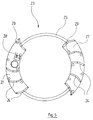
- a pulsator wheel 23 is rotatably mounted in the fourth annular space 20, which - as can also be seen in particular in FIG. 5 - is equipped with a large number of curved turbine blades 24 which extend essentially in the radial direction.
- the pulsator wheel 23 is guided by an integrally formed annular rib 25 which runs in a groove 26 in the bottom surface of the fourth annular space 20.
- the rib 25 of the pulsator wheel 23 carries diametrically opposite two cover ring segments 27 which each extend over an angle of approximately 90 ° parallel to the bottom of the fourth annular space 20 and cover the through bores 21 in the corresponding peripheral region of the annular space 20.
- an axially projecting stop 28 is also formed between the turbine wheels 24. In a manner to be described, this serves to block the pulsator wheel 23 in a specific rotational position.
- many small through holes 29 are also provided, which are each aligned with a through hole 21 of the insert 8 in the blocking position of the pulsator wheel 23 mentioned.
- a first valve seat 30 directed axially downward is formed in the housing 1 of the hand shower between the interior 2 of the handle 1b and the through opening 14.
- a second valve seat 31 is located coaxially to the first valve seat 30 on a cylindrical collar 32 of the insert 8, which is inserted into a complementary opening 33 of the housing 1 and sealed against it by an O-ring 34.
- the second valve seat 31 is connected to the third annular space 18 via through bores 35.
- the two valve seats 30 and 31 cooperate with an axially movable double valve cone 36, which in turn is composed of a shaft part 37 and the actual seal 38, which cooperates with the valve seats 30 and 31.
- the stem part 37 of the double valve plug 36 is made through an opening 39 from the housing 1, a molded seal 40 arranged between the outer surface of the stem part 37 and a corresponding housing wall preventing water from escaping from the interior of the housing 1.
- the outer end of the shaft part 37 is connected to a changeover mechanism, which is provided overall with the reference number 41, is partially housed in a recess 42 on the top of the housing 1 and is described in more detail below.
- the double valve plug 36 is acted upon by a compression spring 43, which is clamped between a step of the shaft part 37 and a washer 44 supported on the housing 1, such that the seal 38 of the double valve plug is normally in the position shown in FIG closes the second valve seat 31.
- the entire double valve plug 36 is coaxially penetrated by a stop rod 45. This has its lower end passed through a bore 46 which leads into the fourth annular space 20.
- the stop rod 45 can be moved axially within the double valve cone 36. It can assume two positions: in the first position, which is shown in FIG. 1, the lower end of the stop rod 45 projects into the fourth annular space 20 so that it is in the path of movement of the stop 28 of the pulsator wheel 23. When the stop 28 comes into contact with the lower end of the stop rod 45, the through bores 29 provided in the cover segment 27 are aligned with the through bores 21 of the insert 8.
- the stop rod 45 In the second axial position, the stop rod 45 is moved so far up that its lower end is no longer in the path of movement of the stop 28 of the pulsator wheel 23, so that the pulsator wheel 23 can be rotated completely freely.
- the first operating mode of the hand shower is shown in Figure 1 and in Figures 2a to 2c.
- the second valve seat 31 is closed by the double valve cone 36.
- the water flowing in via the interior 2 of the handle 1b flows past the first valve seat through the through opening 14 of the wall 9 of the housing 1 into the first annular space 13 of the insert 8b. From there, the water flows further through the openings 15 into the second annular space 16, into the water distribution space 17 and then over an annular sieve 50, which covers the inner ends of the hose-like nozzle inserts 7, to the outside.
- the water flowing through the passage openings 15 in the form of many individual jets is enriched with air when entering the second annular space 16, which air is sucked in via the radial bores 51 connecting the annular space 16 with the central stepped bore 12, the stepped bore 12 itself and through through bores 52 in the shower base 3 .
- the water flowing out of the water outlet openings 5 is therefore enriched with the finest air bubbles. Because of the relatively large cross section of the water outlet openings 5, the shower jets produced here are relatively slow. They are therefore felt to be soft. One speaks in the professional world therefore also from "soft or soft jet operation”.
- the second operating mode of the shower is obtained when the double valve cone 36 is shifted upwards, that is to say closes the first valve seat 30 and releases the second valve seat 31.
- the stop rod 45 is still in the position in which its lower end prevents the pulsator wheel 23 from rotating freely.
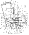
- the relationships are shown in FIGS. 3a to 3c.
- the water flowing in via the interior 2 of the handle 1b flows through the passage openings 35 of the insert 8 into the third annular space 18, from there via the radially directed passage openings 19 into the fourth annular space 20.
- the pulsator wheel 23 is rotated a little by the turbine blades 24 until the stop 28 abuts the stop rod 45. A further rotation of the pulsator wheel 23 is then no longer possible.
- the fourth annular space 20 now acts as a simple water distribution space, from which the water flows via the passage openings 21 in the bottom of the fourth annular space 20 and the hose-like nozzle inserts 6 to the water outlet openings 4.
- the shower jets emerging here are relatively fast because of the geometry of the water outlet openings 4 and are therefore perceived as hard, as well as because of the lack of air enrichment. One speaks therefore of the "hard jet operation" of the hand shower.
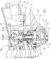
- the double valve plug 36 has the same position as in the second operating mode open: This means that it blocks the first valve seat 30 and releases the second valve seat 31.
- the stop rod 45 on the other hand, is now pulled back axially upward, so that its lower end no longer hinders the rotation of the pulsator wheel 23.
- the water path is the same as in the second operating mode: the water flows via the interior 2 of the handle 1b past the second valve seat 31 through the through openings 35 into the third annular space 18, from there via the radial through openings 19 into the fourth annular space 20 and out of it Via the through openings 21 and the hose-like nozzle inserts 6 to the water outlet openings 4 of small cross-section.
- the part of the changeover mechanism accommodated in the recess 42 of the housing 1 comprises 41 a rocker-type manual operating element 53, hereinafter referred to as "rocker".
- the rocker 53 closes the recess 42 of the housing 1 upwards and protrudes only so far that it can be easily operated.
- An actuating finger 54 protruding into the interior of the recess 42 is formed on the rocker 53. This is penetrated in its upper region by a pivot pin 55 which is held in the side walls of the housing 1. In this way, the rocker 53 can be pivoted about a horizontal axis defined by the pivot pin 55.
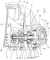
- FIGS. 2a to 2c show the middle position of both the rocker 53 and the slide 56, which corresponds to the first operating mode of the hand shower, that is to say the "soft jet mode".
- a bracket 59 extending approximately parallel to the direction of the arrow 58 is formed, which is provided at its end with an oblique cam surface 60.
- a guide plate 61 with a V-shaped guide slot 62 is formed on each side of the arm 59 of the slide 56.
- the front guide plate 61 is cut according to the cut.
- the interface is identified by the hatched rectangle 68.
- the representation in the region of the upper end of the double valve cone 36 is chosen differently, in such a way that the guide plate 61 actually lying in front of the cutting plane and the way in which it is connected to the extension 59 of the slide 56 can be seen.
- the upper end of the shaft part 37 is spherical, as can be seen in particular from FIG. 2a. It is received by a complementary partially spherical inner surface of a drive ring 63 composed of two parts.
- the driving ring 63 is axially displaceably guided in a cylindrical collar 64 formed on the bottom of the recess 42 of the housing 1.
- two driving pins 65 protrude from the outer surface of the driving ring 63, diametrically opposite, as can be seen in FIGS. 2b and 2c.
- the driving pins 65 are received by the guide slots 62 of the adjacent guide plates 61. This can be seen particularly in FIG. 2c.
- the relative position of the slide 56 and in particular of the V-shaped guide slots 62 provided in the guide plates 61 relative to the upper end of the double valve cone 36 is such that the driving pins 65 are located in the lower apex of the V- shaped guide slots 62 are located.
- Figure 2c This is clearly the position in which the double valve cone 36 can assume the lowest position, in which its seal 38 closes the second valve seat 31. Due to the internal form fit between the shaft part 37 of the double valve plug 36 and the stop rod 45, the latter is also in its lowermost position, in which its lower end projects into the fourth annular space 20.
- the upper end of the stop rod 45 is at a short distance from the cam surface 60 on the arm 59 of the slide 56.
- the double valve plug 36 As can be seen in particular from FIG. 3c, the linear movement of the slide 56 to the left pushes the driving pins 65 of the driving ring 63 into the leg of the V-shaped guide slots 62 on the right in the drawing. Due to the inclination of this leg, the guide pins 65 are pulled up in a kind of cam effect; due to the form fit between The driving ring 63 and the shaft part 37 of the double valve cone 36 follow the latter axially upwards until it closes the first valve seat 30, as shown in FIGS. 3a and 3c. Since, as mentioned, the stop rod 45 remains axially during this axial movement of the double valve cone 36, the compression spring 49 arranged between the double valve cone 36 and the stop rod 45 is compressed.
- the water can flow past the second valve seat 31 via the third annular space 18 into the fourth annular space 20 and from there to the water outlet openings 4, but with the stop rod 45 following as before the rotatability of the pulsator 23 prevents.
- the water flows past the second valve seat 31 and through the third annular space 18 into the fourth annular space 20, where it can set the pulsator wheel 23 in rotation without hindrance.
- the desired pulsed hard jets (pulsator or massage jets) now emerge from the water outlet openings 4 of the shower base 3.
- the compression spring 43 After the water inlet has been shut off, the compression spring 43 returns the double valve cone 36 to the position shown in FIGS. 2a to 2c, which thereby becomes a preferred position.
- the first operating mode is therefore set automatically so that "soft jet operation" is present when the water flows through again.
Landscapes
- Engineering & Computer Science (AREA)
- Mechanical Engineering (AREA)
- Multimedia (AREA)
- Nozzles (AREA)
- Bathtubs, Showers, And Their Attachments (AREA)
- Massaging Devices (AREA)
Applications Claiming Priority (2)
| Application Number | Priority Date | Filing Date | Title |
|---|---|---|---|
| DE19509659 | 1995-03-17 | ||
| DE19509659A DE19509659C1 (de) | 1995-03-17 | 1995-03-17 | Mehrfunktions-Handbrause |
Publications (3)
| Publication Number | Publication Date |
|---|---|
| EP0732148A2 true EP0732148A2 (fr) | 1996-09-18 |
| EP0732148A3 EP0732148A3 (fr) | 1997-04-23 |
| EP0732148B1 EP0732148B1 (fr) | 1999-12-08 |
Family
ID=7756921
Family Applications (1)
| Application Number | Title | Priority Date | Filing Date |
|---|---|---|---|
| EP96102969A Expired - Lifetime EP0732148B1 (fr) | 1995-03-17 | 1996-02-28 | Pomme de douche multifonction |
Country Status (6)
| Country | Link |
|---|---|
| US (1) | US5918816A (fr) |
| EP (1) | EP0732148B1 (fr) |
| JP (1) | JP3751676B2 (fr) |
| AT (1) | ATE187361T1 (fr) |
| DE (1) | DE19509659C1 (fr) |
| ES (1) | ES2142509T3 (fr) |
Cited By (9)
| Publication number | Priority date | Publication date | Assignee | Title |
|---|---|---|---|---|
| EP1132141A2 (fr) | 2000-03-10 | 2001-09-12 | Amfag S.p.a. | Pommeau de douche amovible pour la cuisine |
| EP1837080A1 (fr) * | 2006-03-21 | 2007-09-26 | Fabrizio Nobili | Tête de vaporisation avec activation simplifiée spécialement pour éviers de cuisines |
| CN100435971C (zh) * | 1999-04-08 | 2008-11-26 | 阿尔森斯有限公司 | 淋浴喷头器具组件 |
| WO2009067829A1 (fr) * | 2007-11-27 | 2009-06-04 | Weidmann Plastics Technology Ag | Pomme de douche pouvant fonctionner sélectivement selon deux modes de fonctionnement |
| WO2012041356A1 (fr) * | 2010-10-01 | 2012-04-05 | Grohe Ag | Pomme d'arrosoir |
| DE102013207687A1 (de) * | 2013-04-26 | 2014-10-30 | Hansgrohe Se | Brausekopf mit blockierbarer Steuerscheiben-Drehbewegung |
| RU2620436C2 (ru) * | 2012-07-13 | 2017-05-25 | Хансгрое СЕ | Душевое устройство |
| CN113000236A (zh) * | 2021-02-22 | 2021-06-22 | 福建拓维卫浴有限公司 | 一种带按摩水花的多功能出水装置 |
| US20230079771A1 (en) * | 2010-09-28 | 2023-03-16 | Delta Faucet Company | Showerhead with multi-dimensional fluid dispensers |
Families Citing this family (33)
| Publication number | Priority date | Publication date | Assignee | Title |
|---|---|---|---|---|
| US6715699B1 (en) * | 1999-04-08 | 2004-04-06 | Masco Corporation | Showerhead engine assembly |
| US6607148B1 (en) | 2000-01-13 | 2003-08-19 | Kohler Co. | Shower head |
| US6290147B1 (en) | 2000-09-19 | 2001-09-18 | Moen Incorporated | Pullout faucet wand button mechanism |
| JP3746692B2 (ja) * | 2001-07-31 | 2006-02-15 | 治 三宅 | 浴室用の手持ち式噴霧器 |
| US7070125B2 (en) * | 2003-05-16 | 2006-07-04 | Newfrey Llc | Multi-pattern pull-out spray head |
| ITMN20030043A1 (it) * | 2003-11-14 | 2005-05-15 | Amfag Spa | Doccetta per lavello |
| ITMI20041472A1 (it) * | 2004-07-21 | 2004-10-21 | Fabrizio Nobili | Doccetta per docce in genere ed in particolare per docce manuali per lavelli e simili |
| US7343930B2 (en) | 2004-12-03 | 2008-03-18 | Masco Corporation Of Indiana | Sprayer with non-faucet control |
| US7322535B2 (en) | 2005-01-24 | 2008-01-29 | Newfrey, Llc | Faucet spray head |
| DE502006002331D1 (de) * | 2005-03-11 | 2009-01-22 | Weidmann Plastics Tech Ag | Brausekopf |
| US11267003B2 (en) | 2005-05-13 | 2022-03-08 | Delta Faucet Company | Power sprayer |
| WO2006124721A2 (fr) | 2005-05-13 | 2006-11-23 | Masco Corporation Of Indiana | Pulverisateur puissant |
| EP1736695B1 (fr) * | 2005-06-24 | 2008-07-09 | Weidmann Plastics Technology AG | Vanne, notamment pour une robinetterie sanitaire |
| ITMI20051252A1 (it) * | 2005-07-01 | 2007-01-02 | Fabrizio Nobili | Gruppo per l'erogazione differenziabile di acqua trattata e di acqua di rete |
| US7871020B2 (en) | 2006-01-26 | 2011-01-18 | Masco Corporation Of Indiana | Faucet spray head with volume control |
| US8424781B2 (en) | 2006-02-06 | 2013-04-23 | Masco Corporation Of Indiana | Power sprayer |
| ITMI20060357A1 (it) * | 2006-02-28 | 2007-09-01 | Fabrizio Nobili | Doccetta per lavello con variazione del getto di erogazione e regolazione della portata |
| CN101069877B (zh) * | 2006-05-10 | 2010-05-12 | 周华松 | 花洒的功能切换装置 |
| DE102006025785B3 (de) * | 2006-05-31 | 2007-11-08 | Grohe Ag | Wasserauslaufvorrichtung für eine Sanitärarmatur |
| EP1884693A1 (fr) * | 2006-08-03 | 2008-02-06 | Fabrizio Nobili | Robinet |
| US8152078B2 (en) | 2006-10-25 | 2012-04-10 | Masco Corporation Of Indiana | Faucet spray head |
| WO2009006755A1 (fr) * | 2007-07-09 | 2009-01-15 | Huasong Zhou | Unité de commutation pour un bouton poussoir d'un robinet d'eau de cuisine |
| US7766260B2 (en) * | 2008-02-12 | 2010-08-03 | Wen-Yi Lin | Showerhead |
| US9050612B2 (en) * | 2009-03-19 | 2015-06-09 | Delta Faucet Company | Shower device with independently operating valves |
| US8448667B2 (en) | 2009-10-19 | 2013-05-28 | Masco Corporation Of Indiana | Multi-function pull-out wand |
| DE102010039679A1 (de) * | 2010-08-24 | 2012-03-01 | Hansgrohe Ag | Brause mit einem Gelenk |
| CN102728492B (zh) * | 2011-04-01 | 2014-04-23 | 厦门松霖科技有限公司 | 点触碰切换花洒 |
| US8720800B2 (en) * | 2011-11-17 | 2014-05-13 | Wei-Sheng WU | Shower head |
| US9545639B2 (en) | 2013-03-15 | 2017-01-17 | Delta Faucet Company | Multi-function wand assembly |
| EP2982280A4 (fr) * | 2013-04-05 | 2017-10-18 | Hirohiko Sato | Tringlerie et dispositif de douche l'utilisant |
| WO2014190881A1 (fr) * | 2013-05-27 | 2014-12-04 | 厦门松霖科技有限公司 | Poignee rotative de commutation de pomme de douche |
| CN104549802B (zh) * | 2014-12-26 | 2018-05-08 | 厦门松霖科技股份有限公司 | 出水装置及包括该出水装置的花洒 |
| CN119554472B (zh) * | 2024-08-16 | 2025-10-21 | 箭牌家居集团股份有限公司 | 出水装置 |
Family Cites Families (16)
| Publication number | Priority date | Publication date | Assignee | Title |
|---|---|---|---|---|
| US3473736A (en) * | 1967-09-13 | 1969-10-21 | Charles J Heitzman | Pulsating device for water outlet fixtures |
| US4010899A (en) * | 1975-11-19 | 1977-03-08 | Heitzman Charles J | Pulsating fluid spray device |
| GB1591718A (en) * | 1976-12-06 | 1981-06-24 | Hexagear Ind Ltd | Shower heads |
| US4588130A (en) * | 1984-01-17 | 1986-05-13 | Teledyne Industries, Inc. | Showerhead |
| DE3413552A1 (de) * | 1984-04-11 | 1985-10-24 | Hansa Metallwerke Ag, 7000 Stuttgart | Brause |
| US4629125A (en) * | 1984-08-27 | 1986-12-16 | Fuyi Liu | Spray nozzle |
| DE3509602C3 (de) * | 1985-03-16 | 1997-04-30 | Hansa Metallwerke Ag | Satz von Handbrausen |
| US4754928A (en) * | 1987-01-14 | 1988-07-05 | Alsons Corporation | Variable massage showerhead |
| DE3707885A1 (de) * | 1987-03-12 | 1988-09-22 | Grohe Kg Hans | Brausekopf |
| US4903897A (en) * | 1988-08-12 | 1990-02-27 | L. R. Nelson Corporation | Turret nozzle with ball valve flow adjustment |
| DE3902588C1 (fr) * | 1989-01-28 | 1990-03-15 | Ideal-Standard Gmbh, 5300 Bonn, De | |
| US5100055A (en) * | 1989-09-15 | 1992-03-31 | Modern Faucet Mfg. Co. | Spray valve with constant actuating force |
| DE4116927A1 (de) * | 1991-05-24 | 1992-11-26 | Grohe Armaturen Friedrich | Brause |
| AT405490B (de) * | 1992-11-09 | 1999-08-25 | Ideal Standard | Multifunktionsbrausekopf |
| US5397064A (en) * | 1993-10-21 | 1995-03-14 | Heitzman; Charles J. | Shower head with variable flow rate, pulsation and spray pattern |
| US5356077A (en) * | 1994-01-10 | 1994-10-18 | Shames Sidney J | Pulsating shower head |
-
1995
- 1995-03-17 DE DE19509659A patent/DE19509659C1/de not_active Expired - Fee Related
-
1996
- 1996-02-28 AT AT96102969T patent/ATE187361T1/de active
- 1996-02-28 EP EP96102969A patent/EP0732148B1/fr not_active Expired - Lifetime
- 1996-02-28 ES ES96102969T patent/ES2142509T3/es not_active Expired - Lifetime
- 1996-03-15 JP JP05950596A patent/JP3751676B2/ja not_active Expired - Fee Related
- 1996-03-18 US US08/617,206 patent/US5918816A/en not_active Expired - Lifetime
Cited By (16)
| Publication number | Priority date | Publication date | Assignee | Title |
|---|---|---|---|---|
| CN100435971C (zh) * | 1999-04-08 | 2008-11-26 | 阿尔森斯有限公司 | 淋浴喷头器具组件 |
| EP1132141A3 (fr) * | 2000-03-10 | 2003-01-22 | Amfag S.p.a. | Pommeau de douche amovible pour la cuisine |
| CN1292837C (zh) * | 2000-03-10 | 2007-01-03 | 艾姆法格股份公司 | 厨房用可拉出式喷水头 |
| EP1132141A2 (fr) | 2000-03-10 | 2001-09-12 | Amfag S.p.a. | Pommeau de douche amovible pour la cuisine |
| EP1837080A1 (fr) * | 2006-03-21 | 2007-09-26 | Fabrizio Nobili | Tête de vaporisation avec activation simplifiée spécialement pour éviers de cuisines |
| WO2009067829A1 (fr) * | 2007-11-27 | 2009-06-04 | Weidmann Plastics Technology Ag | Pomme de douche pouvant fonctionner sélectivement selon deux modes de fonctionnement |
| CN101878068B (zh) * | 2007-11-27 | 2012-11-28 | 魏德曼塑料技术股份有限公司 | 用于在至少两个工作模式中可选择地工作的喷头 |
| US20230079771A1 (en) * | 2010-09-28 | 2023-03-16 | Delta Faucet Company | Showerhead with multi-dimensional fluid dispensers |
| US9539590B2 (en) | 2010-10-01 | 2017-01-10 | Grohe Ag | Spray head |
| WO2012041356A1 (fr) * | 2010-10-01 | 2012-04-05 | Grohe Ag | Pomme d'arrosoir |
| RU2534088C1 (ru) * | 2010-10-01 | 2014-11-27 | Гроэ Аг | Душевая головка |
| RU2620436C2 (ru) * | 2012-07-13 | 2017-05-25 | Хансгрое СЕ | Душевое устройство |
| US9295996B2 (en) | 2013-04-26 | 2016-03-29 | Hansgrohe Se | Shower head with blockable control disc rotary movement |
| DE102013207687A1 (de) * | 2013-04-26 | 2014-10-30 | Hansgrohe Se | Brausekopf mit blockierbarer Steuerscheiben-Drehbewegung |
| CN113000236A (zh) * | 2021-02-22 | 2021-06-22 | 福建拓维卫浴有限公司 | 一种带按摩水花的多功能出水装置 |
| CN113000236B (zh) * | 2021-02-22 | 2021-11-23 | 福建拓维卫浴有限公司 | 一种带按摩水花的多功能出水装置 |
Also Published As
| Publication number | Publication date |
|---|---|
| DE19509659C1 (de) | 1996-11-21 |
| JP3751676B2 (ja) | 2006-03-01 |
| EP0732148A3 (fr) | 1997-04-23 |
| JPH08256932A (ja) | 1996-10-08 |
| EP0732148B1 (fr) | 1999-12-08 |
| ATE187361T1 (de) | 1999-12-15 |
| ES2142509T3 (es) | 2000-04-16 |
| US5918816A (en) | 1999-07-06 |
Similar Documents
| Publication | Publication Date | Title |
|---|---|---|
| EP0732148B1 (fr) | Pomme de douche multifonction | |
| EP0732147B1 (fr) | Pomme de douche multifonction | |
| EP0284801B1 (fr) | Pomme de douche | |
| DE2911405C2 (de) | Massagebrause mit einer Einrichtung zur wahlweisen Erzeugung pulsierender und/oder nicht pulsierender Flüssigkeitsstrahlen | |
| EP0696476B1 (fr) | Douche | |
| EP2699357B1 (fr) | Pomme de douche ou douchette | |
| EP2227337B1 (fr) | Pomme de douche pouvant fonctionner sélectivement selon deux modes de fonctionnement | |
| EP3457010B1 (fr) | Dériveur de fluide | |
| DE2615872A1 (de) | Duschkopf zur erzeugung stetiger oder pulsierender strahlen | |
| DE102013213275B4 (de) | Sanitäres Schaltventil und Brausekopf | |
| EP2699358B1 (fr) | Pomme de douche ou douchette | |
| DE4330535C1 (de) | Sanitäres Einhebel-Mischventil | |
| DE4118540A1 (de) | Handbrause | |
| EP1281899B1 (fr) | Dispositif de changement de régime pour dispositif sanitaire avec au moins deux utilisateurs | |
| DE102011003050B4 (de) | Sanitäres Abschalt- bzw. Umschaltventil | |
| EP0591877B1 (fr) | Douche avec pomme de douche autonettoyante | |
| DE1477589B2 (de) | Positioniereinrichtung. Ausscheidung aus: 1774982 | |
| DE8118264U1 (de) | Sanitaer-mischbatterie | |
| DE202018104944U1 (de) | Brauseumstellventil und Sanitärbrause | |
| DE10135555B4 (de) | Umstellvorrichtung für eine Sanitäreinrichtung mit mindestens zwei Wasserverbrauchern | |
| EP3074138B1 (fr) | Disque à jet de douche et pomme de douche | |
| DE102012216959B4 (de) | Handbrause | |
| DE3335756A1 (de) | Handbrause | |
| EP2926913A1 (fr) | Pomme dotée d'un dispositif de commutation | |
| DE102009044215A1 (de) | Regner |
Legal Events
| Date | Code | Title | Description |
|---|---|---|---|
| PUAI | Public reference made under article 153(3) epc to a published international application that has entered the european phase |
Free format text: ORIGINAL CODE: 0009012 |
|
| AK | Designated contracting states |
Kind code of ref document: A2 Designated state(s): AT CH ES FR GB IT LI |
|
| PUAL | Search report despatched |
Free format text: ORIGINAL CODE: 0009013 |
|
| AK | Designated contracting states |
Kind code of ref document: A3 Designated state(s): AT CH ES FR GB IT LI |
|
| 17P | Request for examination filed |
Effective date: 19970703 |
|
| 17Q | First examination report despatched |
Effective date: 19980619 |
|
| GRAG | Despatch of communication of intention to grant |
Free format text: ORIGINAL CODE: EPIDOS AGRA |
|
| GRAG | Despatch of communication of intention to grant |
Free format text: ORIGINAL CODE: EPIDOS AGRA |
|
| GRAH | Despatch of communication of intention to grant a patent |
Free format text: ORIGINAL CODE: EPIDOS IGRA |
|
| GRAH | Despatch of communication of intention to grant a patent |
Free format text: ORIGINAL CODE: EPIDOS IGRA |
|
| GRAA | (expected) grant |
Free format text: ORIGINAL CODE: 0009210 |
|
| AK | Designated contracting states |
Kind code of ref document: B1 Designated state(s): AT CH ES FR GB IT LI |
|
| REF | Corresponds to: |
Ref document number: 187361 Country of ref document: AT Date of ref document: 19991215 Kind code of ref document: T |
|
| REG | Reference to a national code |
Ref country code: CH Ref legal event code: EP |
|
| GBT | Gb: translation of ep patent filed (gb section 77(6)(a)/1977) |
Effective date: 19991208 |
|
| REG | Reference to a national code |
Ref country code: CH Ref legal event code: NV Representative=s name: FREI PATENTANWALTSBUERO |
|
| ITF | It: translation for a ep patent filed | ||
| ET | Fr: translation filed | ||
| REG | Reference to a national code |
Ref country code: ES Ref legal event code: FG2A Ref document number: 2142509 Country of ref document: ES Kind code of ref document: T3 |
|
| PLBE | No opposition filed within time limit |
Free format text: ORIGINAL CODE: 0009261 |
|
| STAA | Information on the status of an ep patent application or granted ep patent |
Free format text: STATUS: NO OPPOSITION FILED WITHIN TIME LIMIT |
|
| 26N | No opposition filed | ||
| REG | Reference to a national code |
Ref country code: GB Ref legal event code: IF02 |
|
| PGFP | Annual fee paid to national office [announced via postgrant information from national office to epo] |
Ref country code: GB Payment date: 20020214 Year of fee payment: 7 |
|
| PG25 | Lapsed in a contracting state [announced via postgrant information from national office to epo] |
Ref country code: GB Free format text: LAPSE BECAUSE OF NON-PAYMENT OF DUE FEES Effective date: 20030228 |
|
| GBPC | Gb: european patent ceased through non-payment of renewal fee | ||
| PGFP | Annual fee paid to national office [announced via postgrant information from national office to epo] |
Ref country code: FR Payment date: 20110311 Year of fee payment: 16 Ref country code: IT Payment date: 20110224 Year of fee payment: 16 Ref country code: AT Payment date: 20110225 Year of fee payment: 16 Ref country code: CH Payment date: 20110225 Year of fee payment: 16 |
|
| PGFP | Annual fee paid to national office [announced via postgrant information from national office to epo] |
Ref country code: ES Payment date: 20110224 Year of fee payment: 16 |
|
| REG | Reference to a national code |
Ref country code: CH Ref legal event code: PL |
|
| PG25 | Lapsed in a contracting state [announced via postgrant information from national office to epo] |
Ref country code: LI Free format text: LAPSE BECAUSE OF NON-PAYMENT OF DUE FEES Effective date: 20120229 Ref country code: CH Free format text: LAPSE BECAUSE OF NON-PAYMENT OF DUE FEES Effective date: 20120229 |
|
| REG | Reference to a national code |
Ref country code: FR Ref legal event code: ST Effective date: 20121031 |
|
| PG25 | Lapsed in a contracting state [announced via postgrant information from national office to epo] |
Ref country code: IT Free format text: LAPSE BECAUSE OF NON-PAYMENT OF DUE FEES Effective date: 20120228 |
|
| REG | Reference to a national code |
Ref country code: AT Ref legal event code: MM01 Ref document number: 187361 Country of ref document: AT Kind code of ref document: T Effective date: 20120228 |
|
| PG25 | Lapsed in a contracting state [announced via postgrant information from national office to epo] |
Ref country code: AT Free format text: LAPSE BECAUSE OF NON-PAYMENT OF DUE FEES Effective date: 20120228 Ref country code: FR Free format text: LAPSE BECAUSE OF NON-PAYMENT OF DUE FEES Effective date: 20120229 |
|
| REG | Reference to a national code |
Ref country code: ES Ref legal event code: FD2A Effective date: 20130708 |
|
| PG25 | Lapsed in a contracting state [announced via postgrant information from national office to epo] |
Ref country code: ES Free format text: LAPSE BECAUSE OF NON-PAYMENT OF DUE FEES Effective date: 20120229 |