EP0732153A2 - Dispositif vibrateur torsionnel pour un arbre rotatif - Google Patents
Dispositif vibrateur torsionnel pour un arbre rotatif Download PDFInfo
- Publication number
- EP0732153A2 EP0732153A2 EP96103759A EP96103759A EP0732153A2 EP 0732153 A2 EP0732153 A2 EP 0732153A2 EP 96103759 A EP96103759 A EP 96103759A EP 96103759 A EP96103759 A EP 96103759A EP 0732153 A2 EP0732153 A2 EP 0732153A2
- Authority
- EP
- European Patent Office
- Prior art keywords
- shaft
- coupled
- supporting elements
- constituted
- springs
- Prior art date
- Legal status (The legal status is an assumption and is not a legal conclusion. Google has not performed a legal analysis and makes no representation as to the accuracy of the status listed.)
- Granted
Links
Images


Classifications
-
- B—PERFORMING OPERATIONS; TRANSPORTING
- B06—GENERATING OR TRANSMITTING MECHANICAL VIBRATIONS IN GENERAL
- B06B—METHODS OR APPARATUS FOR GENERATING OR TRANSMITTING MECHANICAL VIBRATIONS OF INFRASONIC, SONIC, OR ULTRASONIC FREQUENCY, e.g. FOR PERFORMING MECHANICAL WORK IN GENERAL
- B06B1/00—Methods or apparatus for generating mechanical vibrations of infrasonic, sonic, or ultrasonic frequency
- B06B1/10—Methods or apparatus for generating mechanical vibrations of infrasonic, sonic, or ultrasonic frequency making use of mechanical energy
-
- Y—GENERAL TAGGING OF NEW TECHNOLOGICAL DEVELOPMENTS; GENERAL TAGGING OF CROSS-SECTIONAL TECHNOLOGIES SPANNING OVER SEVERAL SECTIONS OF THE IPC; TECHNICAL SUBJECTS COVERED BY FORMER USPC CROSS-REFERENCE ART COLLECTIONS [XRACs] AND DIGESTS
- Y10—TECHNICAL SUBJECTS COVERED BY FORMER USPC
- Y10T—TECHNICAL SUBJECTS COVERED BY FORMER US CLASSIFICATION
- Y10T74/00—Machine element or mechanism
- Y10T74/19—Gearing
- Y10T74/19633—Yieldability in gear trains
-
- Y—GENERAL TAGGING OF NEW TECHNOLOGICAL DEVELOPMENTS; GENERAL TAGGING OF CROSS-SECTIONAL TECHNOLOGIES SPANNING OVER SEVERAL SECTIONS OF THE IPC; TECHNICAL SUBJECTS COVERED BY FORMER USPC CROSS-REFERENCE ART COLLECTIONS [XRACs] AND DIGESTS
- Y10—TECHNICAL SUBJECTS COVERED BY FORMER USPC
- Y10T—TECHNICAL SUBJECTS COVERED BY FORMER US CLASSIFICATION
- Y10T74/00—Machine element or mechanism
- Y10T74/19—Gearing
- Y10T74/19642—Directly cooperating gears
- Y10T74/19698—Spiral
- Y10T74/19828—Worm
Definitions
- the present invention relates to a device for subjecting a shaft to a combined simple rotation and alternating rotation of limited extent about its own axis.
- This so-called balling and burlapping operation currently entails the use of an arc-shaped blade that is subjected to a combined simple rotation and alternating rotation of limited extent about its own axis.
- the simple rotation combined with the alternating vibratory motion, allows the blade to penetrate the soil and to isolate the sod from said soil.
- Each one of the two movements is actuated by corresponding actuation means, for example a hydraulic motor for rotary motion and a torsional oscillation generator for vibratory motion.
- actuation means for example a hydraulic motor for rotary motion and a torsional oscillation generator for vibratory motion.
- a principal aim of the present invention is to provide a device for subjecting a shaft to a combined simple rotation and alternating rotation of limited extent about its own axis that is not subject to breakages due to fatigue of parts during use.
- a consequent primary object is to provide a device that can be conveniently installed on equipment for performing the balling and burlapping of plants.
- Another object is to provide a device that can be manufactured with conventional equipment and facilities.
- a device comprising elastic means that are arranged diametrically opposite with respect to a shaft that is coupled to a generator of torsional vibrations, said elastic means being rigidly coupled between first supporting elements that rotate with said shaft and second supporting elements that are rigidly coupled to a gear system that is freely mounted on said shaft and is coupled to means for actuating rotation.
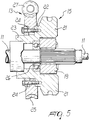
- a shaft 11 is rotatably coupled to a frame 10, and a curved blade, not shown in the figures, for performing for example the balling and burlapping of plants is conveniently fixed on the head 11a of said shaft.
- Said shaft 11 is subjected to a combined motion that includes a simple rotation, by means of a hydraulic motor 12 and of a worm gear reduction unit 13, and an alternating rotation of limited extent, by means of a torsional vibration generator 14.
- the device 15 described hereinafter comprises in this case four cylindrical helical springs 16 arranged in parallel pairs and in diametrically opposite positions so as to substantially surround the shaft 11.
- the springs 16 are rigidly coupled between first supporting elements, generally designated by the reference numeral 17, and second supporting elements, generally designated by the reference numeral 18.
- the first supporting elements 17 are constituted, in this case, by a rocker 19 with two arms 20 extending in opposite directions; said rocker 19 is rigidly coupled coaxially, by means of a splined coupling, to the shaft 11.
- the second supporting elements 18 are constituted, in this embodiment, by wings 21 extending axially, in diametrically opposite positions, from the flange-fitted end 22 of a shaped tubular element 23 that is fixed by means of bolts 24 to a ring gear 25 of the reduction unit 13.
- the tubular element 23 and the ring gear 25 are coaxial to the shaft 11 upon assembly; the tubular element 23 is furthermore associated with said shaft 11 by bearing systems generally designated by the reference numeral 26.
- the reduction unit 13 constituted by the ring gear 25 and by the worm gear 27 receives its driving motion from the hydraulic motor 12.
- each one of the springs 16 has an end that is fixed to a corresponding wing 21 by means of a corresponding threaded element 28, whereas the other end is fixed to a dome-shaped part 29 that is slidingly coupled to an appropriately complementarily shaped region 30 of a corresponding one of the arms 20.
- the threaded element 28 accommodated in a corresponding seat 31 formed in the corresponding wing 21 engages a bush 32 that is accommodated snugly and coaxially inside the respective spring 16.
- Coupling between the dome-shaped part 29 and the corresponding complementarily shaped region 30 is ensured by a rod-like element 33 that is pivoted in a cavity 34 formed in the corresponding arm 20 and, upon assembly, is inserted in a hole 35 formed in the dome-shaped part 29, where said rod-like element 33, by having an end that can open in a fork-like manner, determines the anchoring of said end to the dome-shaped part 29.
- the materials employed may be any according to the requirements.
Landscapes
- Engineering & Computer Science (AREA)
- Mechanical Engineering (AREA)
- Apparatuses For Generation Of Mechanical Vibrations (AREA)
- Hydraulic Motors (AREA)
- Connection Of Motors, Electrical Generators, Mechanical Devices, And The Like (AREA)
- Toys (AREA)
- Soil Working Implements (AREA)
- Friction Gearing (AREA)
- Gear Transmission (AREA)
Applications Claiming Priority (2)
| Application Number | Priority Date | Filing Date | Title |
|---|---|---|---|
| IT1995PD000018U IT239102Y1 (it) | 1995-03-14 | 1995-03-14 | Dispositivo per sottoporre un albero ad un movimento combinato dirotazione semplice e di rotazione alternata, di ampiezza ridotta, |
| ITPD950018U | 1995-03-14 |
Publications (3)
| Publication Number | Publication Date |
|---|---|
| EP0732153A2 true EP0732153A2 (fr) | 1996-09-18 |
| EP0732153A3 EP0732153A3 (fr) | 1997-07-02 |
| EP0732153B1 EP0732153B1 (fr) | 1999-12-01 |
Family
ID=11390902
Family Applications (1)
| Application Number | Title | Priority Date | Filing Date |
|---|---|---|---|
| EP96103759A Expired - Lifetime EP0732153B1 (fr) | 1995-03-14 | 1996-03-11 | Dispositif vibrateur torsionnel pour un arbre rotatif |
Country Status (6)
| Country | Link |
|---|---|
| US (1) | US5771744A (fr) |
| EP (1) | EP0732153B1 (fr) |
| CA (1) | CA2171794A1 (fr) |
| DE (1) | DE69605340T2 (fr) |
| ES (1) | ES2140737T3 (fr) |
| IT (1) | IT239102Y1 (fr) |
Cited By (3)
| Publication number | Priority date | Publication date | Assignee | Title |
|---|---|---|---|---|
| EP0791406A1 (fr) * | 1996-02-20 | 1997-08-27 | Holmac S.a.s. di Gastaldi Christian & C. | Dispositif vibrateur torsionnel pour un arbre rotatif |
| CN104653738A (zh) * | 2015-02-11 | 2015-05-27 | 曲绍毅 | 一种可振动的蜗轮蜗杆减速机 |
| CN111570246A (zh) * | 2020-05-25 | 2020-08-25 | 南京工程学院 | 一种间歇轴向扭转复合式机械扭振台 |
Families Citing this family (8)
| Publication number | Priority date | Publication date | Assignee | Title |
|---|---|---|---|---|
| US6135889A (en) * | 1996-02-20 | 2000-10-24 | Holmac S.A.S. Di Gastaldi Christian & C. | Device for subjecting a shaft to a combined simple rotation and alternating rotation of limited extent about its own axis |
| US5905154A (en) * | 1996-06-10 | 1999-05-18 | American Cyanamid Company | Process for the preparation of 5-(alkoxymethyl)-2,3-pyridinedicarboximide compounds |
| US6408572B1 (en) * | 1998-06-03 | 2002-06-25 | Mitsuba Corporation | Driving gear |
| JP2001271903A (ja) * | 2000-01-17 | 2001-10-05 | Honda Motor Co Ltd | 作業機の動力伝達装置 |
| EP2406522B1 (fr) * | 2009-03-10 | 2013-04-17 | Illinois Tool Works Inc. | Engranage à vis sans fin et hypoide hybride |
| US20130061704A1 (en) * | 2011-09-09 | 2013-03-14 | Illinois Tool Works Inc. | Enveloping spiroid gear assemblies and method of manufacturing the same |
| US9234549B2 (en) * | 2013-09-13 | 2016-01-12 | Paladin Brands Group, Inc. | Torsional coupling for a mobile attachment device |
| US20160091052A1 (en) * | 2014-09-25 | 2016-03-31 | Moatech Co., Ltd. | Actuator and electronic equipment having the same |
Family Cites Families (12)
| Publication number | Priority date | Publication date | Assignee | Title |
|---|---|---|---|---|
| US1510943A (en) * | 1924-04-10 | 1924-10-07 | Kjelsberg Olaf | Resilient gear wheel |
| US2005974A (en) * | 1931-10-24 | 1935-06-25 | Packard Motor Car Co | Power transmission system |
| GB418783A (en) * | 1933-10-02 | 1934-10-31 | Cesare Fontana | Improvements in or relating to variable speed gearing |
| FR775014A (fr) * | 1934-06-18 | 1934-12-18 | Changement de vitesse dynamométrique et progressif | |
| FR1148842A (fr) * | 1956-03-05 | 1957-12-16 | Changement de vitesse | |
| US3461969A (en) * | 1966-05-20 | 1969-08-19 | Bodine Albert G | Sonic subsurface soil cultivator |
| FR1604413A (fr) * | 1968-11-28 | 1971-11-08 | ||
| US4616713A (en) * | 1984-11-29 | 1986-10-14 | Shattuck Thomas G | Blade adjustment device for sod cutting machine |
| JPS6420428A (en) * | 1987-07-15 | 1989-01-24 | Fujitsu Ltd | Formation of acicular member |
| US4871027A (en) * | 1988-07-07 | 1989-10-03 | J. I. Case Company | Multiple-edge sod cutter for vibratory plow |
| FR2655115B1 (fr) * | 1989-11-30 | 1993-01-22 | Valeo | Amortisseur de vibrations, notamment pour vehicule automobile. |
| JPH0646089Y2 (ja) * | 1990-02-02 | 1994-11-24 | 原田工業株式会社 | 電動伸縮形アンテナ駆動装置 |
-
1995
- 1995-03-14 IT IT1995PD000018U patent/IT239102Y1/it active
-
1996
- 1996-03-11 DE DE69605340T patent/DE69605340T2/de not_active Expired - Fee Related
- 1996-03-11 ES ES96103759T patent/ES2140737T3/es not_active Expired - Lifetime
- 1996-03-11 EP EP96103759A patent/EP0732153B1/fr not_active Expired - Lifetime
- 1996-03-12 US US08/614,414 patent/US5771744A/en not_active Expired - Lifetime
- 1996-03-14 CA CA002171794A patent/CA2171794A1/fr not_active Abandoned
Cited By (4)
| Publication number | Priority date | Publication date | Assignee | Title |
|---|---|---|---|---|
| EP0791406A1 (fr) * | 1996-02-20 | 1997-08-27 | Holmac S.a.s. di Gastaldi Christian & C. | Dispositif vibrateur torsionnel pour un arbre rotatif |
| CN104653738A (zh) * | 2015-02-11 | 2015-05-27 | 曲绍毅 | 一种可振动的蜗轮蜗杆减速机 |
| CN111570246A (zh) * | 2020-05-25 | 2020-08-25 | 南京工程学院 | 一种间歇轴向扭转复合式机械扭振台 |
| CN111570246B (zh) * | 2020-05-25 | 2021-06-01 | 南京工程学院 | 一种间歇轴向扭转复合式机械扭振台 |
Also Published As
| Publication number | Publication date |
|---|---|
| ITPD950018V0 (it) | 1995-03-14 |
| ITPD950018U1 (it) | 1996-09-14 |
| CA2171794A1 (fr) | 1996-09-15 |
| EP0732153B1 (fr) | 1999-12-01 |
| IT239102Y1 (it) | 2001-02-19 |
| US5771744A (en) | 1998-06-30 |
| DE69605340T2 (de) | 2000-07-13 |
| ES2140737T3 (es) | 2000-03-01 |
| EP0732153A3 (fr) | 1997-07-02 |
| DE69605340D1 (de) | 2000-01-05 |
Similar Documents
| Publication | Publication Date | Title |
|---|---|---|
| EP0732153B1 (fr) | Dispositif vibrateur torsionnel pour un arbre rotatif | |
| US5305738A (en) | Massage device | |
| US6325327B1 (en) | Anti-vibration suspension device with torsion springs between vibrators and structure, for a helicopter | |
| BRPI0711528A2 (pt) | turbina de vento | |
| DE3344315A1 (de) | Abgestimmtes gyroskop mit dynamischem absorber | |
| RU2274565C2 (ru) | Привод стеклоочистителя | |
| EP0233724A2 (fr) | Sonde ultrasonore pour le diagnostic médical | |
| JP2739581B2 (ja) | バイパスファン用可変ピッチ制御装置 | |
| EP0142205A1 (fr) | Couvercle pour un dispositif de pelage à la vapeur | |
| US3145257A (en) | Adjustable rear vision mirror | |
| EP0399503B1 (fr) | Appareil faucheur du type oscillatoire | |
| CN105966613B (zh) | 用于悬挂动力传递装置系杆的防振动悬架系统、悬架结构及飞行器 | |
| JP4637998B2 (ja) | 切断した作物の処理装置と、この処理装置を用いる草刈り機 | |
| DE753502C (de) | Antriebsvorrichtung zur Erregung mechanischer, technische Arbeit leistender, schwingungsfaehiger Systeme | |
| CA2285898C (fr) | Engrenage de champ destine en particulier aux aeronefs | |
| DE2742560A1 (de) | Schwingungstilger | |
| EP3646988A1 (fr) | Support, machine et procédé de finition de surface | |
| EP3146231A1 (fr) | Amortisseur de rotation | |
| KR100710640B1 (ko) | 아이스 크러셔 용 감속기 | |
| EP0791406B1 (fr) | Dispositif vibrateur torsionnel pour un arbre rotatif | |
| US6135889A (en) | Device for subjecting a shaft to a combined simple rotation and alternating rotation of limited extent about its own axis | |
| US3395563A (en) | Forging machine | |
| US2616238A (en) | Hedge cutter | |
| US3494206A (en) | Locking means | |
| KR970010618B1 (ko) | 수직 다관절 로보트의 베이스부 구조 |
Legal Events
| Date | Code | Title | Description |
|---|---|---|---|
| PUAI | Public reference made under article 153(3) epc to a published international application that has entered the european phase |
Free format text: ORIGINAL CODE: 0009012 |
|
| AK | Designated contracting states |
Kind code of ref document: A2 Designated state(s): DE ES FR NL |
|
| PUAL | Search report despatched |
Free format text: ORIGINAL CODE: 0009013 |
|
| AK | Designated contracting states |
Kind code of ref document: A3 Designated state(s): DE ES FR NL |
|
| RTI1 | Title (correction) | ||
| 17P | Request for examination filed |
Effective date: 19971219 |
|
| GRAG | Despatch of communication of intention to grant |
Free format text: ORIGINAL CODE: EPIDOS AGRA |
|
| 17Q | First examination report despatched |
Effective date: 19990201 |
|
| GRAG | Despatch of communication of intention to grant |
Free format text: ORIGINAL CODE: EPIDOS AGRA |
|
| GRAH | Despatch of communication of intention to grant a patent |
Free format text: ORIGINAL CODE: EPIDOS IGRA |
|
| GRAH | Despatch of communication of intention to grant a patent |
Free format text: ORIGINAL CODE: EPIDOS IGRA |
|
| GRAA | (expected) grant |
Free format text: ORIGINAL CODE: 0009210 |
|
| AK | Designated contracting states |
Kind code of ref document: B1 Designated state(s): DE ES FR NL |
|
| REF | Corresponds to: |
Ref document number: 69605340 Country of ref document: DE Date of ref document: 20000105 |
|
| ET | Fr: translation filed | ||
| REG | Reference to a national code |
Ref country code: ES Ref legal event code: FG2A Ref document number: 2140737 Country of ref document: ES Kind code of ref document: T3 |
|
| PLBE | No opposition filed within time limit |
Free format text: ORIGINAL CODE: 0009261 |
|
| STAA | Information on the status of an ep patent application or granted ep patent |
Free format text: STATUS: NO OPPOSITION FILED WITHIN TIME LIMIT |
|
| 26N | No opposition filed | ||
| PGFP | Annual fee paid to national office [announced via postgrant information from national office to epo] |
Ref country code: ES Payment date: 20020228 Year of fee payment: 7 |
|
| PGFP | Annual fee paid to national office [announced via postgrant information from national office to epo] |
Ref country code: FR Payment date: 20020326 Year of fee payment: 7 |
|
| PGFP | Annual fee paid to national office [announced via postgrant information from national office to epo] |
Ref country code: NL Payment date: 20020329 Year of fee payment: 7 |
|
| PGFP | Annual fee paid to national office [announced via postgrant information from national office to epo] |
Ref country code: DE Payment date: 20020430 Year of fee payment: 7 |
|
| PG25 | Lapsed in a contracting state [announced via postgrant information from national office to epo] |
Ref country code: ES Free format text: LAPSE BECAUSE OF NON-PAYMENT OF DUE FEES Effective date: 20030312 |
|
| PG25 | Lapsed in a contracting state [announced via postgrant information from national office to epo] |
Ref country code: NL Free format text: LAPSE BECAUSE OF NON-PAYMENT OF DUE FEES Effective date: 20031001 Ref country code: DE Free format text: LAPSE BECAUSE OF NON-PAYMENT OF DUE FEES Effective date: 20031001 |
|
| PG25 | Lapsed in a contracting state [announced via postgrant information from national office to epo] |
Ref country code: FR Free format text: LAPSE BECAUSE OF NON-PAYMENT OF DUE FEES Effective date: 20031127 |
|
| NLV4 | Nl: lapsed or anulled due to non-payment of the annual fee |
Effective date: 20031001 |
|
| REG | Reference to a national code |
Ref country code: FR Ref legal event code: ST |
|
| REG | Reference to a national code |
Ref country code: ES Ref legal event code: FD2A Effective date: 20030312 |