EP0732185B1 - Dispositif d'injection amélioré-bloc de distribution pour une machine d'injection - Google Patents
Dispositif d'injection amélioré-bloc de distribution pour une machine d'injection Download PDFInfo
- Publication number
- EP0732185B1 EP0732185B1 EP96301389A EP96301389A EP0732185B1 EP 0732185 B1 EP0732185 B1 EP 0732185B1 EP 96301389 A EP96301389 A EP 96301389A EP 96301389 A EP96301389 A EP 96301389A EP 0732185 B1 EP0732185 B1 EP 0732185B1
- Authority
- EP
- European Patent Office
- Prior art keywords
- manifold
- nozzle
- nozzle housing
- clamp ring
- ring
- Prior art date
- Legal status (The legal status is an assumption and is not a legal conclusion. Google has not performed a legal analysis and makes no representation as to the accuracy of the status listed.)
- Expired - Lifetime
Links
Images

Classifications
-
- B—PERFORMING OPERATIONS; TRANSPORTING
- B29—WORKING OF PLASTICS; WORKING OF SUBSTANCES IN A PLASTIC STATE IN GENERAL
- B29C—SHAPING OR JOINING OF PLASTICS; SHAPING OF MATERIAL IN A PLASTIC STATE, NOT OTHERWISE PROVIDED FOR; AFTER-TREATMENT OF THE SHAPED PRODUCTS, e.g. REPAIRING
- B29C45/00—Injection moulding, i.e. forcing the required volume of moulding material through a nozzle into a closed mould; Apparatus therefor
- B29C45/17—Component parts, details or accessories; Auxiliary operations
- B29C45/26—Moulds
- B29C45/27—Sprue channels ; Runner channels or runner nozzles
-
- B—PERFORMING OPERATIONS; TRANSPORTING
- B29—WORKING OF PLASTICS; WORKING OF SUBSTANCES IN A PLASTIC STATE IN GENERAL
- B29C—SHAPING OR JOINING OF PLASTICS; SHAPING OF MATERIAL IN A PLASTIC STATE, NOT OTHERWISE PROVIDED FOR; AFTER-TREATMENT OF THE SHAPED PRODUCTS, e.g. REPAIRING
- B29C45/00—Injection moulding, i.e. forcing the required volume of moulding material through a nozzle into a closed mould; Apparatus therefor
- B29C45/17—Component parts, details or accessories; Auxiliary operations
- B29C45/26—Moulds
- B29C45/27—Sprue channels ; Runner channels or runner nozzles
- B29C2045/2762—Seals between nozzle and manifold
-
- B—PERFORMING OPERATIONS; TRANSPORTING
- B29—WORKING OF PLASTICS; WORKING OF SUBSTANCES IN A PLASTIC STATE IN GENERAL
- B29C—SHAPING OR JOINING OF PLASTICS; SHAPING OF MATERIAL IN A PLASTIC STATE, NOT OTHERWISE PROVIDED FOR; AFTER-TREATMENT OF THE SHAPED PRODUCTS, e.g. REPAIRING
- B29C45/00—Injection moulding, i.e. forcing the required volume of moulding material through a nozzle into a closed mould; Apparatus therefor
- B29C45/17—Component parts, details or accessories; Auxiliary operations
- B29C45/26—Moulds
- B29C45/27—Sprue channels ; Runner channels or runner nozzles
- B29C2045/2772—Means for fixing the nozzle to the manifold
Definitions
- the present invention relates to an improved manifold-nozzle assembly for use in an injection molding machine for manufacturing molded plastic articles, which assembly includes a clamp ring arrangement for clamping a nozzle housing against a manifold while permitting the nozzle housing to slide against the manifold as a result of thermal expansion.
- U.S. Patent No. 4,588,367 to Schad illustrates a system wherein a spring arrangement for pushing the nozzle against the manifold is used to provide plastic sealing pressure.
- This arrangement works well for smaller nozzles having relatively small melt channels which do not create large separating forces between the nozzle and the manifold.
- the separation forces become much greater due to the increased projected area of the larger melt channel subjected to the pressure of the plastic melt.
- a satisfactory spring design for large nozzle systems would be prohibitively large and cumbersome.
- the mold plates must be precision machined to ensure that the spring pressures are sufficient and consistent.
- U.S. Patent No. 4,981,431 to Schmidt illustrates a nozzle which is directly screwed onto a manifold. Threads are provided in the back face of the nozzle and screws passing through the manifold hold the nozzle tightly to it, providing a preload to aid against plastic leakage at the melt channel interface.
- This design incorporates a nozzle flange and opposing pressure pad which act to squeeze the manifold and nozzle housing together during thermal expansion. As shown in this patent, the nozzle is centered and axially located in the mold plate while the manifold is allowed to expand as it heats up to operating temperature. The expansion of the manifold causes sliding between the manifold front face and the nozzle back face.
- U.S. Patent No. 4,832,593 to Brown shows a method to isolate the screws from travelling while still providing a clamping or sealing force between the nozzle and manifold.
- a manifold cap provides a resting surface for the screw heads and is keyed to a nozzle extension so that neither the screw head nor the screw thread is required to move laterally during thermal expansion of the manifold.
- This design can be overly bulky as it must reach out over and around the hot runner manifold to grip it like a vise. Also, freedom of manifold design is not permitted in the area directly over the nozzle as it must be sized and shaped to receive the nozzle extension and the manifold cap.
- U.S. Patent No. 4,793,795 to Schmidt et al. shows a method of locating a nozzle spigot in the side of a manifold and holding it against the manifold using arcuately shaped members fastened with screws through the manifold.
- This design has a number of shortcomings.
- the nozzle will actually be lifted as well as pushed laterally. Because the nozzle front portion forms part of the molding surface, it will be necessary to perform complex calculations to determine how much movement will be observed at the nozzle tip. The tip design will need to compensate for all movements caused axially and laterally, due to thermal expansion of the manifold. Additionally, the nozzle is more difficult to manufacture with a side mounting spigot feature and the manifold is also more expensive to make, needing a mating counterbore to receive the nozzle spigot.
- EP-A-264723 discloses an assembly for use in an injection molding machine comprising a nozzle housing having a channel through which liquified material is arranged to flow, the nozzle housing being positioned within a bore in a first mold plate.
- a nozzle is provided at one end of the nozzle housing which is connected to a source of liquified material by a channel in a manifold.
- a bushing is provided between the manifold and the mold back plate and serves to maintain the manifold in place, to seal against substantial melt leakage and to collect any melt that does escape.
- this prior arrangement does not provide an effective sealing between the manifold and the nozzle.
- a further bushing is provided between the nozzle and the mold back plate, said bushing having an interior surface profile that matches the exterior surface profile of the nozzle.
- the nozzle is clamped to the manifold through the said further bushing, the clamping force being generated by screws going through both the manifold and the said further bushing. Because there is no gap between the bushing and the nozzle, any lateral displacement of the manifold caused by thermal expansion will be inherently transferred to the nozzle via the bushing and there is, thus, no relative movement between the nozzle and the manifold. Damage to the nozzle is therefore likely to occur with this arrangement.
- the present invention aims to provide a nozzle - manifold assembly which provides a predetermined and consistent sealing force between the nozzle housing and the manifold and which is more flexible and adaptable to manufacturing variances.
- an assembly for use in an injection molding machine for manufacturing molded articles in which the assembly comprises a nozzle housing having a first flow channel through which liquified material is arranged to flow; said nozzle housing being positioned within a bore in a first mold plate; said first flow channel having a nozzle at a first end which is adapted to be connected to a source of liquified material by a second flow channel in a manifold; and means for clamping said nozzle housing against said manifold to prevent leakage of said liquified material as said material flows from said second flow channel to said first flow channel, said clamping means comprising a clamp ring surrounding a portion of said nozzle housing and means for joining said clamp ring to said manifold and thereby creating a clamping force which maintains a seal between the nozzle housing and said manifold, sliding means being provided to permit lateral movement between a first surface of the nozzle housing and a first surface of the manifold caused by heating of the manifold
- the said first surface of the nozzle housing is thus able to slide along the said flat surface of the manifold as a result of thermal expansion.
- FIG. 1 shows a nozzle-manifold assembly 10 which has utility in an injection molding machine for manufacturing molded plastic articles.
- the assembly 10 includes a nozzle housing 12 having a flow channel 14 extending therethrough.
- the flow channel communicates with a nozzle tip 16 seated within an end portion of the nozzle housing.
- the design of the nozzle tip and the manner in which the nozzle tip is seated within the nozzle housing are not pertinent to the instant invention.
- the nozzle tip may have any suitable design known in the art and may be seated in the nozzle housing in any desired manner.
- the nozzle housing 12 is positioned within a well or bore 20 in a first mold plate 18. The manner in which the nozzle housing is positioned within the bore 20 will be discussed hereinafter.
- the nozzle housing 12 is preferably surrounded by heater elements 22.
- the heater elements 22 serve to maintain the liquified material flowing through the channel 14 in a liquified or molten state.
- the heater elements 22 may comprise any suitable heaters or heater arrangement known in the art.
- the assembly 12 further comprises a manifold 24, preferably located between the first mold plate 18 and a second mold plate 26.
- the manifold 24 has a flow channel 28 which communicates with a source (not shown) of the liquified material. As shown in FIG. 1, one end of the channel 28 is aligned with and communicates with an end of the channel 14 so as to facilitate flow of the liquified material from the source to the nozzle tip for injection through a gate 30 into a mold space (not shown).
- the nozzle housing 12 has a substantially flat rear face 32 abutting a substantially flat front face 34 of the manifold 24.
- the nozzle housing 12 is pressed up against the manifold 24 by an annular clamp ring 36 which completely surrounds an enlarged upper portion 44 of the nozzle housing 12.
- the ring 36 has a side wall portion 38 with an annular lip 40. The lip 40 abuts and engages an annular surface 42 formed by the enlarged, upper portion 44 of the nozzle housing 12.
- the side wall portion 38 is spaced from the outer periphery of the upper portion 44 by a gap G so as to allow for relative lateral movement between the clamp ring 36 and nozzle housing 12.
- a gap G so as to allow for relative lateral movement between the clamp ring 36 and nozzle housing 12.
- a desired clamping force is generated between the nozzle housing 12 and the manifold 24 by screws 46 which are inserted through bores 48 in the manifold and threaded into threaded bores 50 within the side wall portion 38 of the clamp ring 36.
- the number and position of the screws can be adapted to suit the individual application. Depending on the size of the flow channels and the injection pressure, more screws or larger screws may be employed to obtain a desired clamping force and thereby maintain an effective seal between the nozzle housing 12 and the manifold 24.
- the nozzle - manifold assembly further includes a nozzle centering ring 52 positioned adjacent the clamp ring 36. As shown in FIG. 1, the ring 52 is preferably located within the upper portion of the bore 20. To properly position the nozzle housing 12, the centering ring 52 has an inner diameter substantially equal to the outer diameter of the main body 15 of the nozzle housing and an outer diameter substantially equal to the diameter of the upper portion of the bore 20 in which the ring 52 resides.
- manifold insulators 70 are employed on opposing faces of the manifold 24 to insure that the housing 12 is appropriately positioned within the mold plate 18.
- the manifold insulators 70 are positioned between the surfaces of the manifold 24 and adjacent surfaces of mold plates 18 and 26.
- the insulators 70 may be formed from any suitable insulating material known in the art and may be joined to the manifold in any desired manner such as by screws 71. If the mold plates 18 and 26 are not accurately machined to size at the location in which the manifold insulators 70 rest, the insulators may be independently and quickly resized to an appropriate length that will position the manifold 24 and housing 12 correctly.
- manifold insulators 70 may be provided only on the manifold surface facing mold plate 18. In this case, screws 72 will maintain the position of manifold front surface 32 and thereby fix the longitudinal position of nozzle housing 12 in the mold plate 18.
- metal treatments or coatings may be used. Local or surface hardening of the sliding surfaces 32 and 34 can reduce metal galling.
- a surface treatment by implantation or coating of slip inducing elements such as molybdenum disulfide may be used.
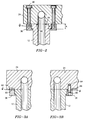
- FIG. 2 shows an alternative embodiment of the assembly of FIG. 1 wherein an additional sealing ring 54 is used to establish a desired sealing force and prevent leakage of the liquified material or molten plastic flowing between the manifold and the nozzle housing.
- the ring 54 may be a metal O-ring which is positioned within a groove 56 in the surface 32 of the nozzle housing. When a clamping force is applied to the nozzle housing by the clamp ring 36 and the screws 46, the O-ring 54 is compressed and serves to substantially prevent liquified material such as molten plastic from leaking past it.
- the ring 54 could be made from a material having a higher rate of thermal expansion than the material forming the nozzle housing 12 and thereby, as the assembly heats up, provide an increased sealing force against leakage of the liquified material.
- the clamp ring 36 could be designed with a sidewall dimension A which is only slightly less than the extent B of the upper portion of the nozzle housing 12 so that the clamp ring 36 is only nominally deformed by the screws 46 when they are tightened.
- the screws 46 will draw the ring 36 against the manifold surface 34 where the ring will be prevented from further bending or flexing. This will serve to provide a predetermined, maximum clamp force between the nozzle housing and the manifold interface, regardless of any over tightening of the screws, and also prevent the clamp ring from being overly deformed to the point of damage, should the screws be tightened too much.
- the ring 36 can be diametrically or otherwise located into the manifold 24 as shown in FIG. 3A by seating a portion 60 of the ring 36 in a groove 62 machined into the surface 34 of the manifold 24.
- a dowel arrangement such as that shown in FIG. 3B can be used.
- the dowel arrangement involves providing the manifold 24 with a plurality of bores 64 into which dowels 66 are inserted and providing the clamp ring 36 with a plurality of bores 68 for receiving the dowels 66. It should be noted that either of the arrangements of FIG. 3A or 3B are used in conjunction with the screws 46 for joining the clamp ring 36 to the manifold and are used to further lock the clamp ring 36 to the manifold.
- An injection molding machine typically will have a plurality of nozzles receiving liquified material or molten plastic from a flow channel or flow channels within a central manifold. Therefore, in a machine using the nozzle - manifold assembly of the present invention, the nozzle housings 12 would be loosely attached to the manifold 24 using clamp rings 36. Next, the manifold 24, with the loosely attached nozzles, would be lowered into position in the mold plate 18. The nozzle front portion or tip 16 and the nozzle centering ring 52 will find their center in the mold plate wells or bores 20, as the clamp ring permits the nozzle housing to freely slide in the lateral direction. Once the manifold insulators 70 have found their resting position and the nozzles are centrally located, the screws 46 can be tightened.
- the manifold 24 will expand laterally with respect to the nozzle housings 12.
- the nozzles will remain centered in their wells or bores 20, located in place by the nozzle centering ring 52 and the nozzle tip 16. Sliding will take place between the nozzle housing back face 32 and the manifold front face 34. Sliding will also take place between either the clamp ring 36 and manifold 24 or the clamp ring 36 and the nozzle housing 12, depending on whether features such as that shown in FIGS. 3A and 3B are employed.
- nozzle-manifold assembly employing a clamp ring to secure the nozzle housing to the manifold.
- the use of a separate clamp ring permits the nozzle housing to have a rear diameter only slightly larger than the main nozzle body, thereby saving metal material during manufacturing and saving time in cutting a minimal amount of material from the original bar stock to achieve the final shape of the nozzle.
- the clamp ring of the present invention can be designed to butt up against the manifold once the ideal clamping force is achieved thereby limiting the force to a designed maximum amount.
- the assembly of the present invention eliminates the need for the mold plate to have a closely controlled bore depth. This is because it is not required to generate any sealing force.
- the assembly of the present invention is further advantageous in that it is easily adaptable to large mold designs and permits easy manufacturing, assembly and preparation. This is because of the simple and compact way in which this new assembly works.
- the centering ring may be omitted if desired.
- the clamp ring 36 can be provided with an outer diameter substantially equal to the diameter of that portion of the well or bore 20 in which it resides so that the outer edge of the clamp ring abuts the interior wall of the bore 20.
Landscapes
- Engineering & Computer Science (AREA)
- Manufacturing & Machinery (AREA)
- Mechanical Engineering (AREA)
- Injection Moulding Of Plastics Or The Like (AREA)
- Moulds For Moulding Plastics Or The Like (AREA)
Claims (17)
- Ensemble destiné à être utilisé dans une machine de moulage par injection pour la fabrication d'articles moulés, comprenant un logement de buse (12) présentant un premier canal d'écoulement (14) par l'intermédiaire duquel du matériau liquéfié est amené à s'écouler, ledit logement de buse étant positionné à l'intérieur d'un alésage (20) dans une première plaque de moule (18), ledit premier canal d'écoulement comportant une buse (16) au niveau d'une première extrémité, qui est conçue pour être reliée à une source de matériau liquéfié par un second canal d'écoulement (28) dans un distributeur (24), et un moyen destiné à serrer ledit logement de buse contre ledit distributeur afin d'empêcher la fuite dudit matériau liquéfié lorsque ledit matériau s'écoule depuis ledit second canal d'écoulement vers ledit premier canal d'écoulement, ledit moyen de serrage comprenant un anneau de serrage (36) entourant une partie dudit logement de buse et des moyens (46, 48, 50) destinés à fixer ledit anneau de serrage audit distributeur et à créer ainsi une force de serrage qui maintient un joint étanche entre le logement de buse et ledit distributeur, caractérisé en ce que sont prévus des moyens coulissants afin de permettre un déplacement latéral entre une première surface (32) du logement de buse (12) et une première surface (34) dudit distributeur (24) provoqué par le chauffage du distributeur.
- Ensemble selon la revendication 1, caractérisé en ce que l'anneau de serrage (36) présente une première surface s'étendant de façon pratiquement parallèle à une seconde surface du logement de buse (12) et en ce que le moyen coulissant comprend la première surface de l'anneau de serrage (36) qui est espacée de la seconde surface du logement de buse (12) ainsi qu'un interstice (G) entre lesdites surfaces afin de permettre ledit mouvement latéral entre la première surface (32) du logement de buse et la première surface (34) du distributeur.
- Ensemble selon l'une quelconque des revendications précédentes, caractérisé en ce que ledit moyen de fixation comprend au moins deux vis (46) vissées dans l'anneau de serrage (36).
- Ensemble selon l'une quelconque des revendications précédentes, caractérisé en ce qu'au moins deux broches (66) logées dans des alésages (64) du distributeur (24) sont conçues afin de s'engager dans des alésages (68) à l'intérieur de l'anneau de serrage (36), lesdites broches (66) empêchant un mouvement coulissant de l'anneau de serrage (36) vis-à-vis du distributeur (24).
- Ensemble selon l'une quelconque des revendications 1 à 3, caractérisé en ce que le distributeur (24) est muni d'une gorge (62) qui est conçue pour recevoir une partie correspondante (60) de l'anneau de serrage (36) de manière à empêcher le mouvement coulissant de l'anneau de serrage vis-à-vis du distributeur.
- Ensemble selon l'une quelconque des revendications précédentes, caractérisé en ce que des moyens sont prévus afin de centrer le support de buse (12) à l'intérieur de l'alésage (20).
- Ensemble selon la revendication 6, caractérisé en ce que le moyen de centrage comprend un anneau de centrage (52) entourant une partie de corps principale du logement de buse (12), ledit anneau de centrage étant positionné à proximité immédiate de l'anneau de serrage (36).
- Ensemble selon la revendication 6, caractérisé en ce que le moyen de centrage comprend ledit anneau de serrage (36) qui comporte un bord externe qui vient en butée contre la paroi intérieure de l'alésage (20) dans la première plaque de moule (18).
- Ensemble selon l'une quelconque des revendications précédentes, caractérisé en ce qu'une gorge (54) est usinée dans le logement de buse (12) et un joint torique (56) est positionné à l'intérieur de ladite gorge afin d'accroítre l'étanchéité entre le logement de buse et le distributeur (24), ledit joint torique (56) venant en contact avec une surface dudit distributeur et étant comprimé d'une valeur prédéterminée par la force de serrage créée par ledit moyen de fixation afin d'empêcher davantage ledit matériau liquéfié de fuir au-delà dudit joint torique, et ledit joint torique étant fait d'un matériau présentant un taux de dilatation thermique plus élevé que le matériau formant ledit logement de buse, afin d'assurer un effet d'étanchéité accru vis-à-vis d'une fuite dudit matériau liquéfié.
- Ensemble selon l'une quelconque des revendications précédentes, caractérisé en ce que l'anneau de serrage (36) présente une dimension de paroi latérale (A) qui n'est que légèrement inférieure à l'étendue d'une partie supérieure (B) du logement de buse (12) de manière à empêcher une déformation substantielle dudit anneau de serrage lorsque lesdits moyens de fixation sont serrés.
- Ensemble selon l'une quelconque des revendications précédentes, caractérisé en ce que des isolateurs de distributeur (70) sont positionnés entre une surface de la première plaque de moule (18) et une surface du distributeur (24) de manière à permettre le positionnement du logement de buse (12) dans l'alésage (20).
- Ensemble selon l'une quelconque des revendications 1 à 10, caractérisé en ce qu'une seconde plaque de moule (26) est prévue, et en ce que des isolateurs de distributeur (70) sont positionnés entre des surfaces desdites première et seconde plaques de moule et des surfaces du distributeur (24) de manière à permettre le positionnement du logement de buse (12) dans l'alésage (20).
- Ensemble selon l'une quelconque des revendications précédentes, caractérisé en ce que la première surface (32) du logement de buse (12) comprend une surface d'extrémité pratiquement plate (32) et la première surface (34) du distributeur (24) comprend une surface pratiquement plate, ladite première surface dudit logement de buse pouvant coulisser le long de ladite surface pratiquement plate dudit collecteur en raison d'une dilatation thermique.
- Procédé de moulage par injection comprenant les étapes consistant à : prévoir un distributeur à canal chauffé (24) en communication fluidique avec une buse d'injection (12), ledit distributeur (24) présentant une première surface de contact (34) et la buse d'injection (12) présentant une seconde face de contact (32), positionner ladite première surface de contact (34) à proximité immédiate de ladite seconde face de contact (32) et en butée contre celle-ci, chauffer le distributeur (24) et la buse (12) afin de maintenir un matériau fondu à l'état chauffé, serrer une partie supérieure de ladite buse d'injection (12) contre le distributeur (24) à l'aide d'un moyen de serrage (36) de manière à empêcher la fuite du matériau fondu lorsqu'il s'écoule depuis le distributeur jusque dans la buse, et prévoir un moyen coulissant destiné à permettre un mouvement de coulissement latéral entre lesdites première et seconde surfaces de contact, résultant de ladite étape de chauffage, tout en empêchant la fuite du matériau fondu, et injecter le matériau fondu depuis ladite buse d'injection dans un espace de cavité.
- Procédé selon la revendication 14, caractérisé en ce que ladite étape consistant à prévoir ledit moyen coulissant comprend la prévision d'un interstice (G) entre une seconde surface de ladite buse d'injection (12) et une surface dudit moyen de serrage (36) pratiquement parallèle à ladite seconde surface de manière à permettre ledit mouvement coulissant latéral.
- Procédé selon la revendication 14 ou la revendication 15, caractérisé en ce que le moyen de serrage est formé par un anneau (36) entourant une partie supérieure de ladite buse (12).
- Procédé selon l'une quelconque des revendications 14 à 16, caractérisé en ce qu'au moins l'une desdites première et seconde surfaces de contact est pourvue de caractéristiques de glissement améliorées.
Applications Claiming Priority (2)
| Application Number | Priority Date | Filing Date | Title |
|---|---|---|---|
| US397851 | 1995-03-02 | ||
| US08/397,851 US5507637A (en) | 1995-03-02 | 1995-03-02 | Hot runner sliding nozzle |
Publications (2)
| Publication Number | Publication Date |
|---|---|
| EP0732185A1 EP0732185A1 (fr) | 1996-09-18 |
| EP0732185B1 true EP0732185B1 (fr) | 1999-02-10 |
Family
ID=23572927
Family Applications (1)
| Application Number | Title | Priority Date | Filing Date |
|---|---|---|---|
| EP96301389A Expired - Lifetime EP0732185B1 (fr) | 1995-03-02 | 1996-02-29 | Dispositif d'injection amélioré-bloc de distribution pour une machine d'injection |
Country Status (5)
| Country | Link |
|---|---|
| US (1) | US5507637A (fr) |
| EP (1) | EP0732185B1 (fr) |
| AT (1) | ATE176620T1 (fr) |
| CA (1) | CA2170565C (fr) |
| DE (1) | DE69601508T2 (fr) |
Families Citing this family (23)
| Publication number | Priority date | Publication date | Assignee | Title |
|---|---|---|---|---|
| US5896640A (en) * | 1996-11-12 | 1999-04-27 | Husky Injection Molding Systems Ltd. | Deflection sealing apparatus and method |
| US5945139A (en) * | 1997-06-30 | 1999-08-31 | Siemens Energy & Automation, Inc. | Injection mold live runner apparatus |
| WO1999037461A1 (fr) * | 1998-01-21 | 1999-07-29 | Protool Ag | Manchon mobile distributeur de la matiere plastique fondue permettant de compenser la dilatation thermique entre le canal de carotte chauffe et l'entree du moule |
| US6062842A (en) * | 1998-04-14 | 2000-05-16 | Larry J. Winget | Mold for use in a gas-assisted injection molding system and runner shut-off subsystem for use therein |
| CA2239349A1 (fr) * | 1998-05-29 | 1999-11-29 | Denis Babin | Appareil d'injection muni de buses a brides de fixation allongees |
| NL1012925C2 (nl) * | 1999-08-27 | 2001-02-28 | Franciscus Antonius Jozef Van | Spuitgietinrichting. |
| US6669462B1 (en) | 2000-05-19 | 2003-12-30 | Husk, Injection Molding Systems Ltd. | Hot runner sealing apparatus |
| CA2437447C (fr) * | 2001-02-28 | 2007-09-18 | Husky Injection Molding Systems Ltd. | Corps de buse amovible et procede |
| DE60328263D1 (de) * | 2002-02-04 | 2009-08-20 | Mold Masters 2007 Ltd | Thermische abdichtung zwischen verteiler und düse |
| US7413131B2 (en) * | 2003-08-25 | 2008-08-19 | Husky Injection Molding Systems Ltd. | Hot runner system components of two materials and method of manufacture |
| EP1663607B1 (fr) * | 2003-09-09 | 2013-06-12 | Mold-Masters (2007) Limited | Dispositif assurant une etancheite entre une buse d'injection a canaux chauffants et un collecteur |
| US7160100B2 (en) | 2004-01-06 | 2007-01-09 | Mold-Masters Limited | Injection molding apparatus having an elongated nozzle incorporating multiple nozzle bodies in tandem |
| CA2482254A1 (fr) * | 2004-04-07 | 2005-10-07 | Mold-Masters Limited | Buse d'injection modulaire a isolant thermique |
| US7462030B2 (en) * | 2004-04-07 | 2008-12-09 | Mold-Masters (2007) Limited | Nozzle having a nozzle body with heated and unheated nozzle body segments |
| KR100632876B1 (ko) | 2004-12-30 | 2006-10-13 | 유도실업주식회사 | 노즐과 커넥팅 시스템이 일체로 구성된 매니폴드와 그 제조방법 |
| KR100791909B1 (ko) * | 2006-04-10 | 2008-01-07 | 유도실업주식회사 | 노즐을 직접 매니폴드에 설치함으로써 열팽창으로 인한매니폴드의 이동시 노즐의 이동 방지장치 |
| CA2822814C (fr) | 2011-01-04 | 2015-11-24 | Husky Injection Molding Systems Ltd. | Formes cristallines de 1-[(3r)-6,8-difluoro-3,4-dihydro-2h-1-benzopyran-3-yl] [2-[(benzylamino]ethyle]-2h-imidazole-2-thione et leurs procedes de preparation |
| ES2714280T3 (es) | 2013-12-11 | 2019-05-28 | Mold Masters 2007 Ltd | Sistema de canal caliente de montaje directo |
| US10160148B2 (en) | 2014-03-07 | 2018-12-25 | Husky Injection Molding Systems Ltd. | Manifold system nozzle retention |
| US9272455B2 (en) | 2014-04-30 | 2016-03-01 | Mold-Masters (2007) Limited | Hot runner system sealing arrangement |
| JP6444712B2 (ja) * | 2014-12-02 | 2018-12-26 | 株式会社サタケ | 粒状物色彩選別機のエジェクター |
| WO2022120122A1 (fr) * | 2020-12-04 | 2022-06-09 | Mold-Masters (2007) Limited | Système de canal chauffant |
| EP4124439B8 (fr) * | 2021-07-30 | 2023-10-25 | Witosa GmbH | Buse de canal chaud |
Family Cites Families (9)
| Publication number | Priority date | Publication date | Assignee | Title |
|---|---|---|---|---|
| CA1190018A (fr) * | 1982-07-12 | 1985-07-09 | Jobst U. Gellert | Manchon pour pointeau de moulage par injection, et sa fabrication |
| US4588367A (en) * | 1984-07-16 | 1986-05-13 | Husky Injection Molding Systems Ltd. | Hot runner manifold for injection molding machine |
| CA1252969A (fr) * | 1986-10-15 | 1989-04-25 | Henry J. Rozema | Manchon de scellement et de calage pour le moulage par injection |
| CA1266358A (fr) * | 1987-10-16 | 1990-03-06 | Jobst Ulrich Gellert | Systeme et methode de moulage par injection aux buses tournantes rapportees |
| US4832593A (en) * | 1988-01-25 | 1989-05-23 | Husky Injection Molding Systems Ltd. | Large nozzle for hot runner mold |
| CA1318998C (fr) * | 1989-07-13 | 1993-06-15 | Harald Hans Schmidt | Systeme de moulage par injection a etancheite d'entree annulaire a rebord |
| ATE127069T1 (de) * | 1990-10-12 | 1995-09-15 | Gellert Jobst U | Mehrfachform-spritzgiesssystem. |
| DE4201341C1 (de) * | 1992-01-20 | 1994-01-20 | Incoe Corp | Klemmeinrichtung für Heißkanalverteiler |
| CA2083413C (fr) * | 1992-11-19 | 2000-07-04 | Jobst Ulrich Gellert | Tuyere pour le moulage par injection, comportant un element chauffant, partiellement non chauffe |
-
1995
- 1995-03-02 US US08/397,851 patent/US5507637A/en not_active Expired - Lifetime
-
1996
- 1996-02-28 CA CA002170565A patent/CA2170565C/fr not_active Expired - Fee Related
- 1996-02-29 AT AT96301389T patent/ATE176620T1/de not_active IP Right Cessation
- 1996-02-29 DE DE69601508T patent/DE69601508T2/de not_active Expired - Fee Related
- 1996-02-29 EP EP96301389A patent/EP0732185B1/fr not_active Expired - Lifetime
Also Published As
| Publication number | Publication date |
|---|---|
| US5507637A (en) | 1996-04-16 |
| CA2170565A1 (fr) | 1996-09-03 |
| CA2170565C (fr) | 2000-01-25 |
| EP0732185A1 (fr) | 1996-09-18 |
| ATE176620T1 (de) | 1999-02-15 |
| DE69601508T2 (de) | 1999-07-08 |
| DE69601508D1 (de) | 1999-03-25 |
Similar Documents
| Publication | Publication Date | Title |
|---|---|---|
| US5507637A (en) | Hot runner sliding nozzle | |
| US6860732B2 (en) | Thermal seal between manifold and nozzle | |
| US5374182A (en) | Hot runner manifold bushing | |
| CN1024329C (zh) | 带有弹簧助力注嘴的注射成型系统 | |
| US5896640A (en) | Deflection sealing apparatus and method | |
| WO1998056560A1 (fr) | Actionneur de goupille de soupape | |
| CA2406060C (fr) | Appareil d'etancheite a canaux chauffants ameliore et procede associe | |
| EP0270766B1 (fr) | Mécanisme de commande hydraulique refroidi par un fluide pour le moulage par injection | |
| US7465165B2 (en) | Configurable manifold | |
| US7850442B2 (en) | Edge-gated nozzle | |
| US7927094B2 (en) | Composite nozzle cap | |
| WO2004012923A2 (fr) | Systeme de guidage et d'alignement de goupille de soupape pour appareil de moulage par injection | |
| JPS63149124A (ja) | 射出成形装置 | |
| JPH0236348B2 (fr) | ||
| AU2001237184A1 (en) | Improved hot runner sealing apparatus and method | |
| US5804231A (en) | Expandable hot runner manifold | |
| CA2762462A1 (fr) | Appareil pour moulage par injection | |
| JP2009515731A (ja) | 射出成型用ノズルおよび装置 | |
| US7445444B2 (en) | Insert for an injection molding apparatus | |
| US20180326632A1 (en) | Insert for Use in an Injection Molding Nozzle and Injection Molding Nozzle with Such an Insert | |
| CA2637181C (fr) | Buse de canal chauffant munie d'un joint a bague fractionnee | |
| US7258541B2 (en) | Thermal expansion compensation support |
Legal Events
| Date | Code | Title | Description |
|---|---|---|---|
| PUAI | Public reference made under article 153(3) epc to a published international application that has entered the european phase |
Free format text: ORIGINAL CODE: 0009012 |
|
| AK | Designated contracting states |
Kind code of ref document: A1 Designated state(s): AT CH DE IT LI NL |
|
| 17P | Request for examination filed |
Effective date: 19961125 |
|
| 17Q | First examination report despatched |
Effective date: 19971204 |
|
| GRAG | Despatch of communication of intention to grant |
Free format text: ORIGINAL CODE: EPIDOS AGRA |
|
| GRAG | Despatch of communication of intention to grant |
Free format text: ORIGINAL CODE: EPIDOS AGRA |
|
| GRAH | Despatch of communication of intention to grant a patent |
Free format text: ORIGINAL CODE: EPIDOS IGRA |
|
| GRAH | Despatch of communication of intention to grant a patent |
Free format text: ORIGINAL CODE: EPIDOS IGRA |
|
| GRAA | (expected) grant |
Free format text: ORIGINAL CODE: 0009210 |
|
| AK | Designated contracting states |
Kind code of ref document: B1 Designated state(s): AT CH DE IT LI NL |
|
| REF | Corresponds to: |
Ref document number: 176620 Country of ref document: AT Date of ref document: 19990215 Kind code of ref document: T |
|
| REG | Reference to a national code |
Ref country code: CH Ref legal event code: NV Representative=s name: PATENTANWAELTE GEORG ROEMPLER UND ALDO ROEMPLER Ref country code: CH Ref legal event code: EP |
|
| PGFP | Annual fee paid to national office [announced via postgrant information from national office to epo] |
Ref country code: AT Payment date: 19990226 Year of fee payment: 4 |
|
| PGFP | Annual fee paid to national office [announced via postgrant information from national office to epo] |
Ref country code: DE Payment date: 19990305 Year of fee payment: 4 |
|
| REF | Corresponds to: |
Ref document number: 69601508 Country of ref document: DE Date of ref document: 19990325 |
|
| PLBE | No opposition filed within time limit |
Free format text: ORIGINAL CODE: 0009261 |
|
| STAA | Information on the status of an ep patent application or granted ep patent |
Free format text: STATUS: NO OPPOSITION FILED WITHIN TIME LIMIT |
|
| 26N | No opposition filed | ||
| PG25 | Lapsed in a contracting state [announced via postgrant information from national office to epo] |
Ref country code: LI Free format text: LAPSE BECAUSE OF NON-PAYMENT OF DUE FEES Effective date: 20000229 Ref country code: CH Free format text: LAPSE BECAUSE OF NON-PAYMENT OF DUE FEES Effective date: 20000229 Ref country code: AT Free format text: LAPSE BECAUSE OF NON-PAYMENT OF DUE FEES Effective date: 20000229 |
|
| PG25 | Lapsed in a contracting state [announced via postgrant information from national office to epo] |
Ref country code: NL Free format text: LAPSE BECAUSE OF NON-PAYMENT OF DUE FEES Effective date: 20000901 |
|
| REG | Reference to a national code |
Ref country code: CH Ref legal event code: PL |
|
| NLV4 | Nl: lapsed or anulled due to non-payment of the annual fee |
Effective date: 20000901 |
|
| PG25 | Lapsed in a contracting state [announced via postgrant information from national office to epo] |
Ref country code: DE Free format text: LAPSE BECAUSE OF NON-PAYMENT OF DUE FEES Effective date: 20001201 |
|
| PG25 | Lapsed in a contracting state [announced via postgrant information from national office to epo] |
Ref country code: IT Free format text: LAPSE BECAUSE OF NON-PAYMENT OF DUE FEES Effective date: 20050228 |