EP0732205B1 - Farbkasten für eine Offsetdruckmaschine - Google Patents
Farbkasten für eine Offsetdruckmaschine Download PDFInfo
- Publication number
- EP0732205B1 EP0732205B1 EP96100878A EP96100878A EP0732205B1 EP 0732205 B1 EP0732205 B1 EP 0732205B1 EP 96100878 A EP96100878 A EP 96100878A EP 96100878 A EP96100878 A EP 96100878A EP 0732205 B1 EP0732205 B1 EP 0732205B1
- Authority
- EP
- European Patent Office
- Prior art keywords
- ink fountain
- ink
- floor
- roller
- tempering
- Prior art date
- Legal status (The legal status is an assumption and is not a legal conclusion. Google has not performed a legal analysis and makes no representation as to the accuracy of the status listed.)
- Expired - Lifetime
Links
- 238000007645 offset printing Methods 0.000 title claims description 5
- XAGFODPZIPBFFR-UHFFFAOYSA-N aluminium Chemical compound [Al] XAGFODPZIPBFFR-UHFFFAOYSA-N 0.000 claims abstract description 11
- 229910052782 aluminium Inorganic materials 0.000 claims abstract description 11
- 238000005496 tempering Methods 0.000 claims abstract description 11
- 238000010438 heat treatment Methods 0.000 claims abstract description 6
- 239000004411 aluminium Substances 0.000 claims abstract 3
- 238000000576 coating method Methods 0.000 claims description 14
- 239000011248 coating agent Substances 0.000 claims description 12
- 239000000463 material Substances 0.000 claims description 12
- 238000007639 printing Methods 0.000 claims description 12
- 230000003647 oxidation Effects 0.000 claims description 6
- 238000007254 oxidation reaction Methods 0.000 claims description 6
- 238000001816 cooling Methods 0.000 claims description 4
- 229920001343 polytetrafluoroethylene Polymers 0.000 claims description 4
- 239000004810 polytetrafluoroethylene Substances 0.000 claims description 4
- 229910000831 Steel Inorganic materials 0.000 claims description 3
- 238000001125 extrusion Methods 0.000 claims description 3
- 239000010959 steel Substances 0.000 claims description 3
- 229920001169 thermoplastic Polymers 0.000 claims description 3
- 239000004416 thermosoftening plastic Substances 0.000 claims description 3
- 230000007246 mechanism Effects 0.000 abstract 1
- 239000003973 paint Substances 0.000 description 5
- 238000000034 method Methods 0.000 description 4
- 238000004140 cleaning Methods 0.000 description 3
- XEEYBQQBJWHFJM-UHFFFAOYSA-N Iron Chemical compound [Fe] XEEYBQQBJWHFJM-UHFFFAOYSA-N 0.000 description 2
- 239000003795 chemical substances by application Substances 0.000 description 2
- AZDRQVAHHNSJOQ-UHFFFAOYSA-N alumane Chemical class [AlH3] AZDRQVAHHNSJOQ-UHFFFAOYSA-N 0.000 description 1
- 230000003670 easy-to-clean Effects 0.000 description 1
- 229910052742 iron Inorganic materials 0.000 description 1
- 239000007788 liquid Substances 0.000 description 1
- 238000005192 partition Methods 0.000 description 1
- -1 polytetrafluoroethylene Polymers 0.000 description 1
- 230000035484 reaction time Effects 0.000 description 1
- 239000005871 repellent Substances 0.000 description 1
- 238000007650 screen-printing Methods 0.000 description 1
- 239000007858 starting material Substances 0.000 description 1
Images

Classifications
-
- B—PERFORMING OPERATIONS; TRANSPORTING
- B41—PRINTING; LINING MACHINES; TYPEWRITERS; STAMPS
- B41F—PRINTING MACHINES OR PRESSES
- B41F31/00—Inking arrangements or devices
- B41F31/02—Ducts, containers, supply or metering devices
-
- B—PERFORMING OPERATIONS; TRANSPORTING
- B41—PRINTING; LINING MACHINES; TYPEWRITERS; STAMPS
- B41F—PRINTING MACHINES OR PRESSES
- B41F31/00—Inking arrangements or devices
- B41F31/002—Heating or cooling of ink or ink rollers
-
- B—PERFORMING OPERATIONS; TRANSPORTING
- B41—PRINTING; LINING MACHINES; TYPEWRITERS; STAMPS
- B41F—PRINTING MACHINES OR PRESSES
- B41F31/00—Inking arrangements or devices
- B41F31/02—Ducts, containers, supply or metering devices
- B41F31/04—Ducts, containers, supply or metering devices with duct-blades or like metering devices
Definitions
- the invention relates to an ink fountain for an offset printing machine according to the preamble of the main claim.
- a color box of this type is known from DE 9 310 680.7 U1.
- the color box is in A partition is arranged near the ink duct to form an ink inlet wedge. Color is supplied to the ink inlet wedge, which is directly in front of or in the ink fountain Temperature control devices is tempered.
- the disadvantage here is that a high amount of parts is required.
- an inking roller for a printing press is known, whose interior is flowed through by temperature control agents.
- a temperature-controllable ink fountain which has a multi-part Has structure.
- the actual ink fountain is housed in an insulating housing.
- the invention further includes a color box that quickly reacts the color to a given temperature tempered and at the same time the cleaning effort noticeable when the color changes reduced.
- a color box that quickly reacts the color to a given temperature tempered and at the same time the cleaning effort noticeable when the color changes reduced.
- a block of material for example with main components made of steel or aluminum, through a die (a tool provided with corresponding openings) by means of Press stamp pressed and in this way the ink fountain base is made from one strand generated.
- the ink fountain base is made by a single forming process in its profile generated as a component. The strand then only needs to be of the appropriate length be separated. The change in shape in the forming process also increases the strength properties of the material increased.
- the ink fountain base is preferably additional provided with an oleophobic (color-repellent) coating. It was found, that aluminum or aluminum compounds as the starting material for the ink fountain floor is particularly suitable.
- Thermoplastic coatings are also suitable for further development, for example PTFE layers.
- the plate bottom is a plate / sheet assigned, which consists of an oleophobic material.
- Aluminum is also suitable here or aluminum connections.
- the plates / sheets can preferably be one or several printing plates, for example used printing plates.
- the extruded Ink fountain floor has a very smooth surface on its ink fountain surface (conditionally through the extrusion process and the corresponding material). Through coatings very good cleaning results can be achieved. When using pressure plates the remaining color can be removed with the printing plate when changing the color remove from the ink fountain.
- the side walls can also be made of one material with oleophobic coating, e.g. Aluminum materials.
- oleophobic coating e.g. Aluminum materials.
- the ink fountain according to the invention is particularly suitable with its temperature control device for waterless offset printing (dry offset).
- This color box can be used alone or in combination with a tempered ink fountain roller for use in a printing unit come.
- An inking unit is arranged in a known manner in a printing unit of an offset printing press.
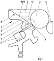
- the inking unit has an ink fountain 1 to which an ink fountain roller 2 is assigned is.
- the ink fountain roller 2 is adjacent to an ink fountain roller 6.
- the ink fountain 1 is on the ink fountain roller 2 can be pivoted and has a plurality of a metering device 5 color dosing elements.
- the metering device 5 acts centrally on the ink fountain roller 2.
- the color box 1 has an ink fountain base 3 and side walls 4. Preferably parallel to Ink fountain roller 2 run in the ink fountain base 3 temperature control devices 7, 8.
- the temperature control devices 7, 8 are designed, for example, as channels which are separated from the temperature control medium are flowed through or the channels accommodate heating / cooling elements. Become the tempering devices 7, 8 flows through a tempering medium, so that is the Ink fountain roller adjacent channel of the temperature control device 7 as a lead for Medium executed. The channel of the tempering device facing away from the ink fountain roller 2 8 then serves as a return line. Depending on the temperature control requirement, several can be used Channels of the temperature control device 7 facing the ink fountain roller 2 and also several Channels of the temperature control device 8 of the ink fountain roller 2 can be arranged facing away. The temperature control devices 7, 8 are close to the ink fountain surface 9 within the ink fountain bottom 3 arranged.
- the ink fountain 1 with ink fountain floor 3 (including ink fountain surface 9) and the channels of the temperature control devices 7, 8 is in one piece as one Extruded profile made.
- the ink fountain surface 9 is already oleophobic.
- the ink fountain surface 9 with an aluminum material as anodic oxidation layer 10 coated.
- the anodic oxidation layer 10 can additionally also on an ink fountain surface 9 made of an aluminum material be applied.
- the use of a preferably used printing plate, inserted on the ink fountain surface 9 represents a further development.
- the ink fountain surface can also 9 an additional coating made of a thermoplastic, e.g. have a PTFE coating (polytetrafluoroethylene).
- the mode of action is as follows:
- the ink fountain 1 is filled with an offset color 12.
- the temperature control devices 7, 8 are flowed through by a temperature control means, which increases or reduces the temperature of the paint depending on the requirement.
- the heat or cold input of the temperature control agent is transferred to the ink 12 via the ink fountain base 3, the ink fountain surface 9.
- the heat or cold input into color 12 takes place analogously.
- the color 12 is removed manually from the ink fountain 1, including the ink fountain side walls 4, using a spatula.
- Paint that is still adhering can be removed outside the ink fountain 1 and the cleaned plate 11 can be placed back in the ink fountain.
- oleophobic material as the ink fountain base 3, ink fountain surface 9, side walls 4 and / or anodic oxidation layers 10, the cleaning times can be noticeably reduced.
Landscapes
- Inking, Control Or Cleaning Of Printing Machines (AREA)
- Impression-Transfer Materials And Handling Thereof (AREA)
Description
- Fig. 1
- eine schematische Darstellung eines Farbkastens
- Fig. 2
- einen Farbkasten mit Beschichtung
- Fig. 3
- einen Farbkasten mit Druckplatte
Der Farbkasten 1 ist mit einer Offsetfarbe 12 gefüllt. Die Temperiereinrichtungen 7, 8 werden von einem Temperiermittel durchströmt, welches die Temperatur der Farbe je nach Anforderung erhöht oder reduziert. Der Wärme- oder Kälteeintrag des Temperiermittels wird über den Farbkastenboden 3, die Farbkastenoberfläche 9 in die Farbe 12 übertragen. Bei Verwendung von Heiz-/Kühlelementen erfolgt der Wärme- bzw. Kälteeintrag in die Farbe 12 analog. Nach Beendigung des Druckvorganges bzw. beim Farbwechsel wird die Farbe 12 manuell mittels Spachtel aus dem Farbkasten 1, einschließlich den Farbkastenseitenwänden 4 entfernt. Bei Verwendung einer Platte 11 wird diese einfach vom Farbkastenboden 3 herausgenommen. Noch anhaftende Farbe läßt sich außerhalb des Farbkastens 1 entfernen und die gereinigte Platte 11 kann wieder in den Farbkasten eingelegt werden. Bei Verwendung von oleophobem Material als Farbkastenboden 3, Farbkastenoberfläche 9, Seitenwänden 4 und/oder anodische Oxydationsschichten 10 lassen sich die Reinigungszeiten spürbar reduzieren.
- 1
- Farbkasten
- 2
- Farbkastenwalze
- 3
- Farbkastenboden
- 4
- Farbkastenseitenwand
- 5
- Dosiereinrichtung
- 6
- Farbheberwalze
- 7
- Temperiereinrichtung
- 8
- Temperiereinrichtung
- 9
- Farbkastenoberfläche
- 10
- anodische Oxydationsschicht
- 11
- Platte
- 12
- Farbe
Claims (12)
- Farbkasten (1) für eine Offsetdruckmaschine, der an eine Farbkastenwalze (2) anstellbar ist und einen Farbkastenboden (3) mit einer der Farbe zugewandten Oberfläche sowie Seitenwände (4) aufweist,
dadurch gekennzeichnet,
daß der Farbkastenboden (3) aus einem einteiligen Strangpreßprofil mit sehr glatter Ausbildung der der Farbe zugewandten Oberfläche besteht, wobei der Farbkastenboden (3) aus Stahl oder Aluminiumwerkstoffbesteht oder Stahl oder Aluminium enthält. - Farbkasten nach Anspruch 1,
dadurch gekennzeichnet,
daß der Farbkastenboden (3) eine Farbkastenoberfläche (9) besitzt, die eine oleophobe Beschichtung aufweist. - Farbkasten nach Anspruch 2,
dadurch gekennzeichnet,
daß die oleophobe Beschichtung eine anodische Oxydationsschicht (10), vorzugsweise eine Eloxalbeschichtung ist. - Farbkasten nach Anspruch 2,
dadurch gekennzeichnet,
daß der Farbkastenboden (3) und die Seitenwände (4) eine oleophobe Beschichtung aufweisen. - Farbkasten nach Anspruch 1,
dadurch gekennzeichnet,
daß der Farbkastenboden (3) eine thermoplastische Beschichtung aufweist, vorzugsweise eine PTFE-Beschichtung. - Farbkasten nach Anspruch 1,
dadurch gekennzeichnet,
daß der Farbkastenboden (3) auf seiner Farbkastenoberfläche (9) eine Platte (11) trägt. - Farbkasten nach Anspruch 6,
dadurch gekennzeichnet,
daß die Platte (11) eine Druckplatte ist, die einer Dosiereinrichtung (5) benachbart lagefixiert ist. - Farbkasten nach Anspruch 1,
dadurch gekennzeichnet,
daß der Farbkasten (1) im Farbkastenboden (3) angeordnete Temperiereinrichtungen (7, 8) aufweist. - Farbkasten nach Anspruch 8,
dadurch gekennzeichnet,
daß die Temperiereinrichtungen (7, 8) parallel zur Farbkastenwalze (2) verlaufende, untereinander verbundene Kanäle sind. - Farbkasten nach den Ansprüchen 8 und 9,
dadurch gekennzeichnet,
daß die Temperiereinrichtungen (7, 8) von einem eingespeisten Temperiermedium durchströmt werden, wobei die der Farbkastenwalze (2) benachbarte kanalförmige Temperiereinrichtung (7) den Vorlaufstrang und die der Farbkastenwalze (2) abgewandte kanalförmige Temperiereinrichtung (8) den Rücklaufstrang bilden. - Farbkasten nach Anspruch 8,
dadurch gekennzeichnet,
daß die in den Farbkastenboden (3) integrierten Temperiereinrichtungen (7, 8) Heiz- bzw. Kühlelemente sind. - Farbkasten nach Anspruch 1 und 8,
dadurch gekennzeichnet,
daß die Farbkastenwalze (2) temperiert ist.
Applications Claiming Priority (2)
| Application Number | Priority Date | Filing Date | Title |
|---|---|---|---|
| DE19504583 | 1995-02-11 | ||
| DE19504583A DE19504583C1 (de) | 1995-02-11 | 1995-02-11 | Keilfarbkasten für eine Offsetdruckmaschine |
Publications (2)
| Publication Number | Publication Date |
|---|---|
| EP0732205A1 EP0732205A1 (de) | 1996-09-18 |
| EP0732205B1 true EP0732205B1 (de) | 1999-03-24 |
Family
ID=7753725
Family Applications (1)
| Application Number | Title | Priority Date | Filing Date |
|---|---|---|---|
| EP96100878A Expired - Lifetime EP0732205B1 (de) | 1995-02-11 | 1996-01-23 | Farbkasten für eine Offsetdruckmaschine |
Country Status (3)
| Country | Link |
|---|---|
| EP (1) | EP0732205B1 (de) |
| AT (1) | ATE177994T1 (de) |
| DE (3) | DE19504583C1 (de) |
Cited By (1)
| Publication number | Priority date | Publication date | Assignee | Title |
|---|---|---|---|---|
| DE102012002544A1 (de) | 2011-03-03 | 2012-09-06 | Heidelberger Druckmaschinen Aktiengesellschaft | Farbkasten für eine Druckmaschine |
Families Citing this family (8)
| Publication number | Priority date | Publication date | Assignee | Title |
|---|---|---|---|---|
| DE29718388U1 (de) | 1996-10-25 | 1997-12-18 | Koenig & Bauer-Albert Aktiengesellschaft, 97080 Würzburg | Farbkasten |
| DE19717524C2 (de) * | 1997-04-25 | 2002-04-04 | Roland Man Druckmasch | Farbwerk für eine Druckmaschine |
| DK200000237A (da) | 2000-02-15 | 2001-08-16 | Tresu Anlaeg As | Bjælke for kammerrakel samt kammerrakel |
| DE20202014U1 (de) | 2002-02-09 | 2002-04-11 | MAN Roland Druckmaschinen AG, 63075 Offenbach | Schichtkörper zum Verhüten des Verschmierens von Maschinenteilen oder Bedruckstoffen in einer Verarbeitungsmaschine |
| DE102007027384A1 (de) * | 2007-06-11 | 2009-03-12 | Windmöller & Hölscher Kg | Farbkammerrakel in einem Farbwerk einer Rotationsdruckmaschine sowie Verfahren zur Herstellung einer Farbkammerrakel |
| DE202008016938U1 (de) | 2008-12-23 | 2009-03-05 | Manroland Ag | Farbkastentrennung |
| CN103395285B (zh) * | 2013-08-07 | 2015-03-04 | 浏阳市慧丰印刷科技有限公司 | 胶印机墨斗加热装置 |
| DE102022112851A1 (de) | 2022-05-23 | 2023-11-23 | Koenig & Bauer Ag | Farbkasten für ein Farbwerk einer Druckmaschine |
Family Cites Families (9)
| Publication number | Priority date | Publication date | Assignee | Title |
|---|---|---|---|---|
| US4119836A (en) * | 1975-11-26 | 1978-10-10 | Kakogawa Plastics Kabushiki Kaisha | Heat-controlled doctor knife |
| US4492486A (en) * | 1982-08-09 | 1985-01-08 | Advance Process Supply Co. | Scoop coater |
| DE3521424C1 (de) * | 1985-06-14 | 1986-06-12 | M.A.N.- Roland Druckmaschinen AG, 6050 Offenbach | Farbwalze fuer Druckmaschinen |
| DE3925034C1 (de) * | 1989-07-28 | 1990-08-09 | Man Roland Druckmaschinen Ag, 6050 Offenbach, De | |
| US5036762A (en) * | 1990-06-12 | 1991-08-06 | Sarda Jean Lucien | Apparatus for supplying offset printing presses with a cooled damping solution |
| US5327830A (en) * | 1992-06-12 | 1994-07-12 | Man Roland Druckmaschinen Ag | Portable, removable and insertable ink fountain box for a printing machine |
| JP3131067B2 (ja) * | 1993-03-02 | 2001-01-31 | 富士写真フイルム株式会社 | 画像形成方法 |
| DE9310680U1 (de) * | 1993-07-16 | 1994-11-17 | Baldwin-Gegenheimer Gmbh, 86165 Augsburg | Einrichtung zum Einstellen der Temperatur einer Druckfarbe im Farbwerk einer Druckmaschine |
| DE9316804U1 (de) * | 1993-11-03 | 1994-01-13 | Metzeler Schaum Gmbh, 87700 Memmingen | Integriertes Kälteschutz- und Schlafsystem |
-
1995
- 1995-02-11 DE DE19504583A patent/DE19504583C1/de not_active Expired - Fee Related
-
1996
- 1996-01-23 EP EP96100878A patent/EP0732205B1/de not_active Expired - Lifetime
- 1996-01-23 AT AT96100878T patent/ATE177994T1/de not_active IP Right Cessation
- 1996-01-23 DE DE59601477T patent/DE59601477D1/de not_active Expired - Lifetime
- 1996-02-08 DE DE19604526A patent/DE19604526C2/de not_active Expired - Fee Related
Cited By (1)
| Publication number | Priority date | Publication date | Assignee | Title |
|---|---|---|---|---|
| DE102012002544A1 (de) | 2011-03-03 | 2012-09-06 | Heidelberger Druckmaschinen Aktiengesellschaft | Farbkasten für eine Druckmaschine |
Also Published As
| Publication number | Publication date |
|---|---|
| EP0732205A1 (de) | 1996-09-18 |
| ATE177994T1 (de) | 1999-04-15 |
| DE19604526A1 (de) | 1996-08-14 |
| DE59601477D1 (de) | 1999-04-29 |
| DE19604526C2 (de) | 1998-03-19 |
| DE19504583C1 (de) | 1996-08-01 |
Similar Documents
| Publication | Publication Date | Title |
|---|---|---|
| DE19736339B4 (de) | Temperierung eines Druckwerkes und Temperiereinrichtung | |
| EP0316315A1 (de) | Temperiergerät für fliessfaehige massen. | |
| DE19750960C2 (de) | Filmfarbwerk für eine Rotationsdruckmaschine | |
| DE29716343U1 (de) | Extrusionsanlage mit einer Formgebungseinrichtung | |
| DE10150488A1 (de) | Stirnseitige Abdichtung der Rakelkammer | |
| EP0205802B1 (de) | Farbwalze für Druckmaschinen | |
| DE4012825A1 (de) | Kammerrakel | |
| DE19504583C1 (de) | Keilfarbkasten für eine Offsetdruckmaschine | |
| EP0008705A1 (de) | Volumenarme Mehrwellenschneckenmaschinenaustrittsvorrichtung mit Siebwechselvorrichtung | |
| DE3911839A1 (de) | Spuelfarbwerk | |
| DE3134796C2 (de) | Farbwerk für eine Rotationsdruckmaschine | |
| EP0549934A1 (de) | Auftragswerk für viskose Auftragsstoffe | |
| EP0165412B1 (de) | Aufklappbarer Presskopf für Strangpressen | |
| DE3530508A1 (de) | Vorrichtung zum auspressen von fliessfaehigen massen | |
| DE102007027384A1 (de) | Farbkammerrakel in einem Farbwerk einer Rotationsdruckmaschine sowie Verfahren zur Herstellung einer Farbkammerrakel | |
| EP1598186A2 (de) | Direktantrieb für einen Zylinder einer Verarbeitungsmaschine | |
| DE19623348B4 (de) | Flüssigkeits-Übertragungsvorrichtung der graphischen Industrie | |
| DE4200837A1 (de) | Kammerrakel fuer ein kurzfarbwerk einer rotationsdruckmaschine | |
| DE29519531U1 (de) | Farbkasten für eine Druckmaschine, vorzugsweise einer Offsetdruckmaschine | |
| DE2853594C2 (de) | Walze für Druckmaschinen | |
| DE3906647C2 (de) | Kurzfarbwerk | |
| DE4002173C2 (de) | Polymerformeinrichtung | |
| EP1090756A1 (de) | Farbkammerrakel | |
| EP0839652B1 (de) | Verfahren zur Reinigung von Zylindern und Walzen in einer Druckmaschine | |
| DE202020101169U1 (de) | Doppelbandpresse |
Legal Events
| Date | Code | Title | Description |
|---|---|---|---|
| PUAI | Public reference made under article 153(3) epc to a published international application that has entered the european phase |
Free format text: ORIGINAL CODE: 0009012 |
|
| 17P | Request for examination filed |
Effective date: 19960209 |
|
| AK | Designated contracting states |
Kind code of ref document: A1 Designated state(s): AT BE CH DE FR GB LI |
|
| 17Q | First examination report despatched |
Effective date: 19970811 |
|
| GRAG | Despatch of communication of intention to grant |
Free format text: ORIGINAL CODE: EPIDOS AGRA |
|
| GRAG | Despatch of communication of intention to grant |
Free format text: ORIGINAL CODE: EPIDOS AGRA |
|
| GRAH | Despatch of communication of intention to grant a patent |
Free format text: ORIGINAL CODE: EPIDOS IGRA |
|
| GRAH | Despatch of communication of intention to grant a patent |
Free format text: ORIGINAL CODE: EPIDOS IGRA |
|
| GRAA | (expected) grant |
Free format text: ORIGINAL CODE: 0009210 |
|
| AK | Designated contracting states |
Kind code of ref document: B1 Designated state(s): AT BE CH DE FR GB LI |
|
| REF | Corresponds to: |
Ref document number: 177994 Country of ref document: AT Date of ref document: 19990415 Kind code of ref document: T |
|
| REG | Reference to a national code |
Ref country code: CH Ref legal event code: NV Representative=s name: E. BLUM & CO. PATENTANWAELTE Ref country code: CH Ref legal event code: EP |
|
| ET | Fr: translation filed | ||
| GBT | Gb: translation of ep patent filed (gb section 77(6)(a)/1977) |
Effective date: 19990325 |
|
| REF | Corresponds to: |
Ref document number: 59601477 Country of ref document: DE Date of ref document: 19990429 |
|
| PLBE | No opposition filed within time limit |
Free format text: ORIGINAL CODE: 0009261 |
|
| STAA | Information on the status of an ep patent application or granted ep patent |
Free format text: STATUS: NO OPPOSITION FILED WITHIN TIME LIMIT |
|
| PG25 | Lapsed in a contracting state [announced via postgrant information from national office to epo] |
Ref country code: BE Free format text: LAPSE BECAUSE OF NON-PAYMENT OF DUE FEES Effective date: 20000131 |
|
| 26N | No opposition filed | ||
| BERE | Be: lapsed |
Owner name: MAN ROLAND DRUCKMASCHINEN A.G. Effective date: 20000131 |
|
| REG | Reference to a national code |
Ref country code: GB Ref legal event code: IF02 |
|
| PGFP | Annual fee paid to national office [announced via postgrant information from national office to epo] |
Ref country code: CH Payment date: 20021218 Year of fee payment: 8 |
|
| PGFP | Annual fee paid to national office [announced via postgrant information from national office to epo] |
Ref country code: GB Payment date: 20021227 Year of fee payment: 8 |
|
| PGFP | Annual fee paid to national office [announced via postgrant information from national office to epo] |
Ref country code: AT Payment date: 20030102 Year of fee payment: 8 |
|
| PGFP | Annual fee paid to national office [announced via postgrant information from national office to epo] |
Ref country code: FR Payment date: 20030110 Year of fee payment: 8 |
|
| PG25 | Lapsed in a contracting state [announced via postgrant information from national office to epo] |
Ref country code: GB Free format text: LAPSE BECAUSE OF NON-PAYMENT OF DUE FEES Effective date: 20040123 Ref country code: AT Free format text: LAPSE BECAUSE OF NON-PAYMENT OF DUE FEES Effective date: 20040123 |
|
| PG25 | Lapsed in a contracting state [announced via postgrant information from national office to epo] |
Ref country code: LI Free format text: LAPSE BECAUSE OF NON-PAYMENT OF DUE FEES Effective date: 20040131 Ref country code: CH Free format text: LAPSE BECAUSE OF NON-PAYMENT OF DUE FEES Effective date: 20040131 |
|
| GBPC | Gb: european patent ceased through non-payment of renewal fee |
Effective date: 20040123 |
|
| REG | Reference to a national code |
Ref country code: CH Ref legal event code: PL |
|
| PG25 | Lapsed in a contracting state [announced via postgrant information from national office to epo] |
Ref country code: FR Free format text: LAPSE BECAUSE OF NON-PAYMENT OF DUE FEES Effective date: 20040930 |
|
| REG | Reference to a national code |
Ref country code: FR Ref legal event code: ST |
|
| PGFP | Annual fee paid to national office [announced via postgrant information from national office to epo] |
Ref country code: DE Payment date: 20110121 Year of fee payment: 16 |
|
| PG25 | Lapsed in a contracting state [announced via postgrant information from national office to epo] |
Ref country code: DE Free format text: LAPSE BECAUSE OF NON-PAYMENT OF DUE FEES Effective date: 20120801 |
|
| REG | Reference to a national code |
Ref country code: DE Ref legal event code: R119 Ref document number: 59601477 Country of ref document: DE Effective date: 20120801 |