EP0732241A2 - Dispositif de verrouillage pour véhicules - Google Patents
Dispositif de verrouillage pour véhicules Download PDFInfo
- Publication number
- EP0732241A2 EP0732241A2 EP96100408A EP96100408A EP0732241A2 EP 0732241 A2 EP0732241 A2 EP 0732241A2 EP 96100408 A EP96100408 A EP 96100408A EP 96100408 A EP96100408 A EP 96100408A EP 0732241 A2 EP0732241 A2 EP 0732241A2
- Authority
- EP
- European Patent Office
- Prior art keywords
- locking
- rocker
- locking device
- locking element
- link
- Prior art date
- Legal status (The legal status is an assumption and is not a legal conclusion. Google has not performed a legal analysis and makes no representation as to the accuracy of the status listed.)
- Granted
Links
- 239000007858 starting material Substances 0.000 claims description 12
- 230000000903 blocking effect Effects 0.000 claims description 8
- 238000000034 method Methods 0.000 claims description 4
- 230000013011 mating Effects 0.000 abstract 1
- 210000003746 feather Anatomy 0.000 description 1
- 210000003127 knee Anatomy 0.000 description 1
- 238000000465 moulding Methods 0.000 description 1
- 230000001960 triggered effect Effects 0.000 description 1
Images
Classifications
-
- B—PERFORMING OPERATIONS; TRANSPORTING
- B60—VEHICLES IN GENERAL
- B60R—VEHICLES, VEHICLE FITTINGS, OR VEHICLE PARTS, NOT OTHERWISE PROVIDED FOR
- B60R25/00—Fittings or systems for preventing or indicating unauthorised use or theft of vehicles
- B60R25/01—Fittings or systems for preventing or indicating unauthorised use or theft of vehicles operating on vehicle systems or fittings, e.g. on doors, seats or windscreens
- B60R25/02—Fittings or systems for preventing or indicating unauthorised use or theft of vehicles operating on vehicle systems or fittings, e.g. on doors, seats or windscreens operating on the steering mechanism
- B60R25/021—Fittings or systems for preventing or indicating unauthorised use or theft of vehicles operating on vehicle systems or fittings, e.g. on doors, seats or windscreens operating on the steering mechanism restraining movement of the steering column or steering wheel hub, e.g. restraining means controlled by ignition switch
- B60R25/0215—Fittings or systems for preventing or indicating unauthorised use or theft of vehicles operating on vehicle systems or fittings, e.g. on doors, seats or windscreens operating on the steering mechanism restraining movement of the steering column or steering wheel hub, e.g. restraining means controlled by ignition switch using electric means, e.g. electric motors or solenoids
- B60R25/02153—Fittings or systems for preventing or indicating unauthorised use or theft of vehicles operating on vehicle systems or fittings, e.g. on doors, seats or windscreens operating on the steering mechanism restraining movement of the steering column or steering wheel hub, e.g. restraining means controlled by ignition switch using electric means, e.g. electric motors or solenoids comprising a locking member radially and linearly moved towards the steering column
Definitions
- the invention relates to a locking device for motor vehicles, in which at least one locking element engages in a corresponding recess arranged on the outer circumference of the steering spindle of the motor vehicle, according to the features of the preamble of claim 1.
- a disadvantage of such known locking devices is above all that the locking device and the ignition lock generally form a unit and are therefore relatively voluminous and bulky and thus limit the driver's knee space accordingly.
- a locking system for motor vehicles is known in which the ignition lock and the locking device can be arranged spatially separate from one another because the locking bolt is not connected to the locking cylinder via a linkage, but is electrically coupled to it.
- an electric motor arranged in the locking device actuates a spindle which in turn displaces a toothed rack to which the locking bolt is fastened.
- the lock cylinder and locking device are additionally connected to one another via a mechanical link, which essentially consists of a Bowden cable. This safety device prevents the locking pin from being locked into place electrically by a faulty control while driving, or from the vehicle being started while the locking pin is erroneously still in its blocking position.
- a disadvantage of this locking device is that it is also constructed relatively complex.
- the invention has for its object to provide a locking device of the type mentioned, which is compact and in which it is nevertheless ensured that manipulation of the mechanical link connecting the starter unit and the locking device does not lead to switching off the steering lock.
- the invention is essentially based on the idea that the mechanical link connecting the starter unit and the locking device can be connected to the locking element in such a way that the locking element and link are disengaged from the starter unit after removal of the key (locking position of the locking element), that is to say one Movement of the link in this case no longer causes a corresponding movement of the locking element.
- rocker-shaped pivot lever also referred to as rocker below
- rocker In its first end position, the rocker connects the locking element with the connecting link, with corresponding positive locking parts engaging in one another.
- rocker In its second end position, however, the rocker is pivoted in such a way that the positive connection (and / or non-positive connection) between the rocker and the link is removed.
- the pivoting movement can preferably be brought about by an electromagnet which moves a locking member (e.g. a bolt) along a guide slope of the rocker.
- the locking element and / or the pivoting lever have locking elements in which the locking element of the electromagnet engages in the driving position.
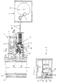
- 1 denotes a locking device according to the invention, the housing 2 of which is fastened to the steering column 3 of a motor vehicle.
- the locking device 1 is connected via a Bowden cable 4 to a starter unit 5, of which only a control cam 6 which can be actuated by the respective ignition key and a lever 7 connected to the Bowden cable 4 and guided by the control cam 6 are shown for reasons of clarity.
- the locking device 1 contains a locking element 8, which consists of a locking pin 10 facing the steering spindle 9 of the motor vehicle and a driver part 11, the locking pin 10 being supported by a spring 12 on the driver part 11 and being guided through this part.
- a rocker-shaped pivot lever also referred to below as a rocker
- the rocker 14 points to the Bowden cable 4 facing side has a recess 15 into which a cam 16 of a sliding piece 17 connected to the Bowden cable 4 engages as soon as the rocker 14 is pivoted out of the locking position shown in FIG.
- the rocker 14 In the locked position, the rocker 14 is held by a locking member 18, which can be moved by an electromagnet (solenoid) 19 (Fig.2).
- the rocker 14 also has a guide bevel 20, the function of which will be explained below.
- 21 and 22 also denote two microswitches which monitor the respective end positions of the rocker 14 or the respective position of the driver 11 via corresponding switching cams 23, 24 and whose function is also explained below.
- the driver 11 When the ignition key is removed, the driver 11 is pushed into the left end position (Fig. 1).
- the locking pin 10 is immersed in the recess 25 provided for this purpose in the steering spindle 9.
- Both microswitches 21, 22 are not actuated in this starting position.
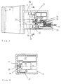
- the locking member 18 is extended and blocks both the rocker 14 in its position and the driver 11 in its position, the locking member engaging in a recess 26 of the driver (Fig.2).
- the driver 11 After a fixed stroke (of e.g. 8 mm), the driver 11 passes over the microswitch 22 and enables the vehicle to be started. At the same time, the electromagnet 19 is controlled by this signal. By extending the locking member 18, this secures the position of the rocker 14 in the driving position of the driver 11 and the locking bolt 10 by the locking member 18 engaging in a corresponding recess 28 of the rocker 14 and the locking bolt 10.
- the locking process is initiated by turning back the key and thus the control cam 6.
- the driver 11 can only be moved after the ignition key has been removed. This is realized in that the electromagnet 19 blocks the driver 11, although the Bowden cable 4 has already been relieved in the starter unit 5.
- the required pulse is triggered when the key is removed from the starter unit 5.
- the unit consisting of locking bolt 10, driver 11 and rocker 14, can perform the shift into the locked position.
- the microswitch 22 is run over and controls the electromagnet 19 on. The latter moves the locking member 18, which rotates the rocker 14 into its second end position via the guide bevel 20 provided on it and thus disengages the sliding piece 17 of the Bowden cable 4.
- the microswitch 21 is also relieved.
- the locking pin 10 If, due to an unfavorable steering wheel position, the locking pin 10 is not immersed in the recess 25 of the steering spindle 9 provided for this purpose during the locking process, then it deflects into an opening 29 provided in the driver 11 (FIG. 3). When the steering wheel moves later, the locking pin 10 jumps into the recess 25 due to the pressure of the spring 12. This prevents a blocking situation during the locking process.
- the solenoid can work spring-loaded, but must then always be energized in the extended position.
- it can also be designed as a bistable component with two defined end positions.
- a conventional mechanical key withdrawal lock can also be used. This eliminates the radial load on the locking member 18 during the lifting movement.
Landscapes
- Engineering & Computer Science (AREA)
- Mechanical Engineering (AREA)
- Lock And Its Accessories (AREA)
Applications Claiming Priority (2)
| Application Number | Priority Date | Filing Date | Title |
|---|---|---|---|
| DE19509097 | 1995-03-16 | ||
| DE19509097A DE19509097C1 (de) | 1995-03-16 | 1995-03-16 | Verriegelungsvorrichtung für Kraftfahrzeuge |
Publications (3)
| Publication Number | Publication Date |
|---|---|
| EP0732241A2 true EP0732241A2 (fr) | 1996-09-18 |
| EP0732241A3 EP0732241A3 (fr) | 1997-12-29 |
| EP0732241B1 EP0732241B1 (fr) | 2000-05-10 |
Family
ID=7756587
Family Applications (1)
| Application Number | Title | Priority Date | Filing Date |
|---|---|---|---|
| EP96100408A Expired - Lifetime EP0732241B1 (fr) | 1995-03-16 | 1996-01-12 | Dispositif de verrouillage pour véhicules |
Country Status (3)
| Country | Link |
|---|---|
| EP (1) | EP0732241B1 (fr) |
| DE (2) | DE19509097C1 (fr) |
| ES (1) | ES2148597T3 (fr) |
Cited By (2)
| Publication number | Priority date | Publication date | Assignee | Title |
|---|---|---|---|---|
| EP1359069A4 (fr) * | 2001-02-09 | 2005-06-08 | Tokai Rika Co Ltd | Mecanisme electronique de verrouillage de direction |
| DE102011108464A1 (de) | 2011-07-23 | 2013-01-24 | Volkswagen Aktiengesellschaft | Bistabiler Hubmagnet für Lenkungsverriegelungen |
Families Citing this family (2)
| Publication number | Priority date | Publication date | Assignee | Title |
|---|---|---|---|---|
| FR2748710B1 (fr) * | 1996-05-17 | 1998-06-26 | Valeo Securite Habitacle | Antivol motorise pour la direction d'un vehicule automobile comportant un commutateur perfectionne |
| DE10233511A1 (de) * | 2002-07-23 | 2004-04-22 | Huf Hülsbeck & Fürst Gmbh & Co. Kg | Schließsystem für Motorfahrzeuge |
Family Cites Families (2)
| Publication number | Priority date | Publication date | Assignee | Title |
|---|---|---|---|---|
| DE3739172C1 (en) * | 1987-11-19 | 1989-02-09 | Daimler Benz Ag | Locking system for motor vehicles |
| US4907427A (en) * | 1988-12-27 | 1990-03-13 | Armstrong Ennels D | Steering wheel shaft lock assembly |
-
1995
- 1995-03-16 DE DE19509097A patent/DE19509097C1/de not_active Expired - Lifetime
-
1996
- 1996-01-12 EP EP96100408A patent/EP0732241B1/fr not_active Expired - Lifetime
- 1996-01-12 ES ES96100408T patent/ES2148597T3/es not_active Expired - Lifetime
- 1996-01-12 DE DE59605156T patent/DE59605156D1/de not_active Expired - Lifetime
Cited By (2)
| Publication number | Priority date | Publication date | Assignee | Title |
|---|---|---|---|---|
| EP1359069A4 (fr) * | 2001-02-09 | 2005-06-08 | Tokai Rika Co Ltd | Mecanisme electronique de verrouillage de direction |
| DE102011108464A1 (de) | 2011-07-23 | 2013-01-24 | Volkswagen Aktiengesellschaft | Bistabiler Hubmagnet für Lenkungsverriegelungen |
Also Published As
| Publication number | Publication date |
|---|---|
| DE19509097C1 (de) | 1996-04-04 |
| ES2148597T3 (es) | 2000-10-16 |
| EP0732241B1 (fr) | 2000-05-10 |
| EP0732241A3 (fr) | 1997-12-29 |
| DE59605156D1 (de) | 2000-06-15 |
Similar Documents
| Publication | Publication Date | Title |
|---|---|---|
| DE69704587T2 (de) | Autotürschloss | |
| DE69922373T2 (de) | Verschlussvorrichtung und haubenschloss für ein fahrzeug mit einer derartigen verschlussvorrichtung | |
| EP0972899A2 (fr) | Dispositif de verrouillage, notamment pour une porte de véhicule automobile | |
| DE19949119A1 (de) | Vorrichtung zur Verriegelung eines bewegbaren an einem Kraftfahrzeug angeordneten Teiles | |
| DE4108561C2 (fr) | ||
| DE69408741T2 (de) | Türverriegelungssystem für Fahrzeuge | |
| DE60102979T2 (de) | Lenksäulendiebstahlsicherung mit Mittel zur Bolzenverriegelung | |
| DE19621326C1 (de) | Kraftfahrzeug-Lenkungsverriegelung | |
| EP0887240B1 (fr) | Dispositif de verrouillage pour véhicule automobile | |
| DE4325693C2 (de) | Türschließeinrichtung | |
| EP0999968A2 (fr) | Blocage de volant de direction sur une automobile | |
| EP0992393A2 (fr) | Dispositif pour verrouiller des dossiers rabattables partiellement de sièges arrières de véhicules automobiles | |
| DE1956163A1 (de) | Diebstahlsicherung fuer Kraftfahrzeuge | |
| DE19653860C1 (de) | Schließsystem für Kraftfahrzeuge | |
| EP0721869B1 (fr) | Dispositif de verrouillage pour véhicules | |
| EP0732241B1 (fr) | Dispositif de verrouillage pour véhicules | |
| DE3344411A1 (de) | Lenk- und zuendschloss fuer kraftfahrzeuge | |
| DE3316793A1 (de) | Kombination einer zentral-verriegelungs-anlage mit einer diebstahl-warnanlage | |
| EP0791707B1 (fr) | Serrure pour véhicule automobile | |
| DE8802327U1 (de) | Lenkschloß für Kraftfahrzeuge mit automatischem Getriebe | |
| DE3737700C2 (fr) | ||
| DE3521570C2 (de) | Mit einer Fernbedienungseinrichtung ausgerüstete Zentralverriegelungsanlage für ein Kraftfahrzeug | |
| EP0833023A2 (fr) | Serrure cylindrique avec une embrayage de surcharge | |
| DE4416864C1 (de) | Vorrichtung mit einem Wählhebel für Kraftfahrzeug-Automatikgetriebe | |
| DE10230586B4 (de) | Kraftfahrzeugtürverschluss |
Legal Events
| Date | Code | Title | Description |
|---|---|---|---|
| PUAI | Public reference made under article 153(3) epc to a published international application that has entered the european phase |
Free format text: ORIGINAL CODE: 0009012 |
|
| AK | Designated contracting states |
Kind code of ref document: A2 Designated state(s): DE ES FR GB IT SE |
|
| RAP1 | Party data changed (applicant data changed or rights of an application transferred) |
Owner name: VALEO GMBH & CO SCHLIESSSYSTEME KG |
|
| PUAL | Search report despatched |
Free format text: ORIGINAL CODE: 0009013 |
|
| AK | Designated contracting states |
Kind code of ref document: A3 Designated state(s): DE ES FR GB IT SE |
|
| 17P | Request for examination filed |
Effective date: 19971126 |
|
| GRAG | Despatch of communication of intention to grant |
Free format text: ORIGINAL CODE: EPIDOS AGRA |
|
| GRAG | Despatch of communication of intention to grant |
Free format text: ORIGINAL CODE: EPIDOS AGRA |
|
| GRAH | Despatch of communication of intention to grant a patent |
Free format text: ORIGINAL CODE: EPIDOS IGRA |
|
| 17Q | First examination report despatched |
Effective date: 19990601 |
|
| GRAH | Despatch of communication of intention to grant a patent |
Free format text: ORIGINAL CODE: EPIDOS IGRA |
|
| RIN1 | Information on inventor provided before grant (corrected) |
Inventor name: KALESSE, MICHAEL Inventor name: RICHTER, MARTIN Inventor name: LIEB, KURT |
|
| GRAA | (expected) grant |
Free format text: ORIGINAL CODE: 0009210 |
|
| AK | Designated contracting states |
Kind code of ref document: B1 Designated state(s): DE ES FR GB IT SE |
|
| GBT | Gb: translation of ep patent filed (gb section 77(6)(a)/1977) |
Effective date: 20000510 |
|
| REF | Corresponds to: |
Ref document number: 59605156 Country of ref document: DE Date of ref document: 20000615 |
|
| ET | Fr: translation filed | ||
| ITF | It: translation for a ep patent filed | ||
| REG | Reference to a national code |
Ref country code: ES Ref legal event code: FG2A Ref document number: 2148597 Country of ref document: ES Kind code of ref document: T3 |
|
| PLBE | No opposition filed within time limit |
Free format text: ORIGINAL CODE: 0009261 |
|
| STAA | Information on the status of an ep patent application or granted ep patent |
Free format text: STATUS: NO OPPOSITION FILED WITHIN TIME LIMIT |
|
| 26N | No opposition filed | ||
| REG | Reference to a national code |
Ref country code: GB Ref legal event code: IF02 |
|
| PGFP | Annual fee paid to national office [announced via postgrant information from national office to epo] |
Ref country code: SE Payment date: 20140110 Year of fee payment: 19 Ref country code: DE Payment date: 20140107 Year of fee payment: 19 |
|
| PGFP | Annual fee paid to national office [announced via postgrant information from national office to epo] |
Ref country code: IT Payment date: 20140116 Year of fee payment: 19 Ref country code: ES Payment date: 20140123 Year of fee payment: 19 Ref country code: FR Payment date: 20140131 Year of fee payment: 19 |
|
| PGFP | Annual fee paid to national office [announced via postgrant information from national office to epo] |
Ref country code: GB Payment date: 20140116 Year of fee payment: 19 |
|
| REG | Reference to a national code |
Ref country code: DE Ref legal event code: R119 Ref document number: 59605156 Country of ref document: DE |
|
| REG | Reference to a national code |
Ref country code: SE Ref legal event code: EUG |
|
| GBPC | Gb: european patent ceased through non-payment of renewal fee |
Effective date: 20150112 |
|
| PG25 | Lapsed in a contracting state [announced via postgrant information from national office to epo] |
Ref country code: DE Free format text: LAPSE BECAUSE OF NON-PAYMENT OF DUE FEES Effective date: 20150801 Ref country code: GB Free format text: LAPSE BECAUSE OF NON-PAYMENT OF DUE FEES Effective date: 20150112 |
|
| REG | Reference to a national code |
Ref country code: FR Ref legal event code: ST Effective date: 20150930 |
|
| PG25 | Lapsed in a contracting state [announced via postgrant information from national office to epo] |
Ref country code: FR Free format text: LAPSE BECAUSE OF NON-PAYMENT OF DUE FEES Effective date: 20150202 Ref country code: SE Free format text: LAPSE BECAUSE OF NON-PAYMENT OF DUE FEES Effective date: 20150113 |
|
| PG25 | Lapsed in a contracting state [announced via postgrant information from national office to epo] |
Ref country code: IT Free format text: LAPSE BECAUSE OF NON-PAYMENT OF DUE FEES Effective date: 20150112 |
|
| REG | Reference to a national code |
Ref country code: ES Ref legal event code: FD2A Effective date: 20160226 |
|
| PG25 | Lapsed in a contracting state [announced via postgrant information from national office to epo] |
Ref country code: ES Free format text: LAPSE BECAUSE OF NON-PAYMENT OF DUE FEES Effective date: 20150113 |