EP0732293B1 - Procédé pour optimiser le rendement d'exploitation d'une machine de pliage - Google Patents
Procédé pour optimiser le rendement d'exploitation d'une machine de pliage Download PDFInfo
- Publication number
- EP0732293B1 EP0732293B1 EP19960104141 EP96104141A EP0732293B1 EP 0732293 B1 EP0732293 B1 EP 0732293B1 EP 19960104141 EP19960104141 EP 19960104141 EP 96104141 A EP96104141 A EP 96104141A EP 0732293 B1 EP0732293 B1 EP 0732293B1
- Authority
- EP
- European Patent Office
- Prior art keywords
- sheet
- folding
- pulse
- detectors
- Prior art date
- Legal status (The legal status is an assumption and is not a legal conclusion. Google has not performed a legal analysis and makes no representation as to the accuracy of the status listed.)
- Expired - Lifetime
Links
- 238000000034 method Methods 0.000 title claims description 21
- 238000005457 optimization Methods 0.000 title description 2
- 238000004519 manufacturing process Methods 0.000 claims description 5
- 230000001105 regulatory effect Effects 0.000 claims description 5
- 238000011144 upstream manufacturing Methods 0.000 claims description 4
- 238000012935 Averaging Methods 0.000 claims 1
- 230000007246 mechanism Effects 0.000 description 6
- 230000008569 process Effects 0.000 description 5
- 230000032258 transport Effects 0.000 description 3
- 235000008659 Pteris ensiformis Nutrition 0.000 description 2
- 240000001625 Pteris ensiformis Species 0.000 description 2
- 230000006870 function Effects 0.000 description 2
- 230000001960 triggered effect Effects 0.000 description 2
- 230000008901 benefit Effects 0.000 description 1
- 230000008878 coupling Effects 0.000 description 1
- 238000010168 coupling process Methods 0.000 description 1
- 238000005859 coupling reaction Methods 0.000 description 1
- 230000001419 dependent effect Effects 0.000 description 1
- 238000001514 detection method Methods 0.000 description 1
- 230000008034 disappearance Effects 0.000 description 1
- 230000007257 malfunction Effects 0.000 description 1
- 230000002123 temporal effect Effects 0.000 description 1
Images



Classifications
-
- B—PERFORMING OPERATIONS; TRANSPORTING
- B65—CONVEYING; PACKING; STORING; HANDLING THIN OR FILAMENTARY MATERIAL
- B65H—HANDLING THIN OR FILAMENTARY MATERIAL, e.g. SHEETS, WEBS, CABLES
- B65H45/00—Folding thin material
-
- B—PERFORMING OPERATIONS; TRANSPORTING
- B65—CONVEYING; PACKING; STORING; HANDLING THIN OR FILAMENTARY MATERIAL
- B65H—HANDLING THIN OR FILAMENTARY MATERIAL, e.g. SHEETS, WEBS, CABLES
- B65H2511/00—Dimensions; Position; Numbers; Identification; Occurrences
- B65H2511/20—Location in space
- B65H2511/22—Distance
-
- B—PERFORMING OPERATIONS; TRANSPORTING
- B65—CONVEYING; PACKING; STORING; HANDLING THIN OR FILAMENTARY MATERIAL
- B65H—HANDLING THIN OR FILAMENTARY MATERIAL, e.g. SHEETS, WEBS, CABLES
- B65H2511/00—Dimensions; Position; Numbers; Identification; Occurrences
- B65H2511/50—Occurence
- B65H2511/51—Presence
- B65H2511/514—Particular portion of element
-
- B—PERFORMING OPERATIONS; TRANSPORTING
- B65—CONVEYING; PACKING; STORING; HANDLING THIN OR FILAMENTARY MATERIAL
- B65H—HANDLING THIN OR FILAMENTARY MATERIAL, e.g. SHEETS, WEBS, CABLES
- B65H2513/00—Dynamic entities; Timing aspects
- B65H2513/50—Timing
Definitions
- the invention relates to a method for optimizing the Operating performance of a folding machine with a sheet feeder and several successive folding stations by means of a central control device in which signals from sheet detectors processed in different places the folding machine arranged along the sheet path are.
- the transport distance should optimize the folding performance be as small as possible between two folded sheets.
- the minimum sheet spacing must, however, be so large that a folded sheet completely from the sheet entry zone of a Folding machine has disappeared before the next sheet is in this zone can enter.
- the object of the invention is to develop a method the sheet clearance required on the folding machine determined and dependent on the respective folding unit and the sheet geometry automatically on the suction wheel adjusts to the operating performance of the folding machine optimize.
- the invention is based on the consideration that for the setting the minimum arc distance is a learning process or a scheme can be used when the folding machine has a central control device in which Signals from arc detectors are processed on different critical points of the folding machine along the Sheet passage are arranged, especially in the area the sheet inlet of the respective folding units.
- the method is characterized in that that a given one Minimum distance between two pulse edges Sheet detectors, the first of which is the trailing edge of a preceding sheet at the sheet inlet of a folding station and the second represents the leading edge of the following sheet, is not fallen below, the first pulse edge being supplied by an arc detector, which is provided by the Time of sheet entry until the sheet disappears delivers the same signal level from the fold zone.
- the two pulse edges from an arc detector delivered at the sheet inlet of the sword folding unit which in one predetermined distance behind an upstream to which Arc length adjustable arc detector is arranged, the Pulse signal when the trailing edge of a sheet is detected triggers the drive of the folding blade for a folding process.
- This upstream sheet detector is on the rear edge an arch aligned with the stop of the sword folding mechanism set.
- the two pulse edges from a pair of arc detectors on the Pocket folding unit delivered the second pulse edge of the The leading edge of a sheet at the sheet inlet and the first pulse edge the rear edge of one emerging from a folding pocket Arc corresponds.
- the different Folders each have an associated minimum distance between two pulse edges of the arc detectors on given pulse signals given each sheet inlet and the distance between the trigger pulses for the sheet feeder regulated so that none of the specified minimum distances is undercut.
- Fig. 1a is a in the folding machine Shrinked sheet shown at the start of folding, which in Fig. 1b is finally folded. Faults during folding operation it happens when the following sheet shown in Fig. 1b comes to arrives early in the folding machine when the leading one Sheet has not yet been folded. The folded one leading sheet must be completely out of the sheet entry zone the folding machine must have disappeared before the subsequent one Arch can enter this zone.
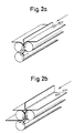
- FIGS. 2a and 2b A knife.
- Fig. 2a shows the start of folding a straight 2b the folded end of this sheet, when he has left the sheet entry zone, so that a subsequent sheet can enter.
- Fig. 3 is a combination folding machine consisting of a pocket folder 12 and an adjoining one Sword folding mechanism 14 shown.
- suction wheel 16 as part of a sheet feeder 20 transports sheets of paper from a tray to one Conveyor line that includes an alignment table.
- a Central control device 10 of a digital control system becomes a certain suction cycle Y1 for the suction wheel 16 established.
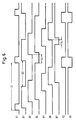
- Sheet detectors B1, B2, B4 to B7 are on different positions in the combination folding machine arranged and are covered during the sheet passage and deliver the signal level on and during the Pause the signal level off, as is shown in FIG. 6 is described in more detail.
- control device 10 of the digital control system the entire sensors and actuators of the folding machine are linked.
- the Control the signals of the sheet detectors B1, B2, B4, B5, B6, B7 and the incremental gear B3 and controls the Suction cycle Y1 of the suction wheel 16 and the sword cycle Y2, Y3.
- the bow detector B1 is in the immediate vicinity of the Suction wheel 16, the sheet detector B2 at the sheet inlet of the Pocket folder 12 and the sheet detector B4 at the pocket inlet a first folding pocket.
- the bow detector B5 is on Arch outlet of the pocket folding unit 12 arranged.
- the bow detector 1.84 leads from the time of the sheet entry to When the signal level disappears from the fold zone On. Only when the arc detector B4 turns the signal level off leads, the next sheet may go into the folding zone of the pocket folding unit 12 break in.
- Sheet detectors B6 and B7 are on a format adjustable Holder in a subsequent to the pocket folder 12 Sword folder 14 attached.
- the holder (see Fig. 5) is set so that the rear edge of the stop of the sword folding unit 14 transported the folding sheet Do not cover sheet detector B6 anymore.
- the location of the arc detectors B2, B4 and B5 is more accurate in Fig. 4 and the location the sheet detectors B6, B7 and the holder is more precise in Fig. 5 shown.
- After the sheet entry is with the falling Signal of the arc detector B6 acting as a signal generator Heavy stroke triggered.
- the arc detector B7 leads from the time of the sheet entry until the time of disappearance the signal level on from the folding zone. Only when the sensor B7 leads to the signal level Off, the next arc can be in the Run in the folding zone of the sword folding unit 14.
- the suction cycle control is adjusted to the correct pitch, so that the minimum Bow spacing on pocket and sword folding mechanism 12, 14 maintained becomes. There is a percentage security surcharge added to the measured minimum distance.
- the central control device 10 calculates by means of the Waveforms of the arc detectors B2, B4, B5, B6, B7 and the signals of the incremental encoder B3 the correct arc distance on the suction wheel 16.
- the corresponding waveforms the arc detectors and incremental encoders are in Fig. 6 shown for a specific sheet format and a fold type.
- S6 is the suction cycle setting determined by the learning curve, which are normally maintained during production is designated Y1.
- S1 is the suction cycle period. With B1, B2 and B4 to B7 the signal levels are the corresponding arc detectors are shown. Designated S2 the arc distance on the suction wheel, S3 the arc distance in the Folding pocket of the pocket folding unit 12 and S4 the sheet spacing the switching states on the 14. Y2 and Y3 sword folding unit a sword clutch or a sword brake, which in Fig. 3 are not shown explicitly again.
- the operating performance of the folding machine shown in Fig. 3 is optimized in that the signals from the arc detectors B1, B2 and B4 to B7 and the incremental encoder B3 from the Control device 10 are processed as follows: the temporal distance between the fed to the sheet feeder 20 Trigger pulses will be at the lowest possible value regulated, at which a predetermined minimum distance between two pulse edges of the arc detectors B2 and B4 are not is undercut.
- the first pulse edge is the Trailing edge of a preceding sheet at sheet inlet 11 of the pocket folder 12 and the second pulse edge Leading edge of the following sheet.
- the sheet detector B7 at the sheet inlet of the sword folding unit 14 provides a pulse, the edge of which Is assigned to the trailing edge of a preceding sheet.
- the Bow detector B6 in turn provides a pulse with one Flank, which is the leading edge of a subsequent sheet assigned. From the corresponding difference we can the sheet spacing S4 (see FIG. 6) on the sword folding mechanism 14 determine.
- the pulse signal upon detection of the trailing edge of the preceding arc releases, as clearly shown in FIG. 5 is recognizable, the drive of the folding blade for a folding process from the sword coupling by means of the signal Y2 in the on state and the sword brake by means of the Signal Y3 is transferred to the off state. Because of this The process becomes the operating performance of the sword folding unit 14 and thus also optimized the entire combination folding machine, because it is impossible that the folding sword too is triggered at the wrong time and the following one Sheet enters the sword folding mechanism 14 too early.
- Another optimization of operational performance is the actual minimum distances during ongoing production to be measured and the arc distance by determining the trend S2 on suction wheel 16 to reduce or increase.
- the determined sheet lengths are used for sheet throughput control used.
- the bow detectors B2 and B4 are also used as a control of the complete sheet entry into the folding pocket.
- the signals emitted by the arc detectors B2 and B4 can in the control device 10 for two further functions are processed:
- a sheet that does not run to the pocket stop will not properly folded and leads to production problems.
- the path of the incoming and outgoing sheet saved and as a reference value for the Folded sheets used in production.
- the advantage of Pocket check is a folded sheet early is recognized and the folder drive is quickly switched off can be.
Landscapes
- Folding Of Thin Sheet-Like Materials, Special Discharging Devices, And Others (AREA)
Claims (7)
- Procédé portant sur l'optimisation de performance d'une plieuse avec margeur (20) et de plusieurs stations de pliage successives à l'aide d'un système de commande (10) central qui traite les signaux déclenchés par des détecteurs de feuilles (B1, B2, B4 à B7) installés à divers endroits de la plieuse le long du passage des feuilles, procédé dans lequel l'intervalle entre les impulsions déclenchant le margeur (20) correspond à la distance minimum entre deux feuilles après que cet intervalle ait été fixé à une valeur minimum, cette valeur minimum de l'intervalle étant déterminée à l'aide d'un procédé spécial caractérisé en ce qu'une distance minimum prédéterminée entre deux flancs d'impulsions déclenchés par les détecteurs de feuilles (B2, B4, B6, B7) ne descend pas sous une limite définie, le premier flanc d'impulsions représentant le bord arrière d'une feuille précédente à l'entrée des feuilles (11) d'une station de pliage, le second le bord avant de la feuille suivante, le premier flanc d'impulsions étant livré par un détecteur de feuilles (B4, B7) qui fournit une signalisation au niveau restant constant à partir du moment de l'entrée de la feuille jusqu' au moment de la sortie de la feuille de la zone de pliage.
- Procédé selon la revendication 1 caractérisé en ce que le deuxième flanc d'impulsions est déclenché par un détecteur de feuilles (B7) qui est situé à l'entrée d'un groupe de pliage à couteau (14) et installé à une distance prédéterminée derrière un autre détecteur de feuilles (B6) situé plus en avant et réglable selon la longueur de la feuille et dont l'impulsion déclenchée au moment du passage du bord arrière d'une feuille déclenche l'entraínement de la lame de pliage pour un processus de pliage.
- Procédé selon la revendication 2 caractérisé en ce que le détecteur de feuilles (6) situé plus en avant est aligné avec le bord arrière d'une feuille ajustée à la butée du groupe de pliage à couteau (14).
- Procédé selon la revendication 1 caractérisé en ce que les deux flancs d'impulsions sont déclenchés par une paire de détecteurs de feuilles (B2, B4) situés à un groupe de pliage à poches (12), procédé dans lequel le second flanc d'impulsions correspond au bord avant d'une feuille à l'entrée (11) des feuilles et le premier flanc d'impulsions correspond au bord arrière d'une feuille précédente sortant d'une poche de pliage.
- Procédé selon l'une des revendications mentionnées ci-dessus caractérisé en ce que pour plusieurs stations de pliage une distance minimum respective est définie entre deux flancs d'impulsions des signaux déclenchés par les détecteurs de feuilles (B1, B2, B4 à B7) à l'entrée (11) respective des feuilles et que la distance entre les impulsions déclenchant le margeur de feuilles (20) est réglée de telle sorte qu'elle ne descende en dessous des distances minimum prédéterminées.
- Procédé selon l'une des revendications mentionnées ci-dessus caractérisé en ce que les variations temporelles dans le fonctionnement des flancs d'impulsions sont nivelées par la détermination d'une valeur moyenne.
- Procédé selon l'une des revendications mentionnées ci-dessus caractérisé en ce qu'une feuille isolée est utilisée comme feuille d'essai et passe toutes les stations de pliage avant le début de la production, que la longueur de la feuille est déterminée selon les signaux déclenchés par les détecteurs de feuilles (B1, B2, B4 à B7) et que la vitesse du passage des feuilles de la plieuse est fixée à une valeur maximum telle que ni limite prédéterminée de la vitesse du passage des feuilles ni valeur limite prédéterminée du temps de cadence du margeur (20) résultant de la longueur de la feuille, de la distance entre deux feuilles et de la vitesse du passage des feuilles ne sont dépassées.
Applications Claiming Priority (4)
| Application Number | Priority Date | Filing Date | Title |
|---|---|---|---|
| DE19509323 | 1995-03-15 | ||
| DE19509323 | 1995-03-15 | ||
| DE19516437 | 1995-05-04 | ||
| DE19516437A DE19516437B4 (de) | 1995-03-15 | 1995-05-04 | Verfahren zur Optimierung der Betriebsleistung einer Falzmaschine |
Publications (3)
| Publication Number | Publication Date |
|---|---|
| EP0732293A2 EP0732293A2 (fr) | 1996-09-18 |
| EP0732293A3 EP0732293A3 (fr) | 1997-07-23 |
| EP0732293B1 true EP0732293B1 (fr) | 2002-01-30 |
Family
ID=26013383
Family Applications (1)
| Application Number | Title | Priority Date | Filing Date |
|---|---|---|---|
| EP19960104141 Expired - Lifetime EP0732293B1 (fr) | 1995-03-15 | 1996-03-15 | Procédé pour optimiser le rendement d'exploitation d'une machine de pliage |
Country Status (2)
| Country | Link |
|---|---|
| EP (1) | EP0732293B1 (fr) |
| PT (1) | PT732293E (fr) |
Cited By (2)
| Publication number | Priority date | Publication date | Assignee | Title |
|---|---|---|---|---|
| DE102016203043A1 (de) | 2016-02-26 | 2017-08-31 | Heidelberger Druckmaschinen Ag | Verfahren zum Falzen von Bogen und Falzmaschine |
| WO2023194874A1 (fr) * | 2022-04-05 | 2023-10-12 | Dandekar Sanjay Madhav | Système de fonctionnement d'une machine de pliage de papier |
Families Citing this family (5)
| Publication number | Priority date | Publication date | Assignee | Title |
|---|---|---|---|---|
| DE19747997A1 (de) * | 1997-10-30 | 1999-05-12 | Stahl Gmbh & Co Maschf | Taschenfalzwerk und Verfahren zur Registerregelung eines Taschenfalzwerks |
| US6440049B1 (en) * | 1998-02-02 | 2002-08-27 | Heidelberger Druckmaschinen Ag | Folder with early warning jam detection system and related method |
| DE19860070A1 (de) | 1998-12-23 | 2000-06-29 | Stahl Gmbh & Co Maschf | Taschenfalzwerk und Verfahren zur Registerregelung eines Taschenfalzwerks |
| DE10059271A1 (de) * | 2000-11-29 | 2002-06-06 | Heidelberger Druckmasch Ag | Falzschwertsteuerung |
| DE102006021901B4 (de) * | 2006-05-11 | 2008-08-21 | Koenig & Bauer Aktiengesellschaft | Verfahren zum Längsfalzen von zu falzenden Produkten |
Family Cites Families (3)
| Publication number | Priority date | Publication date | Assignee | Title |
|---|---|---|---|---|
| DE3935056C2 (de) * | 1989-10-20 | 1996-07-11 | Stahl Gmbh & Co Maschf | Verfahren zur Kontrolle des Bogendurchlaufs in einer Falzmaschine und Vorrichtung zur Durchführung des Verfahrens |
| DE4013401A1 (de) * | 1990-04-26 | 1991-10-31 | Binder & Co Masch Oppenweiler | Verfahren zum einrichten und steuern einer falzmaschine |
| DE4315095A1 (de) * | 1993-05-06 | 1994-11-10 | Stahl Gmbh & Co Maschf | Verfahren zum Betreiben einer Falzmaschine |
-
1996
- 1996-03-15 PT PT96104141T patent/PT732293E/pt unknown
- 1996-03-15 EP EP19960104141 patent/EP0732293B1/fr not_active Expired - Lifetime
Cited By (3)
| Publication number | Priority date | Publication date | Assignee | Title |
|---|---|---|---|---|
| DE102016203043A1 (de) | 2016-02-26 | 2017-08-31 | Heidelberger Druckmaschinen Ag | Verfahren zum Falzen von Bogen und Falzmaschine |
| DE102016203043B4 (de) | 2016-02-26 | 2018-05-09 | Heidelberger Druckmaschinen Ag | Verfahren zum Falzen von Bogen und Falzmaschine |
| WO2023194874A1 (fr) * | 2022-04-05 | 2023-10-12 | Dandekar Sanjay Madhav | Système de fonctionnement d'une machine de pliage de papier |
Also Published As
| Publication number | Publication date |
|---|---|
| EP0732293A3 (fr) | 1997-07-23 |
| PT732293E (pt) | 2002-07-31 |
| EP0732293A2 (fr) | 1996-09-18 |
Similar Documents
| Publication | Publication Date | Title |
|---|---|---|
| DE3010793C2 (de) | Vorrichtung zum Sortieren von Banknoten unterschiedlicher Größe und Wertung | |
| DE3319247C2 (de) | Verfahren und Vorrichtung zum Fördern von Blattlagen zu einer Weiterverarbeitungsmaschine | |
| DE2118587C3 (de) | Einrichtung zum gegenseitigen Anpassen der Fördergeschwindigkeiten zweier Förderer | |
| EP0873273B1 (fr) | Plieuse a dispositif de separation de signatures | |
| DE3301722C2 (de) | Verfahren und Vorrichtung zur paßgerechten Zuführung von Bogen an bogenverarbeitenden Maschinen | |
| EP1281653A2 (fr) | Dispositif pour le traitement des supports d'impression sous forme de feuilles | |
| EP0732293B1 (fr) | Procédé pour optimiser le rendement d'exploitation d'une machine de pliage | |
| EP1421022B1 (fr) | Procede et dispositif de detection d'un enlevement en double | |
| EP0453909B1 (fr) | Procédé pour le positionnement et le réglage d'une plieuse | |
| EP1013589B1 (fr) | Plieuse à poches et procédé de contrôle du registre dans une plieuse à poches | |
| EP1811851B1 (fr) | Procede et dispositif pour decouper des saucisses | |
| DE3935056C2 (de) | Verfahren zur Kontrolle des Bogendurchlaufs in einer Falzmaschine und Vorrichtung zur Durchführung des Verfahrens | |
| EP2695741B1 (fr) | Machine de coudre | |
| DE19516437B4 (de) | Verfahren zur Optimierung der Betriebsleistung einer Falzmaschine | |
| DE68912096T2 (de) | Kopiergerät. | |
| EP1588965B1 (fr) | Méthode pour commander la position d'une feuille dans une plieuse | |
| DD154866A3 (de) | Einrichtung zur steuerung einer druckmaschine | |
| DE19506463C2 (de) | Stauüberwachungseinrichtung für eine Transportvorrichtung für Papier, insbesondere für eine Papierbahn | |
| DE2051065A1 (de) | Überwachungseinrichtung auf Registerhaltigkeit von bedruckten Bögen | |
| EP2492107B1 (fr) | Couseuse au fil textile | |
| EP1854753B1 (fr) | Appareil de pliage et procédé de pliage en longueur de produits ayant une largeur variable | |
| DE69514024T2 (de) | Blattfördervorrichtung | |
| DE10140101B4 (de) | Blattgutstapelvorrichtung | |
| DE2747598C2 (de) | Einrichtung zur Regelung der Arbeitsgeschwindigkeit mehrerer hintereinandergeschalteter Flaschenbehandlungsmaschinen | |
| DE3320381C2 (fr) |
Legal Events
| Date | Code | Title | Description |
|---|---|---|---|
| PUAI | Public reference made under article 153(3) epc to a published international application that has entered the european phase |
Free format text: ORIGINAL CODE: 0009012 |
|
| AK | Designated contracting states |
Kind code of ref document: A2 Designated state(s): CH DE IT LI PT |
|
| PUAL | Search report despatched |
Free format text: ORIGINAL CODE: 0009013 |
|
| AK | Designated contracting states |
Kind code of ref document: A3 Designated state(s): CH DE IT LI PT |
|
| 17P | Request for examination filed |
Effective date: 19970922 |
|
| 17Q | First examination report despatched |
Effective date: 19990628 |
|
| RAP1 | Party data changed (applicant data changed or rights of an application transferred) |
Owner name: HEIDELBERGER DRUCKMASCHINEN AKTIENGESELLSCHAFT |
|
| GRAG | Despatch of communication of intention to grant |
Free format text: ORIGINAL CODE: EPIDOS AGRA |
|
| GRAG | Despatch of communication of intention to grant |
Free format text: ORIGINAL CODE: EPIDOS AGRA |
|
| GRAG | Despatch of communication of intention to grant |
Free format text: ORIGINAL CODE: EPIDOS AGRA |
|
| GRAH | Despatch of communication of intention to grant a patent |
Free format text: ORIGINAL CODE: EPIDOS IGRA |
|
| GRAH | Despatch of communication of intention to grant a patent |
Free format text: ORIGINAL CODE: EPIDOS IGRA |
|
| GRAA | (expected) grant |
Free format text: ORIGINAL CODE: 0009210 |
|
| AK | Designated contracting states |
Kind code of ref document: B1 Designated state(s): CH DE IT LI PT |
|
| PG25 | Lapsed in a contracting state [announced via postgrant information from national office to epo] |
Ref country code: IT Free format text: LAPSE BECAUSE OF FAILURE TO SUBMIT A TRANSLATION OF THE DESCRIPTION OR TO PAY THE FEE WITHIN THE PRE;WARNING: LAPSES OF ITALIAN PATENTS WITH EFFECTIVE DATE BEFORE 2007 MAY HAVE OCCURRED AT ANY TIME BEFORE 2007. THE CORRECT EFFECTIVE DATE MAY BE DIFFERENT FROM THE ONE RECORDED.SCRIBED TIME-LIMIT Effective date: 20020130 |
|
| REG | Reference to a national code |
Ref country code: CH Ref legal event code: EP |
|
| REF | Corresponds to: |
Ref document number: 59608655 Country of ref document: DE Date of ref document: 20020314 |
|
| REG | Reference to a national code |
Ref country code: PT Ref legal event code: SC4A Free format text: AVAILABILITY OF NATIONAL TRANSLATION Effective date: 20020412 |
|
| PLBQ | Unpublished change to opponent data |
Free format text: ORIGINAL CODE: EPIDOS OPPO |
|
| PLBI | Opposition filed |
Free format text: ORIGINAL CODE: 0009260 |
|
| PLBF | Reply of patent proprietor to notice(s) of opposition |
Free format text: ORIGINAL CODE: EPIDOS OBSO |
|
| PLBQ | Unpublished change to opponent data |
Free format text: ORIGINAL CODE: EPIDOS OPPO |
|
| PLAB | Opposition data, opponent's data or that of the opponent's representative modified |
Free format text: ORIGINAL CODE: 0009299OPPO |
|
| PLBI | Opposition filed |
Free format text: ORIGINAL CODE: 0009260 |
|
| 26 | Opposition filed |
Opponent name: MASCHINENBAU OPPENWEILER BINDER GMBH & CO Effective date: 20021030 |
|
| 26 | Opposition filed |
Opponent name: MASCHINENBAU OPPENWEILER BINDER GMBH & CO Effective date: 20021030 |
|
| PLBF | Reply of patent proprietor to notice(s) of opposition |
Free format text: ORIGINAL CODE: EPIDOS OBSO |
|
| PLBF | Reply of patent proprietor to notice(s) of opposition |
Free format text: ORIGINAL CODE: EPIDOS OBSO |
|
| PLCK | Communication despatched that opposition was rejected |
Free format text: ORIGINAL CODE: EPIDOSNREJ1 |
|
| APBP | Date of receipt of notice of appeal recorded |
Free format text: ORIGINAL CODE: EPIDOSNNOA2O |
|
| APBQ | Date of receipt of statement of grounds of appeal recorded |
Free format text: ORIGINAL CODE: EPIDOSNNOA3O |
|
| APAA | Appeal reference recorded |
Free format text: ORIGINAL CODE: EPIDOS REFN |
|
| APBU | Appeal procedure closed |
Free format text: ORIGINAL CODE: EPIDOSNNOA9O |
|
| APAH | Appeal reference modified |
Free format text: ORIGINAL CODE: EPIDOSCREFNO |
|
| PLBN | Opposition rejected |
Free format text: ORIGINAL CODE: 0009273 |
|
| STAA | Information on the status of an ep patent application or granted ep patent |
Free format text: STATUS: OPPOSITION REJECTED |
|
| 27O | Opposition rejected |
Effective date: 20050601 |
|
| PGFP | Annual fee paid to national office [announced via postgrant information from national office to epo] |
Ref country code: CH Payment date: 20120425 Year of fee payment: 17 |
|
| PGFP | Annual fee paid to national office [announced via postgrant information from national office to epo] |
Ref country code: PT Payment date: 20130228 Year of fee payment: 18 |
|
| REG | Reference to a national code |
Ref country code: CH Ref legal event code: PL |
|
| PG25 | Lapsed in a contracting state [announced via postgrant information from national office to epo] |
Ref country code: CH Free format text: LAPSE BECAUSE OF NON-PAYMENT OF DUE FEES Effective date: 20130331 Ref country code: LI Free format text: LAPSE BECAUSE OF NON-PAYMENT OF DUE FEES Effective date: 20130331 |
|
| PGFP | Annual fee paid to national office [announced via postgrant information from national office to epo] |
Ref country code: DE Payment date: 20140331 Year of fee payment: 19 |
|
| REG | Reference to a national code |
Ref country code: PT Ref legal event code: MM4A Free format text: LAPSE DUE TO NON-PAYMENT OF FEES Effective date: 20140915 |
|
| PG25 | Lapsed in a contracting state [announced via postgrant information from national office to epo] |
Ref country code: PT Free format text: LAPSE BECAUSE OF NON-PAYMENT OF DUE FEES Effective date: 20140915 |
|
| REG | Reference to a national code |
Ref country code: DE Ref legal event code: R119 Ref document number: 59608655 Country of ref document: DE |
|
| PG25 | Lapsed in a contracting state [announced via postgrant information from national office to epo] |
Ref country code: DE Free format text: LAPSE BECAUSE OF NON-PAYMENT OF DUE FEES Effective date: 20151001 |