EP0732424A1 - Méthode et dispositif pour le traitement de produits en forme de plaque, e.p. des circuits imprimés - Google Patents
Méthode et dispositif pour le traitement de produits en forme de plaque, e.p. des circuits imprimés Download PDFInfo
- Publication number
- EP0732424A1 EP0732424A1 EP96103716A EP96103716A EP0732424A1 EP 0732424 A1 EP0732424 A1 EP 0732424A1 EP 96103716 A EP96103716 A EP 96103716A EP 96103716 A EP96103716 A EP 96103716A EP 0732424 A1 EP0732424 A1 EP 0732424A1
- Authority
- EP
- European Patent Office
- Prior art keywords
- treatment
- transport
- objects
- suction
- station
- Prior art date
- Legal status (The legal status is an assumption and is not a legal conclusion. Google has not performed a legal analysis and makes no representation as to the accuracy of the status listed.)
- Granted
Links
Images
Classifications
-
- C—CHEMISTRY; METALLURGY
- C23—COATING METALLIC MATERIAL; COATING MATERIAL WITH METALLIC MATERIAL; CHEMICAL SURFACE TREATMENT; DIFFUSION TREATMENT OF METALLIC MATERIAL; COATING BY VACUUM EVAPORATION, BY SPUTTERING, BY ION IMPLANTATION OR BY CHEMICAL VAPOUR DEPOSITION, IN GENERAL; INHIBITING CORROSION OF METALLIC MATERIAL OR INCRUSTATION IN GENERAL
- C23F—NON-MECHANICAL REMOVAL OF METALLIC MATERIAL FROM SURFACE; INHIBITING CORROSION OF METALLIC MATERIAL OR INCRUSTATION IN GENERAL; MULTI-STEP PROCESSES FOR SURFACE TREATMENT OF METALLIC MATERIAL INVOLVING AT LEAST ONE PROCESS PROVIDED FOR IN CLASS C23 AND AT LEAST ONE PROCESS COVERED BY SUBCLASS C21D OR C22F OR CLASS C25
- C23F1/00—Etching metallic material by chemical means
- C23F1/08—Apparatus, e.g. for photomechanical printing surfaces
-
- B—PERFORMING OPERATIONS; TRANSPORTING
- B05—SPRAYING OR ATOMISING IN GENERAL; APPLYING FLUENT MATERIALS TO SURFACES, IN GENERAL
- B05B—SPRAYING APPARATUS; ATOMISING APPARATUS; NOZZLES
- B05B13/00—Machines or plants for applying liquids or other fluent materials to surfaces of objects or other work by spraying, not covered by groups B05B1/00 - B05B11/00
- B05B13/02—Means for supporting work; Arrangement or mounting of spray heads; Adaptation or arrangement of means for feeding work
- B05B13/0221—Means for supporting work; Arrangement or mounting of spray heads; Adaptation or arrangement of means for feeding work characterised by the means for moving or conveying the objects or other work, e.g. conveyor belts
-
- C—CHEMISTRY; METALLURGY
- C03—GLASS; MINERAL OR SLAG WOOL
- C03C—CHEMICAL COMPOSITION OF GLASSES, GLAZES OR VITREOUS ENAMELS; SURFACE TREATMENT OF GLASS; SURFACE TREATMENT OF FIBRES OR FILAMENTS MADE FROM GLASS, MINERALS OR SLAGS; JOINING GLASS TO GLASS OR OTHER MATERIALS
- C03C15/00—Surface treatment of glass, not in the form of fibres or filaments, by etching
-
- H—ELECTRICITY
- H05—ELECTRIC TECHNIQUES NOT OTHERWISE PROVIDED FOR
- H05K—PRINTED CIRCUITS; CASINGS OR CONSTRUCTIONAL DETAILS OF ELECTRIC APPARATUS; MANUFACTURE OF ASSEMBLAGES OF ELECTRICAL COMPONENTS
- H05K3/00—Apparatus or processes for manufacturing printed circuits
- H05K3/0085—Apparatus for treatments of printed circuits with liquids not provided for in groups H05K3/02 - H05K3/46; conveyors and holding means therefor
Definitions
- the invention relates to a method and a device for treating plate-shaped objects with a liquid medium, in particular for etching printed circuit boards.
- the object of the invention is to further develop the method and the device of the type described so that it can also be used with extremely thin and flexible objects.
- the hanging transport achieved by the suction effect enables two problems to be solved: Very thin and very flexible objects, for example printed circuit boards, which are processed to a minimum thickness of 25 ⁇ m or less, tend to be deflected on roller conveyors and to get between adjacent rollers , which leads to serious malfunctions.
- a remedy here could only be an increasingly dense arrangement of the successive rollers in the transport direction. In some cases, these would even have to overlap so as not to open any gaps for the circuit boards to move away from the transport level.
- the roller conveyors can be dispensed with entirely thanks to the suction transport. The object is held from its top and has no possibility to deviate elsewhere from the conveyor belt against which the suction effect sucks it.
- Both sides of the object are preferably treated from the underside in order to always apply the treatment medium freshly and then to let it drip off immediately. As a result, the treatment medium is always applied freshly. There can be no "puddles" that would lead to uneven treatment. Furthermore, the targeted removal of the medium by draining and / or dripping immediately after application prevents the formation of a layer of used medium, and the preferably repeated application of medium in successive application areas leads to high turbulence in the boundary layer and thus to increased reaction speed and uniformity.
- the device can, for example, have a perforated conveyor belt, on the lower run of which the objects are sucked through a suction box, which is connected to a vacuum pump and, if appropriate, to an intermediate separator for the medium.
- a turning station can be switched on between two successive treatment stations.
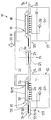
- the drawing schematically shows a treatment device 11 for plate-shaped objects 17, for example electrical circuit boards, ie insulating plastic plates which are usually provided on both sides with conductor tracks.
- the circuit boards shown quite thick in the schematic representation are in reality usually very thin, for example in the range of 25 ⁇ m or less. Accordingly, they are very flexible.
- the device 11 has two treatment stations which consist of elongated containers through which a transport device 15 runs along a horizontal transport plane 33. It also includes a turning station 14 provided between the two treatment stations.
- the transport device At its entrance and exit from each treatment station, the transport device has 12 lower belts 16 on which the object 17 is transported. These lower belts transfer the object to upper belts 18, which belong to a suction transport device 19.
- a suction box 20 is provided between the upper and lower run of the upper belts. It has suction openings 32 on its underside, through which the lower run of the possibly perforated upper band runs.
- the suction box is connected to a vacuum pump 22 via vacuum lines 21. Possibly. is still a liquid separator, not shown, e.g. a cyclone separator, interposed.
- the upper bands 18 extend over the entire length of the treatment area of each treatment station. Like the lower belts 16, they are driven.
- 33 spray nozzles 29 are arranged under the transport plane, which, viewed in the transport direction 34, are arranged in a row in several rows. They are supplied by a pump 28 with treatment medium which forms a sump in the container belonging to the treatment station.
- the treatment medium is a liquid, preferably for etching the coated printed circuit boards.
- other treatment media could be used.
- the advantages are particularly noticeable in treatments in which chemical or physical treatment takes place that is dependent on time and flushing intensity.
- spraying the liquid on it could also be brought to the object in other ways, for example in the form of gushing sections.
- a number of gushing sections could be connected in series in a treatment station 12, so that liquid can run off or drip off in between.
- the turning station 14 has synchronously driven upper and lower belts which, if necessary, only grasp the object at its edge. These belts, which clamp the object between them, can be pivoted about a turning axis 23. This could be perpendicular to the plane of the drawing, i.e. run horizontally and transversely to the transport direction 34. If it is desired to swap the top and bottom sides of the object 17 in the turning station, but also to turn them about a vertical axis, the turning axis 23 could, as indicated, be inclined, e.g. inclined at 45 ° to the plane of the drawing, but lying in the transport plane.
- the objects 17 run into the first treatment station 12 in the transport plane 33, which is formed at the inlet 25 by the upper side of the lower belts 16. Before the actual treatment area begins, they are removed from the Suction transport device 19 taken over, wherein rollers 35 arranged in front of and behind the upper belt support the transfer.
- the vacuum pump 22 continuously sucks air from the suction box 20 via the vacuum lines 21, which flows into the suction box 32.
- the perforated upper band 18 lies above the suction openings 32. However, it is also possible to provide the suction openings 32 parallel to non-perforated, relatively narrow upper bands.
- the treatment liquid is applied from below onto the object which is now suspended with a free underside. It can drip off immediately behind the nozzle, so that fresh treatment liquid is applied several times if there are several rows of nozzles arranged one after the other.
- the suction sections e.g. the number of holes and / or diameter of the perforations of the suction box at the location opposite each nozzle or row of nozzles are reduced or omitted entirely.
- Treatment liquid sucked into the suction box is separated from the suction air there and / or in the downstream liquid separator and returned to the circuit.
- the object runs into the turning station 14, which guides the object with its driven conveyor belts 24 and at the same time actively transports it.
- the turning station is rotated about the turning axis 23, so that the object with the previously treated side now ends up on the lower conveyor belt 16 of the second treatment station 13.
- the treatment cycle for the other side of the object 17 is carried out, also from below.
Landscapes
- Chemical & Material Sciences (AREA)
- Engineering & Computer Science (AREA)
- Materials Engineering (AREA)
- Chemical Kinetics & Catalysis (AREA)
- General Chemical & Material Sciences (AREA)
- Organic Chemistry (AREA)
- Manufacturing & Machinery (AREA)
- Geochemistry & Mineralogy (AREA)
- Life Sciences & Earth Sciences (AREA)
- Microelectronics & Electronic Packaging (AREA)
- Mechanical Engineering (AREA)
- Metallurgy (AREA)
- Manufacturing Of Printed Circuit Boards (AREA)
- Coating Apparatus (AREA)
- Non-Metallic Protective Coatings For Printed Circuits (AREA)
- Container, Conveyance, Adherence, Positioning, Of Wafer (AREA)
Applications Claiming Priority (2)
| Application Number | Priority Date | Filing Date | Title |
|---|---|---|---|
| DE19509313A DE19509313A1 (de) | 1995-03-15 | 1995-03-15 | Verfahren und Vorrichtung zum Behandeln von plattenförmigen Gegenständen, insbesondere Leiterplatten |
| DE19509313 | 1995-03-15 |
Publications (2)
| Publication Number | Publication Date |
|---|---|
| EP0732424A1 true EP0732424A1 (fr) | 1996-09-18 |
| EP0732424B1 EP0732424B1 (fr) | 1999-06-30 |
Family
ID=7756700
Family Applications (1)
| Application Number | Title | Priority Date | Filing Date |
|---|---|---|---|
| EP96103716A Expired - Lifetime EP0732424B1 (fr) | 1995-03-15 | 1996-03-09 | Méthode et dispositif pour le traitement de produits en forme de plaque, e.p. des circuits imprimés |
Country Status (3)
| Country | Link |
|---|---|
| EP (1) | EP0732424B1 (fr) |
| DE (2) | DE19509313A1 (fr) |
| ES (1) | ES2135807T3 (fr) |
Cited By (8)
| Publication number | Priority date | Publication date | Assignee | Title |
|---|---|---|---|---|
| US6174417B1 (en) | 1998-05-20 | 2001-01-16 | Process Automation International Ltd. | Electroplating machine |
| US6261425B1 (en) | 1998-08-28 | 2001-07-17 | Process Automation International, Ltd. | Electroplating machine |
| ITUD20090045A1 (it) * | 2009-02-23 | 2010-08-24 | Applied Materials Inc | Materiale di supporto substrato migliorato utile per procedimenti di stampa serigrafica |
| ITMO20110009A1 (it) * | 2011-01-21 | 2012-07-22 | Airone S R L | Impianto per la verniciatura pentole. |
| CN102916075A (zh) * | 2012-09-27 | 2013-02-06 | 奥特斯维能源(太仓)有限公司 | 一种制绒深度稳定的方法 |
| CN108097502A (zh) * | 2018-01-04 | 2018-06-01 | 海宁德阳高分子材料科技有限公司 | 一种高物性可压纹干法环保沙发革生产防腐装置 |
| CN110055577A (zh) * | 2019-05-07 | 2019-07-26 | 重庆平伟实业股份有限公司 | 一种轴向引线电子元器件的电镀装置和方法 |
| CN118207612A (zh) * | 2024-05-22 | 2024-06-18 | 深圳市晨翰科技有限公司 | 一种适用于手机保护膜的单面电镀设备 |
Families Citing this family (4)
| Publication number | Priority date | Publication date | Assignee | Title |
|---|---|---|---|---|
| DE19645760A1 (de) * | 1996-11-06 | 1998-05-07 | Schmid Gmbh & Co Geb | Verfahren und Vorrichtung zur Erzeugung eines definierten Stroms horizontal geführter Leiterplatten |
| DE19930207C2 (de) * | 1999-06-22 | 2001-12-06 | Schulz Harder Juergen | Verfahren zum Herstellen von Substraten mit strukturierten Metallisierungen sowie Halte- und Fixierelement zur Verwendung bei diesem Verfahren |
| EP1063873A3 (fr) | 1999-06-22 | 2003-04-23 | Dr.-Ing. Jürgen Schulz-Harder | Procédé de fabrication de substrats à métallisations structurées et élément de maintien et de fixation utilisé dans le procédé |
| DE10154884C5 (de) | 2001-11-05 | 2009-11-19 | Gebr. Schmid Gmbh & Co. | Vorrichtung zum Transport von flexiblem Flachmaterial, insbesondere Leiterplatten |
Citations (7)
| Publication number | Priority date | Publication date | Assignee | Title |
|---|---|---|---|---|
| DE2937388A1 (de) * | 1979-09-15 | 1981-04-16 | Hugo 6419 Eiterfeld Isert | Einrichtung zum behandeln von beschichteten platten |
| US4339297A (en) * | 1981-04-14 | 1982-07-13 | Seiichiro Aigo | Apparatus for etching of oxide film on semiconductor wafer |
| DE3602078A1 (de) * | 1986-01-24 | 1987-07-30 | Riba Prueftechnik Gmbh | Haltevorrichtung insbesondere fuer leiterplatten |
| EP0267874A1 (fr) * | 1986-11-10 | 1988-05-18 | Haas-Laser Systems AG | Procédé de transport d'objets plats perforés |
| EP0269566A1 (fr) * | 1986-11-10 | 1988-06-01 | Haas-Laser Systems AG | Dispositif de transport pour objets plats perforés |
| US4759817A (en) * | 1986-05-15 | 1988-07-26 | Seiichiro Aigo | Apparatus for etching semiconductor material |
| EP0498250A1 (fr) * | 1991-02-05 | 1992-08-12 | International Business Machines Corporation | Procédé de gravure régularisant la largeur des lignes de connexion |
-
1995
- 1995-03-15 DE DE19509313A patent/DE19509313A1/de not_active Withdrawn
-
1996
- 1996-03-09 EP EP96103716A patent/EP0732424B1/fr not_active Expired - Lifetime
- 1996-03-09 DE DE59602307T patent/DE59602307D1/de not_active Expired - Lifetime
- 1996-03-09 ES ES96103716T patent/ES2135807T3/es not_active Expired - Lifetime
Patent Citations (7)
| Publication number | Priority date | Publication date | Assignee | Title |
|---|---|---|---|---|
| DE2937388A1 (de) * | 1979-09-15 | 1981-04-16 | Hugo 6419 Eiterfeld Isert | Einrichtung zum behandeln von beschichteten platten |
| US4339297A (en) * | 1981-04-14 | 1982-07-13 | Seiichiro Aigo | Apparatus for etching of oxide film on semiconductor wafer |
| DE3602078A1 (de) * | 1986-01-24 | 1987-07-30 | Riba Prueftechnik Gmbh | Haltevorrichtung insbesondere fuer leiterplatten |
| US4759817A (en) * | 1986-05-15 | 1988-07-26 | Seiichiro Aigo | Apparatus for etching semiconductor material |
| EP0267874A1 (fr) * | 1986-11-10 | 1988-05-18 | Haas-Laser Systems AG | Procédé de transport d'objets plats perforés |
| EP0269566A1 (fr) * | 1986-11-10 | 1988-06-01 | Haas-Laser Systems AG | Dispositif de transport pour objets plats perforés |
| EP0498250A1 (fr) * | 1991-02-05 | 1992-08-12 | International Business Machines Corporation | Procédé de gravure régularisant la largeur des lignes de connexion |
Non-Patent Citations (2)
| Title |
|---|
| FIGULI E. S.: "Wafer plating fixture", WESTERN ELECTRIC TECHNICAL DIGEST, no. 30, 1 April 1973 (1973-04-01), pages 9 - 10, XP002007210 * |
| KELLER: "Ultrasonic fountain processor", IBM TECHNICAL DISCLOSURE BULLETIN, vol. 10, no. 5, 1 October 1967 (1967-10-01), NEW YORK US, pages 528 - 529, XP002007209 * |
Cited By (12)
| Publication number | Priority date | Publication date | Assignee | Title |
|---|---|---|---|---|
| US6174417B1 (en) | 1998-05-20 | 2001-01-16 | Process Automation International Ltd. | Electroplating machine |
| US6241860B1 (en) | 1998-05-20 | 2001-06-05 | Process Automation International, Ltd. | Electroplating machine |
| US6251234B1 (en) | 1998-05-20 | 2001-06-26 | Process Automation International, Ltd. | Electroplating machine |
| US6261425B1 (en) | 1998-08-28 | 2001-07-17 | Process Automation International, Ltd. | Electroplating machine |
| ITUD20090045A1 (it) * | 2009-02-23 | 2010-08-24 | Applied Materials Inc | Materiale di supporto substrato migliorato utile per procedimenti di stampa serigrafica |
| WO2010094347A1 (fr) * | 2009-02-23 | 2010-08-26 | Applied Materials, Inc. | Matériau de support de substrat amélioré utilisé dans des processus de sérigraphie |
| ITMO20110009A1 (it) * | 2011-01-21 | 2012-07-22 | Airone S R L | Impianto per la verniciatura pentole. |
| CN102916075A (zh) * | 2012-09-27 | 2013-02-06 | 奥特斯维能源(太仓)有限公司 | 一种制绒深度稳定的方法 |
| CN108097502A (zh) * | 2018-01-04 | 2018-06-01 | 海宁德阳高分子材料科技有限公司 | 一种高物性可压纹干法环保沙发革生产防腐装置 |
| CN110055577A (zh) * | 2019-05-07 | 2019-07-26 | 重庆平伟实业股份有限公司 | 一种轴向引线电子元器件的电镀装置和方法 |
| CN110055577B (zh) * | 2019-05-07 | 2021-03-12 | 重庆平伟实业股份有限公司 | 一种轴向引线电子元器件的电镀装置和方法 |
| CN118207612A (zh) * | 2024-05-22 | 2024-06-18 | 深圳市晨翰科技有限公司 | 一种适用于手机保护膜的单面电镀设备 |
Also Published As
| Publication number | Publication date |
|---|---|
| EP0732424B1 (fr) | 1999-06-30 |
| ES2135807T3 (es) | 1999-11-01 |
| DE19509313A1 (de) | 1996-09-19 |
| DE59602307D1 (de) | 1999-08-05 |
Similar Documents
| Publication | Publication Date | Title |
|---|---|---|
| EP0427053B1 (fr) | Dispositif et procédé de revêtement des cartes de circuits imprimés | |
| DE69729578T2 (de) | Flüssigkeitsabgabevorrichtung und -verfahren | |
| DE4107224C1 (fr) | ||
| DE69610763T2 (de) | Flüssigkeitenabgabevorrichtung und -verfahren | |
| DE4121032A1 (de) | Vorrichtung zum behandeln von plattenfoermigen gegenstaenden, insbesondere leiterplatten | |
| DE2320199B2 (de) | Verfahren und Vorrichtung zum Reinigen gedruckter Leiterplatten | |
| EP0732424A1 (fr) | Méthode et dispositif pour le traitement de produits en forme de plaque, e.p. des circuits imprimés | |
| WO2009077201A2 (fr) | Procédé et dispositif de traitement de tranches de silicium | |
| AT401133B (de) | Verfahren zum behandeln von stückförmigen teilen in durchlaufanlagen, sowie vorrichtung zur durchführung dieses verfahrens | |
| DE3721404C2 (fr) | ||
| DE69408490T2 (de) | Vorrichtung zur Behandlung von Gegenständen mit Flüssigkeiten | |
| EP1442646B1 (fr) | Dispositif pour transporter des produits plats flexibles, en particulier des cartes imprimees | |
| EP0970899B1 (fr) | Procédé et appareil pour traiter des objets en forme de tranches comme des tôles, vitres, circuits imprimés, substrats céramiques | |
| DE10039558A1 (de) | Vorrichtung zur Sprühbehandlung von Leiterplatten | |
| EP0399325A1 (fr) | Disposition pour le traitement et/ou le nettoyage de matériau, notamment des cartes de circuits imprimés pourvues de forures | |
| DE3817543A1 (de) | Maschine zum behandeln von gegenstaenden mit einer behandlungsfluessigkeit | |
| EP0441743A1 (fr) | Dispositif de transport pour plaques à surface sensible, en particulier pour circuits imprimÀ©s à recouvrement humide | |
| EP0752277A2 (fr) | Dispositif pour le traitement de produits flexibles en forme de plaque ou de feuille, e.p. des circuits imprimés | |
| DE20304601U1 (de) | Vorrichtung zum Transport von flexiblem Flachmaterial, insbesondere Leiterplatten | |
| EP2006029B1 (fr) | Dispositif d'application d'un produit d'application sur un substrat | |
| DE60300039T2 (de) | Vereinzelungsförderanlage | |
| DE4221994C2 (de) | Einrichtung zum Behandeln von fotografischen Schichtträgern | |
| DE102004040945B4 (de) | Verfahren und Vorrichtung zum selektiven Beschichten von Leiterplatten | |
| DE102007013637B4 (de) | Verfahren zum Beschichten von metallischen Werkstücken | |
| DE102015109635B4 (de) | Verfahren zum elektrischen Behandeln einer Folie sowie Vorrichtung hierzu |
Legal Events
| Date | Code | Title | Description |
|---|---|---|---|
| PUAI | Public reference made under article 153(3) epc to a published international application that has entered the european phase |
Free format text: ORIGINAL CODE: 0009012 |
|
| AK | Designated contracting states |
Kind code of ref document: A1 Designated state(s): DE ES FR GB IT SE |
|
| 17P | Request for examination filed |
Effective date: 19960925 |
|
| 17Q | First examination report despatched |
Effective date: 19970613 |
|
| GRAG | Despatch of communication of intention to grant |
Free format text: ORIGINAL CODE: EPIDOS AGRA |
|
| GRAG | Despatch of communication of intention to grant |
Free format text: ORIGINAL CODE: EPIDOS AGRA |
|
| GRAH | Despatch of communication of intention to grant a patent |
Free format text: ORIGINAL CODE: EPIDOS IGRA |
|
| GRAH | Despatch of communication of intention to grant a patent |
Free format text: ORIGINAL CODE: EPIDOS IGRA |
|
| GRAA | (expected) grant |
Free format text: ORIGINAL CODE: 0009210 |
|
| AK | Designated contracting states |
Kind code of ref document: B1 Designated state(s): DE ES FR GB IT SE |
|
| ET | Fr: translation filed | ||
| GBT | Gb: translation of ep patent filed (gb section 77(6)(a)/1977) |
Effective date: 19990714 |
|
| REF | Corresponds to: |
Ref document number: 59602307 Country of ref document: DE Date of ref document: 19990805 |
|
| ITF | It: translation for a ep patent filed | ||
| REG | Reference to a national code |
Ref country code: ES Ref legal event code: FG2A Ref document number: 2135807 Country of ref document: ES Kind code of ref document: T3 |
|
| PLBE | No opposition filed within time limit |
Free format text: ORIGINAL CODE: 0009261 |
|
| STAA | Information on the status of an ep patent application or granted ep patent |
Free format text: STATUS: NO OPPOSITION FILED WITHIN TIME LIMIT |
|
| 26N | No opposition filed | ||
| REG | Reference to a national code |
Ref country code: GB Ref legal event code: IF02 |
|
| PGFP | Annual fee paid to national office [announced via postgrant information from national office to epo] |
Ref country code: GB Payment date: 20030224 Year of fee payment: 8 |
|
| PGFP | Annual fee paid to national office [announced via postgrant information from national office to epo] |
Ref country code: FR Payment date: 20030318 Year of fee payment: 8 |
|
| PGFP | Annual fee paid to national office [announced via postgrant information from national office to epo] |
Ref country code: SE Payment date: 20030324 Year of fee payment: 8 |
|
| PG25 | Lapsed in a contracting state [announced via postgrant information from national office to epo] |
Ref country code: GB Free format text: LAPSE BECAUSE OF NON-PAYMENT OF DUE FEES Effective date: 20040309 |
|
| PG25 | Lapsed in a contracting state [announced via postgrant information from national office to epo] |
Ref country code: SE Free format text: LAPSE BECAUSE OF NON-PAYMENT OF DUE FEES Effective date: 20040310 |
|
| GBPC | Gb: european patent ceased through non-payment of renewal fee | ||
| EUG | Se: european patent has lapsed | ||
| PG25 | Lapsed in a contracting state [announced via postgrant information from national office to epo] |
Ref country code: FR Free format text: LAPSE BECAUSE OF NON-PAYMENT OF DUE FEES Effective date: 20041130 |
|
| REG | Reference to a national code |
Ref country code: FR Ref legal event code: ST |
|
| PGFP | Annual fee paid to national office [announced via postgrant information from national office to epo] |
Ref country code: ES Payment date: 20060320 Year of fee payment: 11 |
|
| PGFP | Annual fee paid to national office [announced via postgrant information from national office to epo] |
Ref country code: IT Payment date: 20060331 Year of fee payment: 11 |
|
| REG | Reference to a national code |
Ref country code: ES Ref legal event code: FD2A Effective date: 20070310 |
|
| PG25 | Lapsed in a contracting state [announced via postgrant information from national office to epo] |
Ref country code: ES Free format text: LAPSE BECAUSE OF NON-PAYMENT OF DUE FEES Effective date: 20070310 |
|
| PG25 | Lapsed in a contracting state [announced via postgrant information from national office to epo] |
Ref country code: IT Free format text: LAPSE BECAUSE OF NON-PAYMENT OF DUE FEES Effective date: 20070309 |
|
| PGFP | Annual fee paid to national office [announced via postgrant information from national office to epo] |
Ref country code: DE Payment date: 20110322 Year of fee payment: 16 |
|
| REG | Reference to a national code |
Ref country code: DE Ref legal event code: R119 Ref document number: 59602307 Country of ref document: DE Effective date: 20121002 |
|
| PG25 | Lapsed in a contracting state [announced via postgrant information from national office to epo] |
Ref country code: DE Free format text: LAPSE BECAUSE OF NON-PAYMENT OF DUE FEES Effective date: 20121002 |